1999 SUBARU LEGACY length
[x] Cancel search: lengthPage 995 of 1456
8. Leak Testing
A: INSPECTION
The following points should be kept in mind when
conducting a refrigerant leak test.
1) The A/C system to be tested must have an
adequate refrigerant charge to begin with.
2) The area where the leak test is conducted must
be free of wind and drafts, with still air being the
ideal condition.
3) The atmosphere where the leak test is con-
ducted must be free of refrigerant contamination.
4) Operate the A/C system for approx. 10 minutes,
then turn the engine off an begin the leak test.
5) Refrigerant gas is heavier than air, therefore
always hold the probe below the connection being
tested.
6) When checking for a leak along a length of
hose or tube, the leak detector probe must be
moved slowly, approx. 25 mm (1 in) per second
making sure probe does not come in contact with
the component being tested.
7) When checking for a leak at a certain point, the
leak detector probe must be held at that point for
at least 5 seconds.
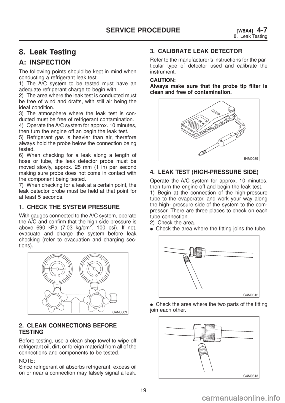
1. CHECK THE SYSTEM PRESSURE
With gauges connected to the A/C system, operate
the A/C and confirm that the high side pressure is
above 690 kPa (7.03 kg/cm
2, 100 psi). If not,
evacuate and charge the system before leak
checking (refer to evacuation and charging sec-
tions).
G4M0609
2. CLEAN CONNECTIONS BEFORE
TESTING
Before testing, use a clean shop towel to wipe off
refrigerant oil, dirt, or foreign material from all of the
connections and components to be tested.
NOTE:
Since refrigerant oil absorbs refrigerant, excess oil
on or near a connection may falsely signal a leak.
3. CALIBRATE LEAK DETECTOR
Refer to the manufacturer's instructions for the par-
ticular type of detector used and calibrate the
instrument.
CAUTION:
Always make sure that the probe tip filter is
clean and free of contamination.
B4M0089
4. LEAK TEST (HIGH-PRESSURE SIDE)
Operate the A/C system for approx. 10 minutes,
then turn the engine off and begin the leak test.
1) Begin at the connection of the high-pressure
tube to the evaporator, and work your way along
the high- pressure side of the system to the com-
pressor. There are three places to check on each
tube connection.
2) Check the area.
ICheck the area where the fitting joins the tube.
G4M0612
ICheck the area where the two parts of the fitting
join each other.
G4M0613
19
[W8A4]4-7SERVICE PROCEDURE
8. Leak Testing
Page 996 of 1456
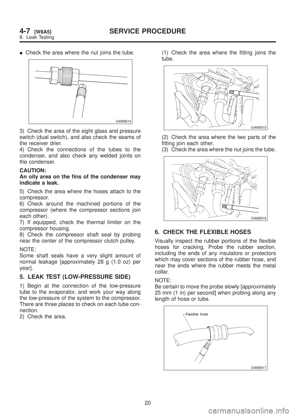
ICheck the area where the nut joins the tube.
G4M0614
3) Check the area of the sight glass and pressure
switch (dual switch), and also check the seams of
the receiver drier.
4) Check the connections of the tubes to the
condenser, and also check any welded joints on
the condenser.
CAUTION:
An oily area on the fins of the condenser may
indicate a leak.
5) Check the area where the hoses attach to the
compressor.
6) Check around the machined portions of the
compressor (where the compressor sections join
each other).
7) If equipped, check the thermal limiter on the
compressor housing.
8) Check the compressor shaft seal by probing
near the center of the compressor clutch pulley.
NOTE:
Some shaft seals have a very slight amount of
normal leakage [approximately 28 g (1.0 oz) per
year].
5. LEAK TEST (LOW-PRESSURE SIDE)
1) Begin at the connection of the low-pressure
tube to the evaporator, and work your way along
the low-pressure of the system to the compressor.
There are three places to check on each tube con-
nection.
2) Check the area.(1) Check the area where the fitting joins the
tube.
G4M0615
(2) Check the area where the two parts of the
fitting join each other.
(3) Check the area where the nut joins the tube.
G4M0616
6. CHECK THE FLEXIBLE HOSES
Visually inspect the rubber portions of the flexible
hoses for cracking. Probe the rubber section,
including the ends of any insulators or protectors
which may cover sections of the rubber hose, and
near the ends where the rubber meets the metal
collar.
NOTE:
Be certain to move the probe slowly [approximately
25 mm (1 in) per second] when probing along any
length of hose or tube.
G4M0617
20
4-7[W8A5]SERVICE PROCEDURE
8. Leak Testing
Page 1061 of 1456
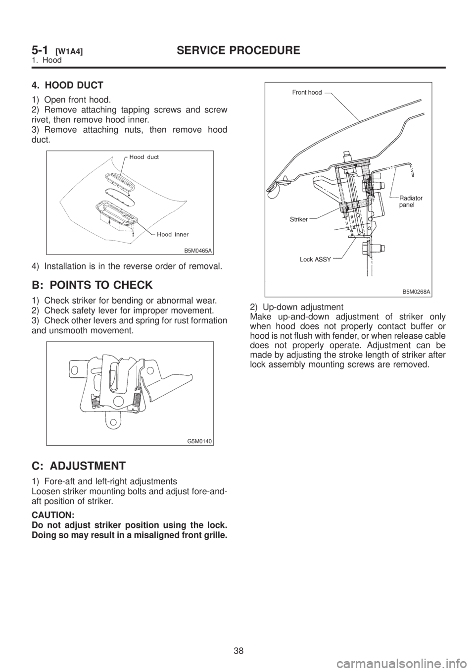
4. HOOD DUCT
1) Open front hood.
2) Remove attaching tapping screws and screw
rivet, then remove hood inner.
3) Remove attaching nuts, then remove hood
duct.
B5M0465A
4) Installation is in the reverse order of removal.
B: POINTS TO CHECK
1) Check striker for bending or abnormal wear.
2) Check safety lever for improper movement.
3) Check other levers and spring for rust formation
and unsmooth movement.
G5M0140
C: ADJUSTMENT
1) Fore-aft and left-right adjustments
Loosen striker mounting bolts and adjust fore-and-
aft position of striker.
CAUTION:
Do not adjust striker position using the lock.
Doing so may result in a misaligned front grille.
B5M0268A
2) Up-down adjustment
Make up-and-down adjustment of striker only
when hood does not properly contact buffer or
hood is not flush with fender, or when release cable
does not properly operate. Adjustment can be
made by adjusting the stroke length of striker after
lock assembly mounting screws are removed.
38
5-1[W1A4]SERVICE PROCEDURE
1. Hood
Page 1073 of 1456
Process
No.Process name Job contents
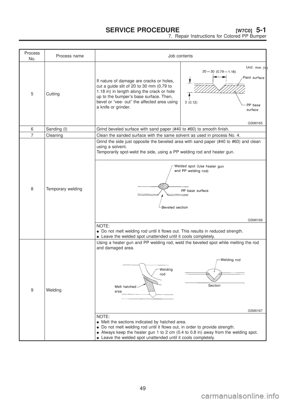
5 CuttingIf nature of damage are cracks or holes,
cut a guide slit of 20 to 30 mm (0.79 to
1.18 in) in length along the crack or hole
up to the bumper's base surface. Then,
bevel or ªvee- outº the affected area using
a knife or grinder.
G5M0165
6 Sanding (I) Grind beveled surface with sand paper (#40 to #60) to smooth finish.
7 Cleaning Clean the sanded surface with the same solvent as used in process No. 4.
8 Temporary weldingGrind the side just opposite the beveled area with sand paper (#40 to #60) and clean
using a solvent.
Temporarily spot-weld the side, using a PP welding rod and heater gun.
G5M0166
NOTE:
IDo not melt welding rod until it flows out. This results in reduced strength.
ILeave the welded spot unattended until it cools completely.
9 WeldingUsing a heater gun and PP welding rod, weld the beveled spot while melting the rod
and damaged area.
G5M0167
NOTE:
IMelt the sections indicated by hatched area.
IDo not melt welding rod until it flows out, in order to provide strength.
IAlways keep the heater gun 1 to 2 cm (0.4 to 0.8 in) away from the welding spot.
ILeave the welded spot unattended until it cools completely.
49
[W7C0]5-1SERVICE PROCEDURE
7. Repair Instructions for Colored PP Bumper
Page 1086 of 1456
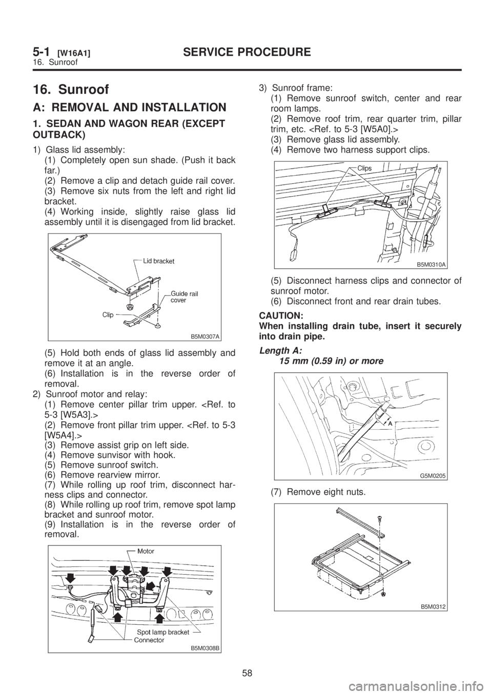
16. Sunroof
A: REMOVAL AND INSTALLATION
1. SEDAN AND WAGON REAR (EXCEPT
OUTBACK)
1) Glass lid assembly:
(1) Completely open sun shade. (Push it back
far.)
(2) Remove a clip and detach guide rail cover.
(3) Remove six nuts from the left and right lid
bracket.
(4) Working inside, slightly raise glass lid
assembly until it is disengaged from lid bracket.
B5M0307A
(5) Hold both ends of glass lid assembly and
remove it at an angle.
(6) Installation is in the reverse order of
removal.
2) Sunroof motor and relay:
(1) Remove center pillar trim upper.
(2) Remove front pillar trim upper.
(3) Remove assist grip on left side.
(4) Remove sunvisor with hook.
(5) Remove sunroof switch.
(6) Remove rearview mirror.
(7) While rolling up roof trim, disconnect har-
ness clips and connector.
(8) While rolling up roof trim, remove spot lamp
bracket and sunroof motor.
(9) Installation is in the reverse order of
removal.
B5M0308B
3) Sunroof frame:
(1) Remove sunroof switch, center and rear
room lamps.
(2) Remove roof trim, rear quarter trim, pillar
trim, etc.
(3) Remove glass lid assembly.
(4) Remove two harness support clips.
B5M0310A
(5) Disconnect harness clips and connector of
sunroof motor.
(6) Disconnect front and rear drain tubes.
CAUTION:
When installing drain tube, insert it securely
into drain pipe.
Length A:
15 mm (0.59 in) or more
G5M0205
(7) Remove eight nuts.
B5M0312
58
5-1[W16A1]SERVICE PROCEDURE
16. Sunroof
Page 1097 of 1456
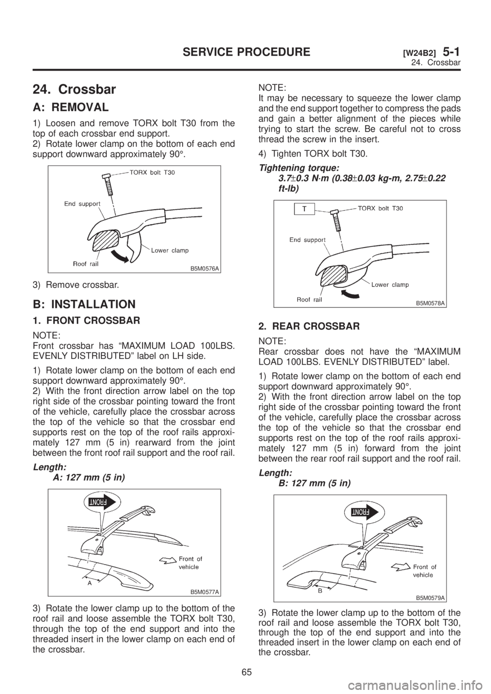
24. Crossbar
A: REMOVAL
1) Loosen and remove TORX bolt T30 from the
top of each crossbar end support.
2) Rotate lower clamp on the bottom of each end
support downward approximately 90É.
B5M0576A
3) Remove crossbar.
B: INSTALLATION
1. FRONT CROSSBAR
NOTE:
Front crossbar has ªMAXIMUM LOAD 100LBS.
EVENLY DISTRIBUTEDº label on LH side.
1) Rotate lower clamp on the bottom of each end
support downward approximately 90É.
2) With the front direction arrow label on the top
right side of the crossbar pointing toward the front
of the vehicle, carefully place the crossbar across
the top of the vehicle so that the crossbar end
supports rest on the top of the roof rails approxi-
mately 127 mm (5 in) rearward from the joint
between the front roof rail support and the roof rail.
Length:
A: 127 mm (5 in)
B5M0577A
3) Rotate the lower clamp up to the bottom of the
roof rail and loose assemble the TORX bolt T30,
through the top of the end support and into the
threaded insert in the lower clamp on each end of
the crossbar.NOTE:
It may be necessary to squeeze the lower clamp
and the end support together to compress the pads
and gain a better alignment of the pieces while
trying to start the screw. Be careful not to cross
thread the screw in the insert.
4) Tighten TORX bolt T30.
Tightening torque:
3.7
±0.3 N´m (0.38±0.03 kg-m, 2.75±0.22
ft-lb)
B5M0578A
2. REAR CROSSBAR
NOTE:
Rear crossbar does not have the ªMAXIMUM
LOAD 100LBS. EVENLY DISTRIBUTEDº label.
1) Rotate lower clamp on the bottom of each end
support downward approximately 90É.
2) With the front direction arrow label on the top
right side of the crossbar pointing toward the front
of the vehicle, carefully place the crossbar across
the top of the vehicle so that the crossbar end
supports rest on the top of the roof rails approxi-
mately 127 mm (5 in) forward from the joint
between the rear roof rail support and the roof rail.
Length:
B: 127 mm (5 in)
B5M0579A
3) Rotate the lower clamp up to the bottom of the
roof rail and loose assemble the TORX bolt T30,
through the top of the end support and into the
threaded insert in the lower clamp on each end of
the crossbar.
65
[W24B2]5-1SERVICE PROCEDURE
24. Crossbar
Page 1127 of 1456
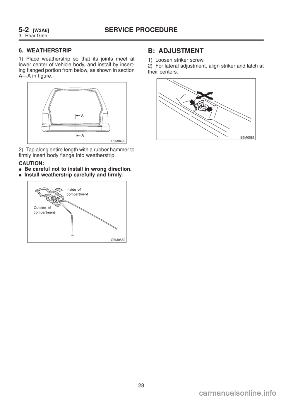
6. WEATHERSTRIP
1) Place weatherstrip so that its joints meet at
lower center of vehicle body, and install by insert-
ing flanged portion from below, as shown in section
AÐA in figure.
G5M0492
2) Tap along entire length with a rubber hammer to
firmly insert body flange into weatherstrip.
CAUTION:
IBe careful not to install in wrong direction.
IInstall weatherstrip carefully and firmly.
G5M0552
B: ADJUSTMENT
1) Loosen striker screw.
2) For lateral adjustment, align striker and latch at
their centers.
B5M0086
28
5-2[W3A6]SERVICE PROCEDURE
3. Rear Gate
Page 1194 of 1456
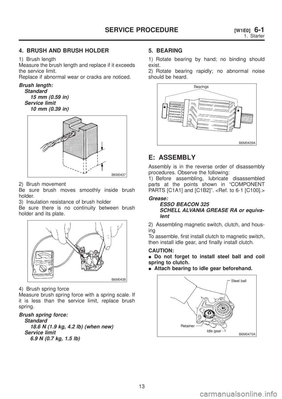
4. BRUSH AND BRUSH HOLDER
1) Brush length
Measure the brush length and replace if it exceeds
the service limit.
Replace if abnormal wear or cracks are noticed.
Brush length:
Standard
15 mm (0.59 in)
Service limit
10 mm (0.39 in)
B6M0437
2) Brush movement
Be sure brush moves smoothly inside brush
holder.
3) Insulation resistance of brush holder
Be sure there is no continuity between brush
holder and its plate.
B6M0438
4) Brush spring force
Measure brush spring force with a spring scale. If
it is less than the service limit, replace brush
spring.
Brush spring force:
Standard
18.6 N (1.9 kg, 4.2 lb) (when new)
Service limit
6.9 N (0.7 kg, 1.5 lb)
5. BEARING
1) Rotate bearing by hand; no binding should
exist.
2) Rotate bearing rapidly; no abnormal noise
should be heard.
B6M0439A
E: ASSEMBLY
Assembly is in the reverse order of disassembly
procedures. Observe the following:
1) Before assembling, lubricate disassembled
parts at the points shown in ªCOMPONENT
PARTS [C1A1] and [C1B2]º.
Grease:
ESSO BEACON 325
SCHELL ALVANIA GREASE RA or equiva-
lent
2) Assembling magnetic switch, clutch, and hous-
ing
To assemble, first install clutch to magnetic switch,
then install idle gear, and finally install clutch.
CAUTION:
IDo not forget to install steel ball and coil
spring to clutch.
IAttach bearing to idle gear beforehand.
B6M0470A
13
[W1E0]6-1SERVICE PROCEDURE
1. Starter