Page 874 of 1456
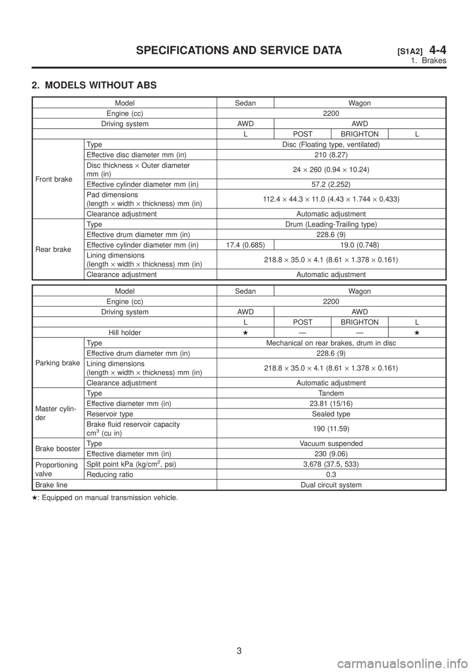
2. MODELS WITHOUT ABS
Model Sedan Wagon
Engine (cc) 2200
Driving system AWD AWD
L POST BRIGHTON L
Front brakeType Disc (Floating type, ventilated)
Effective disc diameter mm (in) 210 (8.27)
Disc thickness´Outer diameter
mm (in)24´260 (0.94´10.24)
Effective cylinder diameter mm (in) 57.2 (2.252)
Pad dimensions
(length´width´thickness) mm (in)112.4´44.3´11.0 (4.43´1.744´0.433)
Clearance adjustment Automatic adjustment
Rear brakeType Drum (Leading-Trailing type)
Effective drum diameter mm (in) 228.6 (9)
Effective cylinder diameter mm (in) 17.4 (0.685) 19.0 (0.748)
Lining dimensions
(length´width´thickness) mm (in)218.8´35.0´4.1 (8.61´1.378´0.161)
Clearance adjustment Automatic adjustment
Model Sedan Wagon
Engine (cc) 2200
Driving system AWD AWD
L POST BRIGHTON L
Hill holderHÐÐH
Parking brakeType Mechanical on rear brakes, drum in disc
Effective drum diameter mm (in) 228.6 (9)
Lining dimensions
(length´width´thickness) mm (in)218.8´35.0´4.1 (8.61´1.378´0.161)
Clearance adjustment Automatic adjustment
Master cylin-
derType Tandem
Effective diameter mm (in) 23.81 (15/16)
Reservoir type Sealed type
Brake fluid reservoir capacity
cm
3(cu in)190 (11.59)
Brake boosterType Vacuum suspended
Effective diameter mm (in) 230 (9.06)
Proportioning
valveSplit point kPa (kg/cm
2, psi) 3,678 (37.5, 533)
Reducing ratio 0.3
Brake lineDual circuit system
H: Equipped on manual transmission vehicle.
3
[S1A2]4-4SPECIFICATIONS AND SERVICE DATA
1. Brakes
Page 875 of 1456
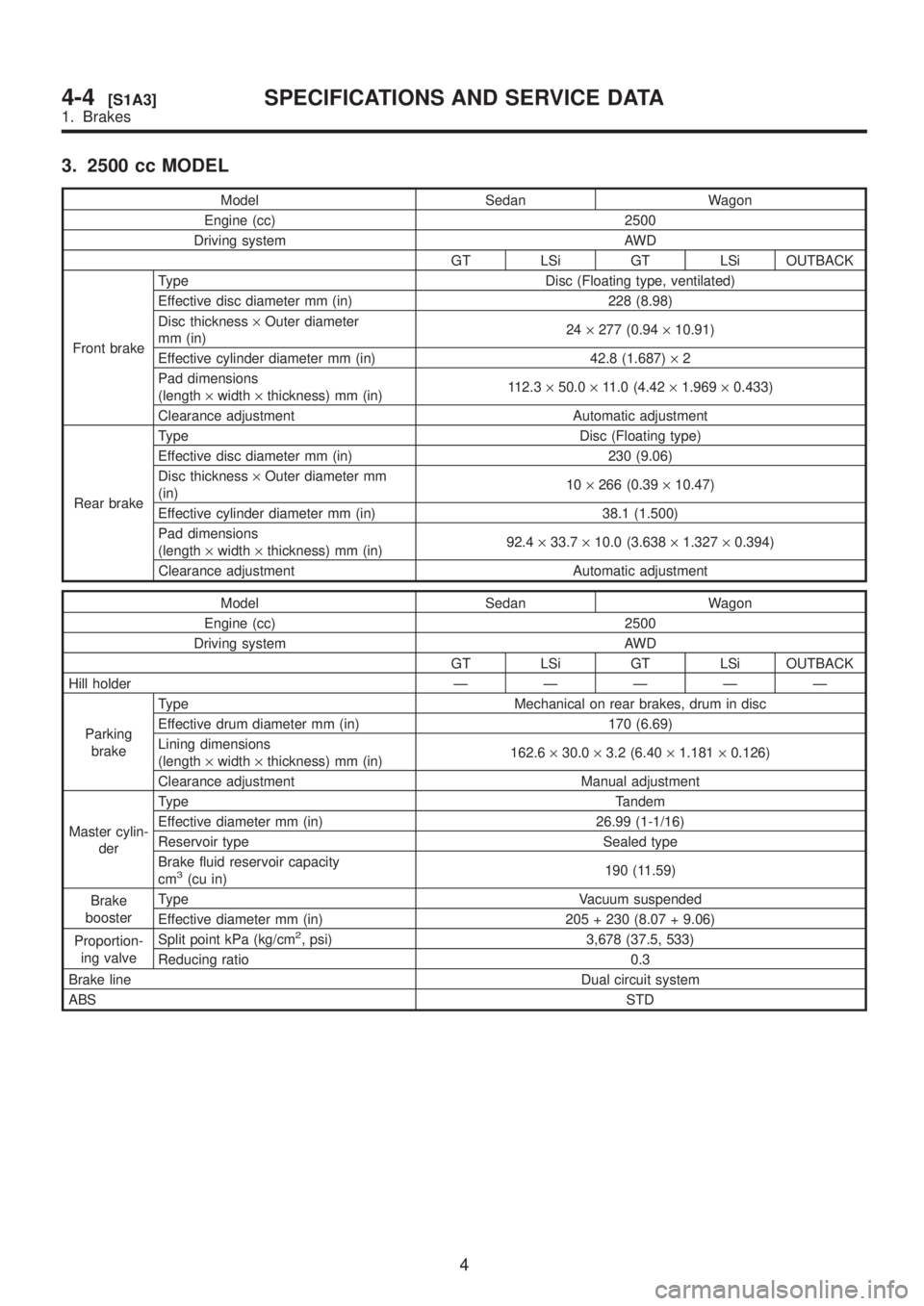
3. 2500 cc MODEL
Model Sedan Wagon
Engine (cc) 2500
Driving system AWD
GT LSi GT LSi OUTBACK
Front brakeType Disc (Floating type, ventilated)
Effective disc diameter mm (in) 228 (8.98)
Disc thickness´Outer diameter
mm (in)24´277 (0.94´10.91)
Effective cylinder diameter mm (in) 42.8 (1.687)´2
Pad dimensions
(length´width´thickness) mm (in)112.3´50.0´11.0 (4.42´1.969´0.433)
Clearance adjustment Automatic adjustment
Rear brakeType Disc (Floating type)
Effective disc diameter mm (in) 230 (9.06)
Disc thickness´Outer diameter mm
(in)10´266 (0.39´10.47)
Effective cylinder diameter mm (in) 38.1 (1.500)
Pad dimensions
(length´width´thickness) mm (in)92.4´33.7´10.0 (3.638´1.327´0.394)
Clearance adjustment Automatic adjustment
Model Sedan Wagon
Engine (cc) 2500
Driving system AWD
GT LSi GT LSi OUTBACK
Hill holderÐÐÐÐÐ
Parking
brakeType Mechanical on rear brakes, drum in disc
Effective drum diameter mm (in) 170 (6.69)
Lining dimensions
(length´width´thickness) mm (in)162.6´30.0´3.2 (6.40´1.181´0.126)
Clearance adjustment Manual adjustment
Master cylin-
derType Tandem
Effective diameter mm (in) 26.99 (1-1/16)
Reservoir type Sealed type
Brake fluid reservoir capacity
cm
3(cu in)190 (11.59)
Brake
boosterType Vacuum suspended
Effective diameter mm (in) 205 + 230 (8.07 + 9.06)
Proportion-
ing valveSplit point kPa (kg/cm
2, psi) 3,678 (37.5, 533)
Reducing ratio 0.3
Brake lineDual circuit system
ABSSTD
4
4-4[S1A3]SPECIFICATIONS AND SERVICE DATA
1. Brakes
Page 913 of 1456
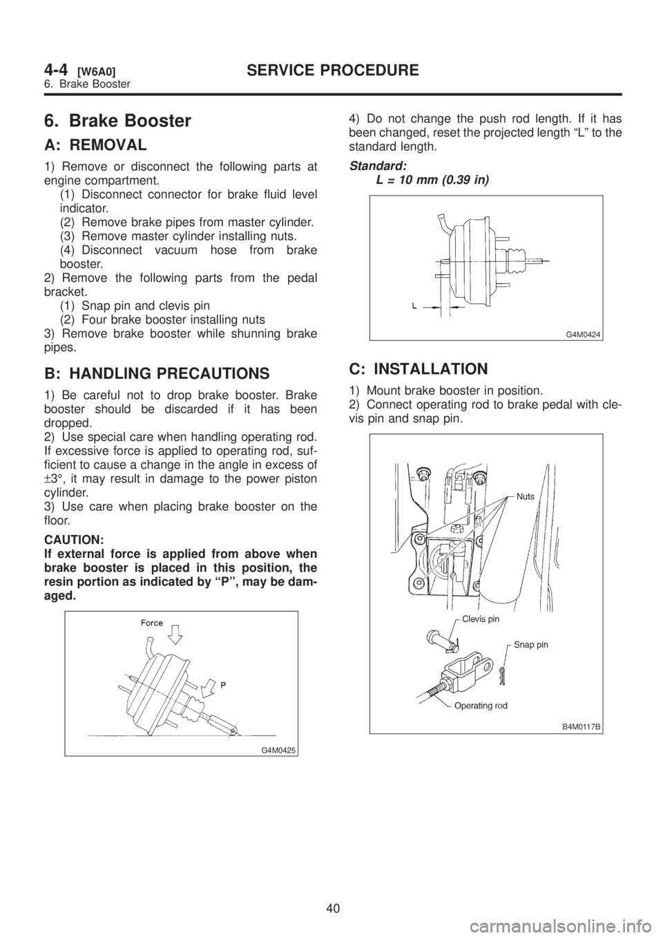
6. Brake Booster
A: REMOVAL
1) Remove or disconnect the following parts at
engine compartment.
(1) Disconnect connector for brake fluid level
indicator.
(2) Remove brake pipes from master cylinder.
(3) Remove master cylinder installing nuts.
(4) Disconnect vacuum hose from brake
booster.
2) Remove the following parts from the pedal
bracket.
(1) Snap pin and clevis pin
(2) Four brake booster installing nuts
3) Remove brake booster while shunning brake
pipes.
B: HANDLING PRECAUTIONS
1) Be careful not to drop brake booster. Brake
booster should be discarded if it has been
dropped.
2) Use special care when handling operating rod.
If excessive force is applied to operating rod, suf-
ficient to cause a change in the angle in excess of
±3É, it may result in damage to the power piston
cylinder.
3) Use care when placing brake booster on the
floor.
CAUTION:
If external force is applied from above when
brake booster is placed in this position, the
resin portion as indicated by ªPº, may be dam-
aged.
G4M0425
4) Do not change the push rod length. If it has
been changed, reset the projected length ªLº to the
standard length.
Standard:
L = 10 mm (0.39 in)
G4M0424
C: INSTALLATION
1) Mount brake booster in position.
2) Connect operating rod to brake pedal with cle-
vis pin and snap pin.
B4M0117B
40
4-4[W6A0]SERVICE PROCEDURE
6. Brake Booster
Page 951 of 1456
1. Pedal
A: ON-CAR SERVICE
1. BRAKE PEDAL
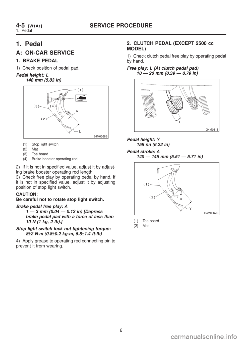
1) Check position of pedal pad.
Pedal height: L
148 mm (5.83 in)
B4M0366B
(1) Stop light switch
(2) Mat
(3) Toe board
(4) Brake booster operating rod
2) If it is not in specified value, adjust it by adjust-
ing brake booster operating rod length.
3) Check free play by operating pedal by hand. If
it is not in specified value, adjust it by adjusting
position of stop light switch.
CAUTION:
Be careful not to rotate stop light switch.
Brake pedal free play: A
1Ð3mm(0.04 Ð 0.12 in) [Depress
brake pedal pad with a force of less than
10 N (1 kg, 2 lb).]
Stop light switch lock nut tightening torque:
8
±2 N´m (0.8±0.2 kg-m, 5.8±1.4 ft-lb)
4) Apply grease to operating rod connecting pin to
prevent it from wearing.
2. CLUTCH PEDAL (EXCEPT 2500 cc
MODEL)
1) Check clutch pedal free play by operating pedal
by hand.
Free play: L (At clutch pedal pad)
10 Ð 20 mm (0.39 Ð 0.79 in)
G4M0318
Pedal height: Y
158 nn (6.22 in)
Pedal stroke: A
140 Ð 145 mm (5.51 Ð 5.71 in)
B4M0367B
(1) Toe board
(2) Mat
6
4-5[W1A1]SERVICE PROCEDURE
1. Pedal
Page 956 of 1456
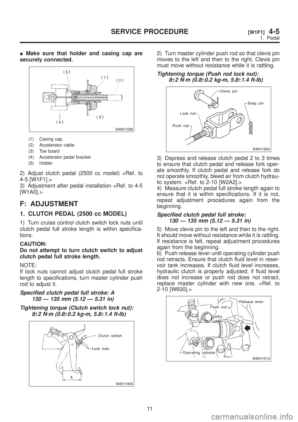
IMake sure that holder and casing cap are
securely connected.
B4M0159B
(1) Casing cap
(2) Accelerator cable
(3) Toe board
(4) Accelerator pedal bracket
(5) Holder
2) Adjust clutch pedal (2500 cc model)
4-5 [W1F1].>
3) Adjustment after pedal installation
[W1A0].>
F: ADJUSTMENT
1. CLUTCH PEDAL (2500 cc MODEL)
1) Turn cruise control clutch switch lock nuts until
clutch pedal full stroke length is within specifica-
tions.
CAUTION:
Do not attempt to turn clutch switch to adjust
clutch pedal full stroke length.
NOTE:
If lock nuts cannot adjust clutch pedal full stroke
length to specifications, turn master cylinder push
rod to adjust it.
Specified clutch pedal full stroke: A
130 Ð 135 mm (5.12 Ð 5.31 in)
Tightening torque (Clutch switch lock nut):
8
±2 N´m (0.8±0.2 kg-m, 5.8±1.4 ft-lb)
B4M1190A
2) Turn master cylinder push rod so that clevis pin
moves to the left and then to the right. Clevis pin
must move without resistance while it is rattling.
Tightening torque (Push rod lock nut):
8
±2 N´m (0.8±0.2 kg-m, 5.8±1.4 ft-lb)
B4M1189A
3) Depress and release clutch pedal 2 to 3 times
to ensure that clutch pedal and release fork oper-
ate smoothly. If clutch pedal and release fork do
not operate smoothly, bleed air from clutch hydrau-
lic system.
4) Measure clutch pedal full stroke length again to
ensure that it is within specifications. If it is not,
repeat adjustment procedures again from the
beginning.
Specified clutch pedal full stroke:
130 Ð 135 mm (5.12 Ð 5.31 in)
5) Move clevis pin to the left and then to the right.
It should move without resistance while it is rattling.
If resistance is felt, repeat adjustment procedures
again from the beginning.
6) Push release lever until operating cylinder push
rod retracts. Ensure that clutch fluid level in reser-
voir tank increases. If clutch fluid level increases,
hydraulic clutch is properly adjusted; if fluid level
does not increase or push rod does not retract,
replace master cylinder with new one.
2-10 [W600].>
B4M1191A
11
[W1F1]4-5SERVICE PROCEDURE
1. Pedal
Page 962 of 1456
1. Specifications
A: HEATER SYSTEM
Item Specifications Condition
Heating capacity 4.652 kW (4,000 kcal/h, 15,872 BTU/h) or more ...
When 300 m
3(10,593 cu ft)/hMode selector switch HEAT
Temp. control lever FULL HOT
Temperature difference
between hot water and
inlet air65ÉC (149ÉF)
Hot water flow rate 360(95.1 US
gal, 79.2 Imp
gal)/h
Air flow rate 300 m
3(10,593 cu ft)/h Heat mode (FRESH), FULL HOT at 12.5
V
Max air flow rate 510 m
3(18,008 cu ft)/h Temperature control
leverFULL COLD
Blower fan speed 4th position
RECIRC switch position RECIRC
Heater core size (height´
length´width´thickness)193.5´152.0´25.0´0.9 mm
(7.62´5.98´0.984´0.035 in)Ð
Blower
motorType Magnet motor 230 W or less at 12 V
Fan type and
size
(diameter´
width)Sirocco fan type
150´75 mm (5.91´2.95 in)
Ð
2
4-6[S1A0]SPECIFICATIONS AND SERVICE DATA
1. Specifications
Page 967 of 1456
1. Precaution
A: SUPPLEMENTAL RESTRAINT
SYSTEM ªAIRBAGº
CAUTION:
IAll Airbag system wiring harness and con-
nectors are colored yellow. Do not use electri-
cal test equipment on these circuit.
IBe careful not to damage Airbag system wir-
ing harness when servicing the instrument
panel, heater unit, blower motor and control
unit.
Airbag system wiring harness is routed near the
instrument panel, heater unit, blower motor and
control unit.
2. Heater Unit
A: REMOVAL AND INSTALLATION
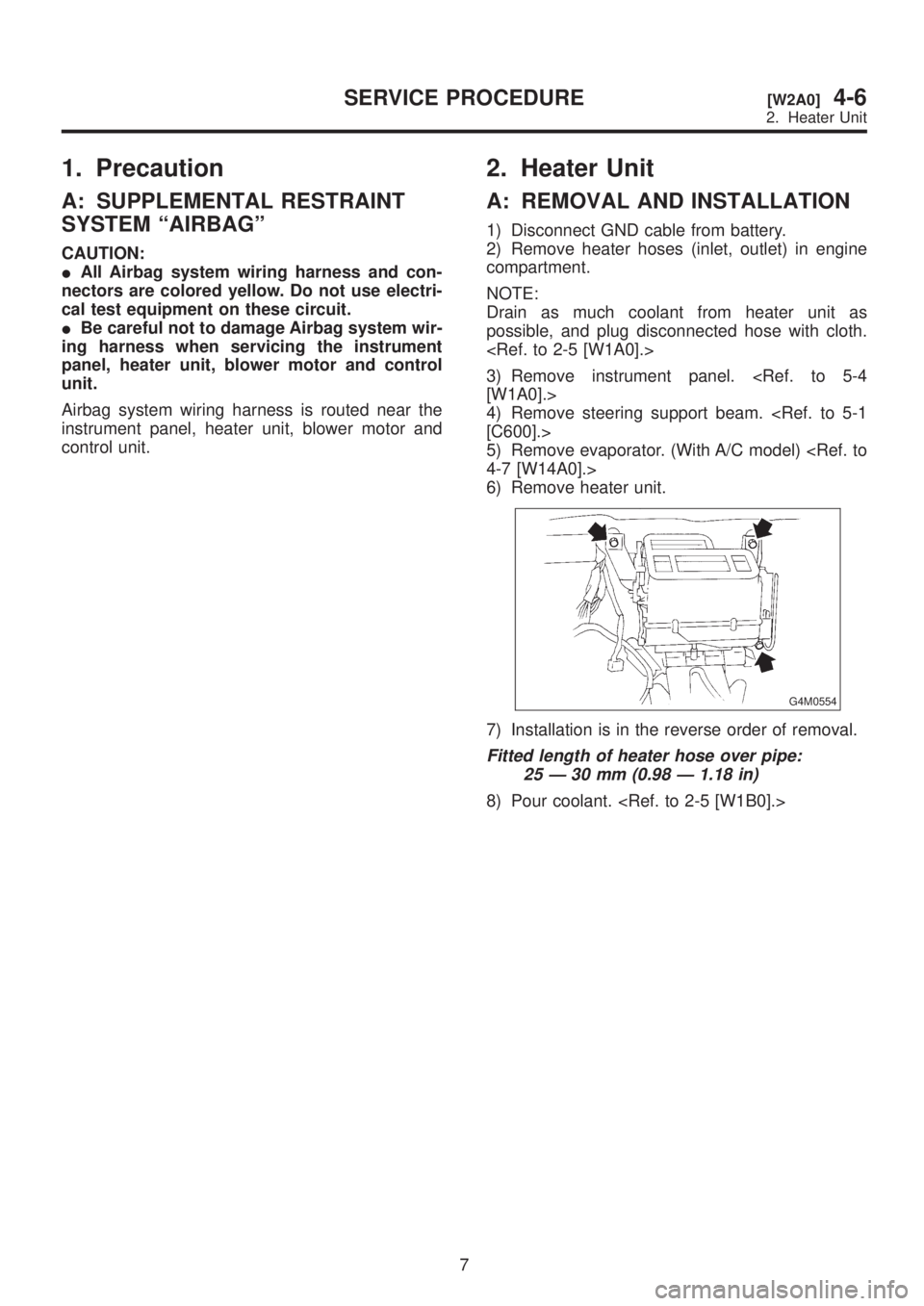
1) Disconnect GND cable from battery.
2) Remove heater hoses (inlet, outlet) in engine
compartment.
NOTE:
Drain as much coolant from heater unit as
possible, and plug disconnected hose with cloth.
3) Remove instrument panel.
[W1A0].>
4) Remove steering support beam.
[C600].>
5) Remove evaporator. (With A/C model)
4-7 [W14A0].>
6) Remove heater unit.
G4M0554
7) Installation is in the reverse order of removal.
Fitted length of heater hose over pipe:
25 Ð 30 mm (0.98 Ð 1.18 in)
8) Pour coolant.
7
[W2A0]4-6SERVICE PROCEDURE
2. Heater Unit
Page 968 of 1456
1. Precaution
A: SUPPLEMENTAL RESTRAINT
SYSTEM ªAIRBAGº
CAUTION:
IAll Airbag system wiring harness and con-
nectors are colored yellow. Do not use electri-
cal test equipment on these circuit.
IBe careful not to damage Airbag system wir-
ing harness when servicing the instrument
panel, heater unit, blower motor and control
unit.
Airbag system wiring harness is routed near the
instrument panel, heater unit, blower motor and
control unit.
2. Heater Unit
A: REMOVAL AND INSTALLATION
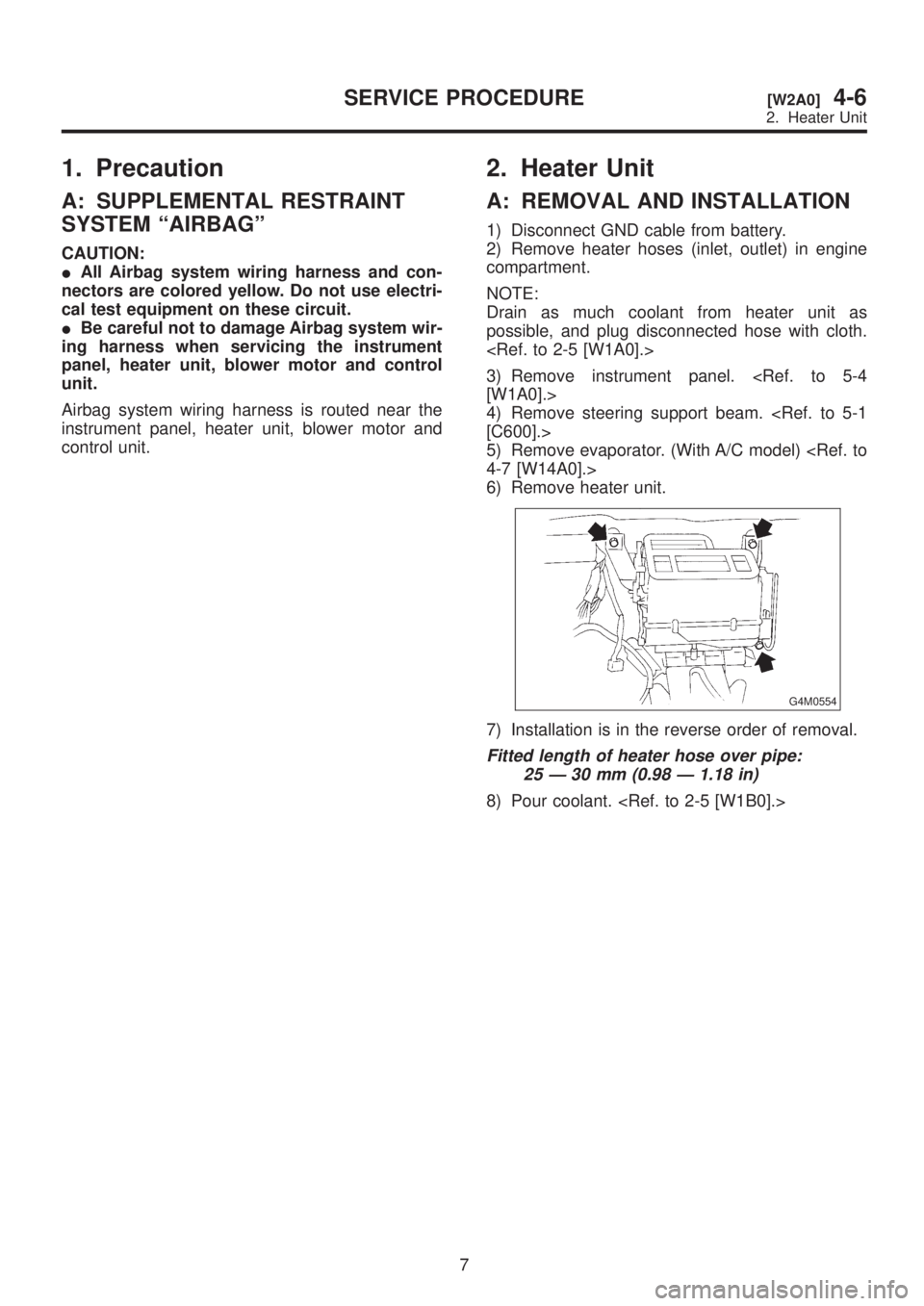
1) Disconnect GND cable from battery.
2) Remove heater hoses (inlet, outlet) in engine
compartment.
NOTE:
Drain as much coolant from heater unit as
possible, and plug disconnected hose with cloth.
3) Remove instrument panel.
[W1A0].>
4) Remove steering support beam.
[C600].>
5) Remove evaporator. (With A/C model)
4-7 [W14A0].>
6) Remove heater unit.
G4M0554
7) Installation is in the reverse order of removal.
Fitted length of heater hose over pipe:
25 Ð 30 mm (0.98 Ð 1.18 in)
8) Pour coolant.
7
[W2A0]4-6SERVICE PROCEDURE
2. Heater Unit