Page 171 of 1456

(5) Put new valve guide, coated with sufficient
oil, in cylinder, and insert ST1 into valve guide.
Press in until the valve guide upper end is flush
with the upper surface of ST2.
ST1 499767200 VALVE GUIDE REMOVER
ST2 498267700 VALVE GUIDE ADJUSTER
B2M1398A
(6) Check the valve guide protrusion.
Valve guide protrusion: L
12.0 Ð 12.4 mm (0.472 Ð 0.488 in)
(7) Ream the inside of valve guide with ST.
Gently rotate the reamer clockwise while press-
ing it lightly into valve guide, and return it also
rotating clockwise. After reaming, clean valve
guide to remove chips.
ST 499767400 VALVE GUIDE REAMER
CAUTION:
IApply engine oil to the reamer when ream-
ing.
IIf the inner surface of the valve guide is torn,
the edge of the reamer should be slightly
ground with an oil stone.
IIf the inner surface of the valve guide
becomes lustrous and the reamer does not
chips, use a new reamer or remedy the reamer.
(8) Recheck the contact condition between
valve and valve seat after replacing valve guide.
4. INTAKE AND EXHAUST VALVE
1) Inspect the flange and stem of valve, and
replace if damaged, worn, or deformed, or if ªHº is
less than the specified limit.
H:
Intake
Standard
1.2 mm (0.047 in)
Limit
0.8 mm (0.031 in)
Exhaust
Standard
1.5 mm (0.059 in)
Limit
0.8 mm (0.031 in))
Valve overall length:
Intake
105.9 mm (4.169 in)
Exhaust
106.2 mm (4.181 in)
G2M0153
2) Put a small amount of grinding compound on
the seat surface and lap the valve and seat sur-
face. Install a new intake valve oil seal after lap-
ping.
40
2-3b[W4C4]SERVICE PROCEDURE
4. Cylinder Head
Page 172 of 1456

5. VALVE SPRINGS
1) Check valve springs for damage, free length,
and tension. Replace valve spring if it is not to the
specifications presented in the table.
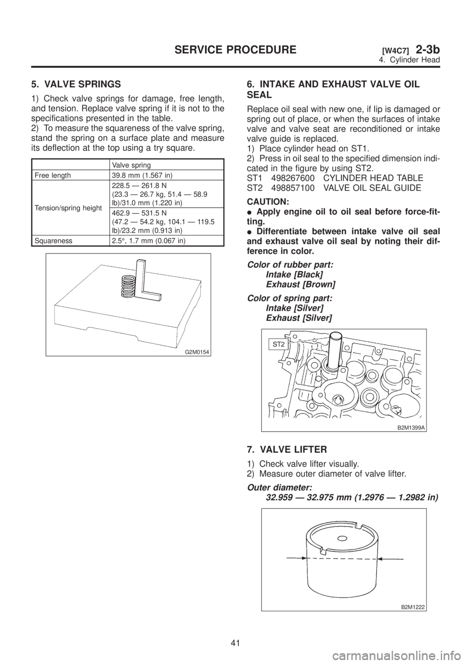
2) To measure the squareness of the valve spring,
stand the spring on a surface plate and measure
its deflection at the top using a try square.
Valve spring
Free length 39.8 mm (1.567 in)
Tension/spring height228.5 Ð 261.8 N
(23.3 Ð 26.7 kg, 51.4 Ð 58.9
lb)/31.0 mm (1.220 in)
462.9 Ð 531.5 N
(47.2 Ð 54.2 kg, 104.1 Ð 119.5
lb)/23.2 mm (0.913 in)
Squareness 2.5É, 1.7 mm (0.067 in)
G2M0154
6. INTAKE AND EXHAUST VALVE OIL
SEAL
Replace oil seal with new one, if lip is damaged or
spring out of place, or when the surfaces of intake
valve and valve seat are reconditioned or intake
valve guide is replaced.
1) Place cylinder head on ST1.
2) Press in oil seal to the specified dimension indi-
cated in the figure by using ST2.
ST1 498267600 CYLINDER HEAD TABLE
ST2 498857100 VALVE OIL SEAL GUIDE
CAUTION:
IApply engine oil to oil seal before force-fit-
ting.
IDifferentiate between intake valve oil seal
and exhaust valve oil seal by noting their dif-
ference in color.
Color of rubber part:
Intake [Black]
Exhaust [Brown]
Color of spring part:
Intake [Silver]
Exhaust [Silver]
B2M1399A
7. VALVE LIFTER
1) Check valve lifter visually.
2) Measure outer diameter of valve lifter.
Outer diameter:
32.959 Ð 32.975 mm (1.2976 Ð 1.2982 in)
B2M1222
41
[W4C7]2-3bSERVICE PROCEDURE
4. Cylinder Head
Page 190 of 1456

5. CONNECTING ROD
1) Replace connecting rod, if the large or small
end thrust surface is damaged.
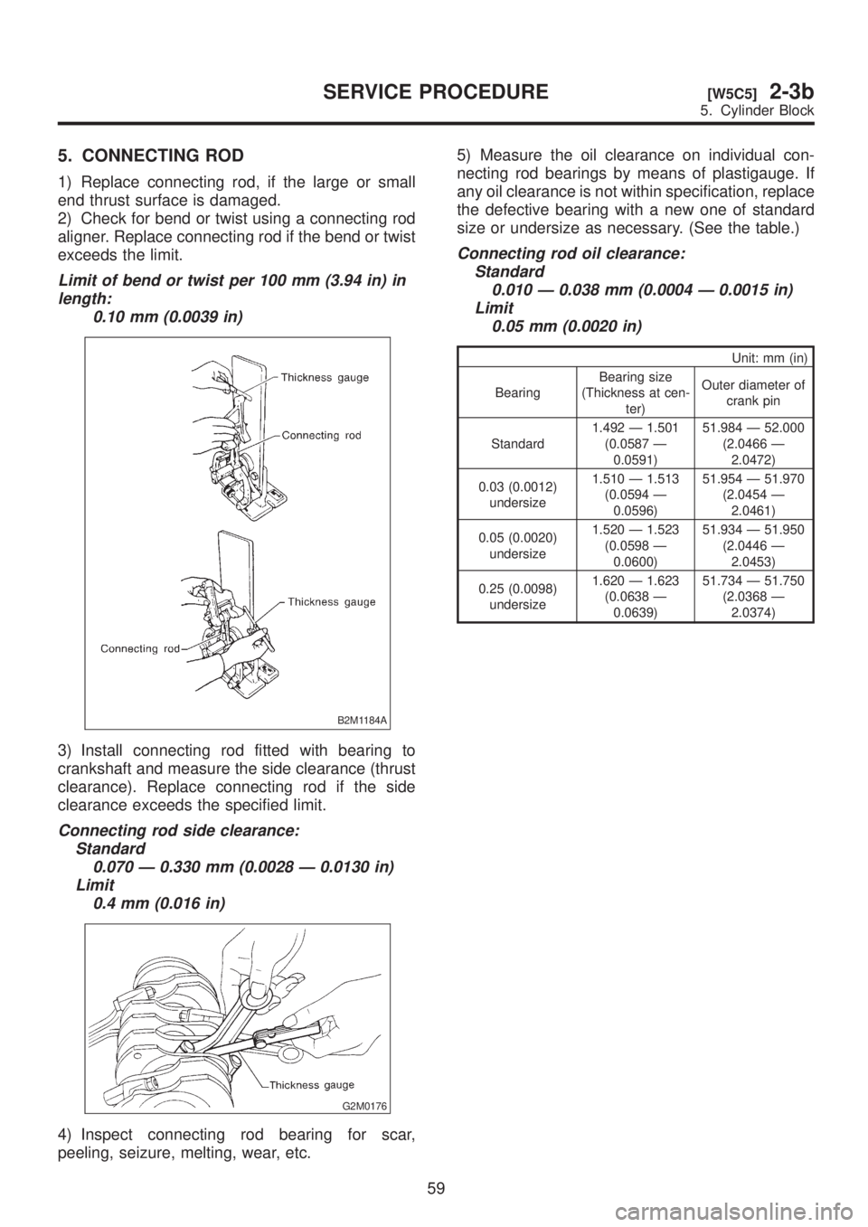
2) Check for bend or twist using a connecting rod
aligner. Replace connecting rod if the bend or twist
exceeds the limit.
Limit of bend or twist per 100 mm (3.94 in) in
length:
0.10 mm (0.0039 in)
B2M1184A
3) Install connecting rod fitted with bearing to
crankshaft and measure the side clearance (thrust
clearance). Replace connecting rod if the side
clearance exceeds the specified limit.
Connecting rod side clearance:
Standard
0.070 Ð 0.330 mm (0.0028 Ð 0.0130 in)
Limit
0.4 mm (0.016 in)
G2M0176
4) Inspect connecting rod bearing for scar,
peeling, seizure, melting, wear, etc.5) Measure the oil clearance on individual con-
necting rod bearings by means of plastigauge. If
any oil clearance is not within specification, replace
the defective bearing with a new one of standard
size or undersize as necessary. (See the table.)
Connecting rod oil clearance:
Standard
0.010 Ð 0.038 mm (0.0004 Ð 0.0015 in)
Limit
0.05 mm (0.0020 in)
Unit: mm (in)
BearingBearing size
(Thickness at cen-
ter)Outer diameter of
crank pin
Standard1.492 Ð 1.501
(0.0587 Ð
0.0591)51.984 Ð 52.000
(2.0466 Ð
2.0472)
0.03 (0.0012)
undersize1.510 Ð 1.513
(0.0594 Ð
0.0596)51.954 Ð 51.970
(2.0454 Ð
2.0461)
0.05 (0.0020)
undersize1.520 Ð 1.523
(0.0598 Ð
0.0600)51.934 Ð 51.950
(2.0446 Ð
2.0453)
0.25 (0.0098)
undersize1.620 Ð 1.623
(0.0638 Ð
0.0639)51.734 Ð 51.750
(2.0368 Ð
2.0374)
59
[W5C5]2-3bSERVICE PROCEDURE
5. Cylinder Block
Page 215 of 1456

3. SIDE CLEARANCE
Measure clearance between oil pump inner rotor
and pump cover. If the clearance exceeds the limit,
replace rotor or pump body.
Side clearance:
Standard
0.02 Ð 0.07 mm (0.0008 Ð 0.0028 in)
Limit
0.15 mm (0.0059 in)
B2M1915
4. OIL RELIEF VALVE
Check the valve for fitting condition and damage,
and the relief valve spring for damage and deterio-
ration. Replace the parts if defective.
Relief valve spring:
Free length; 71.8 mm (2.827 in)
Installed length; 54.7 mm (2.154 in)
Load when installed; 77.08 N (7.86 kg,
17.33 lb)
5. OIL PUMP CASE
Check the oil pump case for worn shaft hole,
clogged oil passage, worn rotor chamber, cracks,
and other faults.
6. OIL SEAL
Check the oil seal lips for deformation, hardening,
wear, etc. and replace if defective.
D: ASSEMBLY
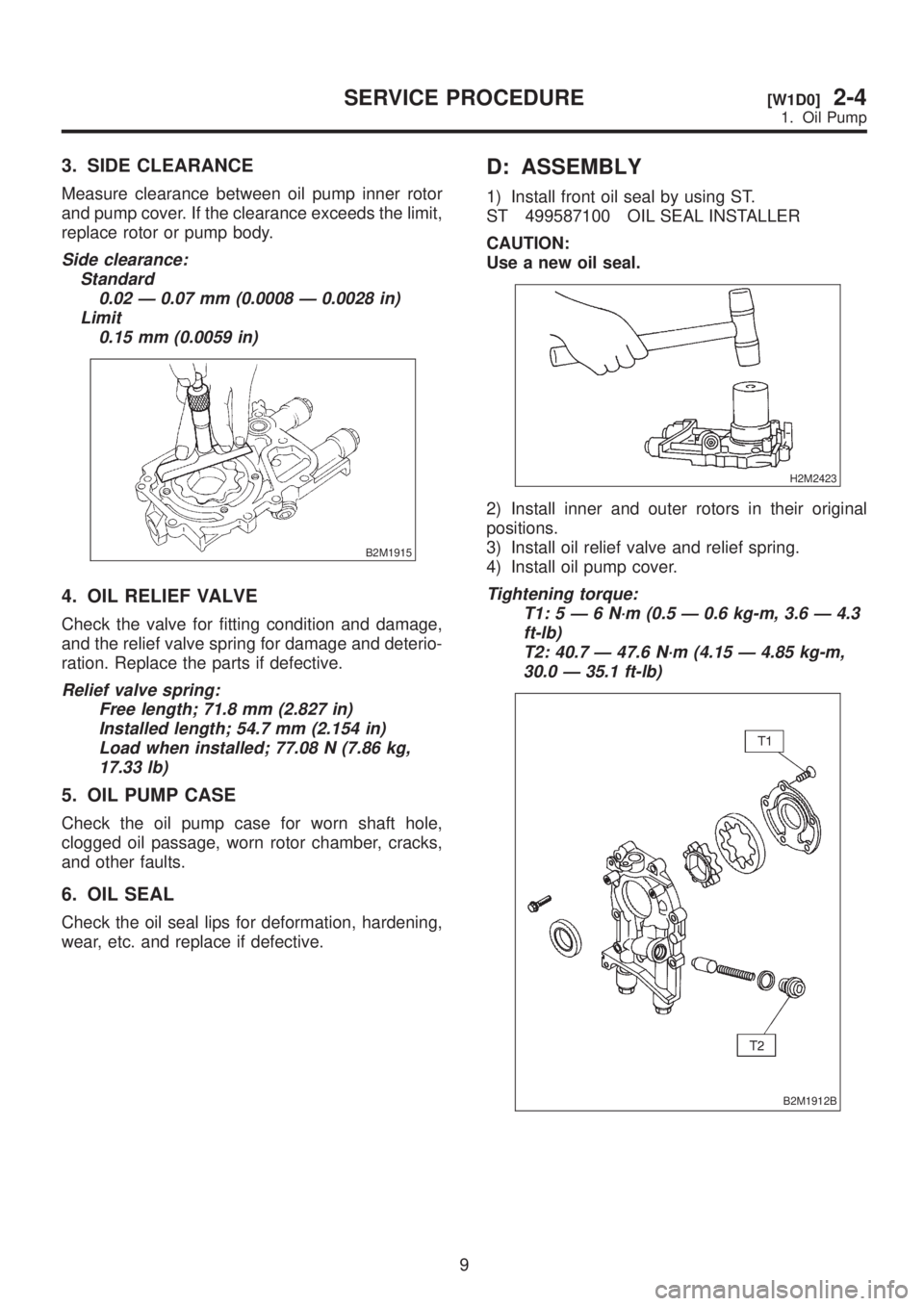
1) Install front oil seal by using ST.
ST 499587100 OIL SEAL INSTALLER
CAUTION:
Use a new oil seal.
H2M2423
2) Install inner and outer rotors in their original
positions.
3) Install oil relief valve and relief spring.
4) Install oil pump cover.
Tightening torque:
T1:5Ð6N´m(0.5 Ð 0.6 kg-m, 3.6 Ð 4.3
ft-lb)
T2: 40.7 Ð 47.6 N´m (4.15 Ð 4.85 kg-m,
30.0 Ð 35.1 ft-lb)
B2M1912B
9
[W1D0]2-4SERVICE PROCEDURE
1. Oil Pump
Page 375 of 1456
B2M1744B
5) Install hose and hold down clips at positions
indicated in Figure.
Tightening torque:
1.0+0.5/þ0N´m (0.1+0.05/þ0kg-m, 0.7+0.4/þ0ft-lb)
Type A: When fitting length is specified.
Type B: When fitting length is not specified.
: 1.0 Ð 4.0 mm (0.039 Ð 0.157 in)
L: 20 Ð 25 mm (0.79 Ð 0.98 in)
B2M1194C
(1) Fitting
(2) Clamp
(3) Hose
Fuel return hose:
L = 20 Ð 25 mm (0.79 Ð 0.98 in)
Evaporation hose:
L = 15 Ð 20 mm (0.59 Ð 0.79 in)
B2M1195A
(1) Hose
(2) Clip
(3) Pipe
6) Tighten band mounting bolts.
Tightening torque:
33
±10 N´m (3.4±1.0 kg-m, 25±7 ft-lb)
S2M0169A
7) Install rear crossmember.
[W10C0].>
G4M0545
8) Install rear differential assembly.
[W2F0].>
G3M0059
9) Connect connector to drain valve.
B2M1743
13
[W2B0]2-8SERVICE PROCEDURE
2. Fuel Tank
Page 389 of 1456

B: INSTALLATION
Installation is in the reverse order of removal.
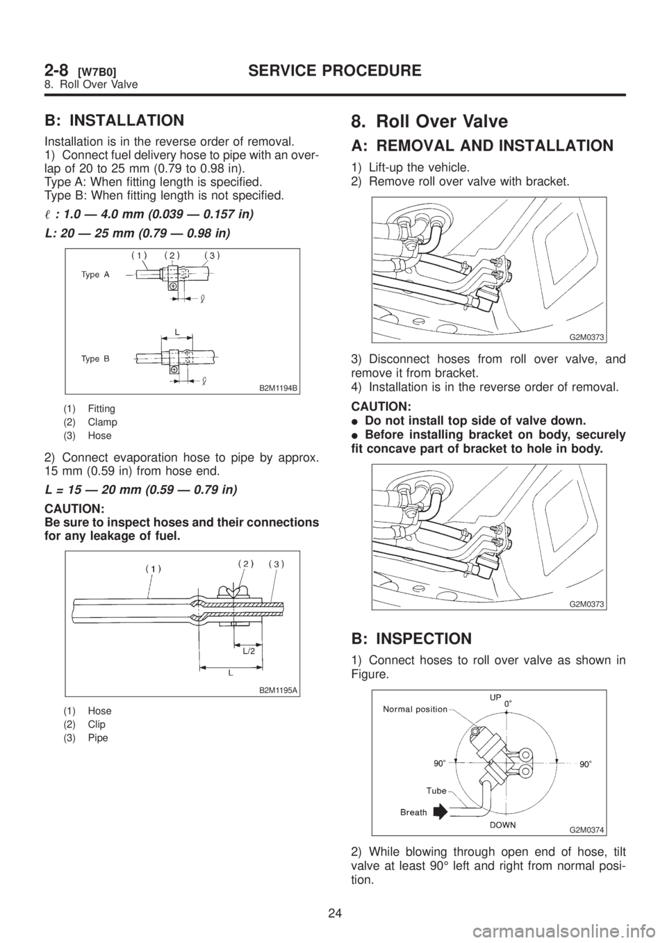
1) Connect fuel delivery hose to pipe with an over-
lap of 20 to 25 mm (0.79 to 0.98 in).
Type A: When fitting length is specified.
Type B: When fitting length is not specified.
: 1.0 Ð 4.0 mm (0.039 Ð 0.157 in)
L: 20 Ð 25 mm (0.79 Ð 0.98 in)
B2M1194B
(1) Fitting
(2) Clamp
(3) Hose
2) Connect evaporation hose to pipe by approx.
15 mm (0.59 in) from hose end.
L = 15 Ð 20 mm (0.59 Ð 0.79 in)
CAUTION:
Be sure to inspect hoses and their connections
for any leakage of fuel.
B2M1195A
(1) Hose
(2) Clip
(3) Pipe
8. Roll Over Valve
A: REMOVAL AND INSTALLATION
1) Lift-up the vehicle.
2) Remove roll over valve with bracket.
G2M0373
3) Disconnect hoses from roll over valve, and
remove it from bracket.
4) Installation is in the reverse order of removal.
CAUTION:
IDo not install top side of valve down.
IBefore installing bracket on body, securely
fit concave part of bracket to hole in body.
G2M0373
B: INSPECTION
1) Connect hoses to roll over valve as shown in
Figure.
G2M0374
2) While blowing through open end of hose, tilt
valve at least 90É left and right from normal posi-
tion.
24
2-8[W7B0]SERVICE PROCEDURE
8. Roll Over Valve
Page 390 of 1456

B: INSTALLATION
Installation is in the reverse order of removal.
1) Connect fuel delivery hose to pipe with an over-
lap of 20 to 25 mm (0.79 to 0.98 in).
Type A: When fitting length is specified.
Type B: When fitting length is not specified.
: 1.0 Ð 4.0 mm (0.039 Ð 0.157 in)
L: 20 Ð 25 mm (0.79 Ð 0.98 in)
B2M1194B
(1) Fitting
(2) Clamp
(3) Hose
2) Connect evaporation hose to pipe by approx.
15 mm (0.59 in) from hose end.
L = 15 Ð 20 mm (0.59 Ð 0.79 in)
CAUTION:
Be sure to inspect hoses and their connections
for any leakage of fuel.
B2M1195A
(1) Hose
(2) Clip
(3) Pipe
8. Roll Over Valve
A: REMOVAL AND INSTALLATION
1) Lift-up the vehicle.
2) Remove roll over valve with bracket.
G2M0373
3) Disconnect hoses from roll over valve, and
remove it from bracket.
4) Installation is in the reverse order of removal.
CAUTION:
IDo not install top side of valve down.
IBefore installing bracket on body, securely
fit concave part of bracket to hole in body.
G2M0373
B: INSPECTION
1) Connect hoses to roll over valve as shown in
Figure.
G2M0374
2) While blowing through open end of hose, tilt
valve at least 90É left and right from normal posi-
tion.
24
2-8[W7B0]SERVICE PROCEDURE
8. Roll Over Valve
Page 595 of 1456

(2) Using ST, measure the distance from the oil
pump housing mating surface to the top surface
of the oil pump cover with thrust needle bearing.
ST 398643600 GAUGE
B3M0983A
(3) Calculation of total end play
Select suitable bearing race from among those
listed in this table so that clearance C is in the
0.25 Ð 0.55 mm (0.0098 Ð 0.0217 in) range.
C=(L+G)þ
CClearance between concave portion of high clutch
and end of clutch drum support
LLength from case mating surface to concave por-
tion of high clutch
G Gasket thickness (0.28 mm, 0.0110 in)
Height from housing mating surface to upper sur-
face of clutch drum support
B3M0984A
Thrust needle bearing
Part No. Thickness mm (in)
806528050
806528060
806528070
806528080
806528090
8065281004.1 (0.161)
4.3 (0.169)
4.5 (0.177)
4.7 (0.185)
4.9 (0.193)
5.1 (0.201)
27) Install the oil pump housing assembly.
(1) After completing end play adjustment, insert
the bearing race in the recess of the high clutch.
Attach the thrust needle bearing to the oil pump
cover with vaseline.(2) After correctly installing the gasket to the
case mating surface, carefully install the oil
pump housing assembly. Be careful to avoid hit-
ting the drive pinion against the inside of the
case.
CAUTION:
IBe careful not to damage the seal ring.
IBe sure to use a new gasket.
(3) Install both parts with dowel pins aligned.
Make sure no clearance exists at the mating
surface.
NOTE:
Any clearance suggests a damaged seal ring.
(4) Secure the housing with two nuts.
Tightening torque:
T: 4 1
±3 N´m (4.2±0.3 kg-m, 30.4±2.2 ft-lb)
B3M1068A
3. TORQUE CONVERTER CLUTCH CASE
AND TRANSMISSION CASE
1) Apply proper amount of liquid gasket (THREE
BOND Part No. 1215) to the entire torque con-
verter clutch case mating surface.
NOTE:
Make sure that the rubber seal and seal pipe are
fitted in position.
G3M0394
66
3-2[W11C3]SERVICE PROCEDURE
11. Overall Transmission