1999 SUBARU LEGACY length
[x] Cancel search: lengthPage 600 of 1456

7. EXTERNAL PARTS
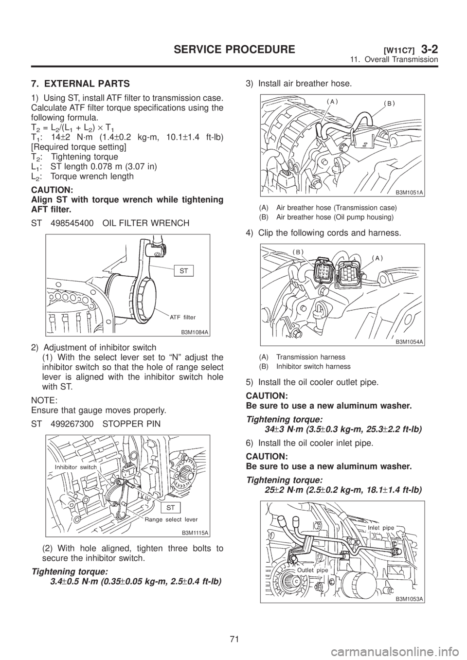
1) Using ST, install ATF filter to transmission case.
Calculate ATF filter torque specifications using the
following formula.
T
2=L2/(L1+L2)´T1T1:14±2 N´m (1.4±0.2 kg-m, 10.1±1.4 ft-lb)
[Required torque setting]
T
2: Tightening torque
L
1: ST length 0.078 m (3.07 in)
L
2: Torque wrench length
CAUTION:
Align ST with torque wrench while tightening
AFT filter.
ST 498545400 OIL FILTER WRENCH
B3M1084A
2) Adjustment of inhibitor switch
(1) With the select lever set to ªNº adjust the
inhibitor switch so that the hole of range select
lever is aligned with the inhibitor switch hole
with ST.
NOTE:
Ensure that gauge moves properly.
ST 499267300 STOPPER PIN
B3M1115A
(2) With hole aligned, tighten three bolts to
secure the inhibitor switch.
Tightening torque:
3.4
±0.5 N´m (0.35±0.05 kg-m, 2.5±0.4 ft-lb)
3) Install air breather hose.
B3M1051A
(A) Air breather hose (Transmission case)
(B) Air breather hose (Oil pump housing)
4) Clip the following cords and harness.
B3M1054A
(A) Transmission harness
(B) Inhibitor switch harness
5) Install the oil cooler outlet pipe.
CAUTION:
Be sure to use a new aluminum washer.
Tightening torque:
34
±3 N´m (3.5±0.3 kg-m, 25.3±2.2 ft-lb)
6) Install the oil cooler inlet pipe.
CAUTION:
Be sure to use a new aluminum washer.
Tightening torque:
25
±2 N´m (2.5±0.2 kg-m, 18.1±1.4 ft-lb)
B3M1053A
71
[W11C7]3-2SERVICE PROCEDURE
11. Overall Transmission
Page 606 of 1456

No. Part nameWire dia.
mm (in)Average dia.
mm (in)Effective turnFree length
mm (in)
332-4 brake accumulator B spring
(Inlet)1.6 (0.063) 9.3 (0.366) 14.6 47.0 (1.850)
342-4 brake accumulator B spring
(Outlet)2.3 (0.091) 13.7 (0.539) 8.79 45.0 (1.772)
352-4 brake accumulator A spring
(Inlet)1.8 (0.071) 21.3 (0.839) 8.0 69.1 (2.720)
362-4 brake accumulator A spring
(Outlet)1.7 (0.067) 25.3 (0.996) 6.3 69.1 (2.720)
37Low clutch accumulator spring
(Inlet)1.8 (0.071) 21.3 (0.839) 8.0 69.1 (2.720)
38Low clutch accumulator spring
(Outlet)1.7 (0.067) 25.3 (0.996) 6.3 69.1 (2.720)
39High clutch accumulator A spring
(Inlet)1.8 (0.071) 21.3 (0.839) 8.0 69.1 (2.720)
40High clutch accumulator A spring
(Outlet)1.7 (0.067) 25.3 (0.996) 6.3 69.1 (2.720)
41High clutch accumulator B spring
(Inlet)1.6 (0.063) 9.3 (0.366) 14.6 47.0 (1.850)
42High clutch accumulator B spring
(Outlet)2.3 (0.091) 13.7 (0.539) 8.79 45.0 (1.772)
43 Pressure regulator valve spring 1.0 (0.039) 13.5 (0.531) 6.5 35.0 (1.378)
44 Reverse inhibit valve spring 0.65 (0.0256) 8.4 (0.331) 7.7 26.5 (1.043)
45 Accumulator control valve B spring 0.5 (0.020) 10.5 (0.413) 4.5 21.5 (0.846)
46 2-4 brake timing valve A spring 0.80 (0.0315) 8.2 (0.323) 7.9 25.2 (0.992)
47 2-4 brake timing valve B spring 0.60 (0.0236) 5.8 (0.228) 7.7 20.0 (0.787)
48Torque converter regulator valve
spring1.40 (0.0551) 7.6 (0.299) 12.1 34.7 (1.366)
49Torque converter one-way valve
spring0.8 (0.031) 9.7 (0.382) 11.5 40.0 (1.575)
50 Pressure modifier valve spring 0.7 (0.028) 8.3 (0.327) 8.2 26.9 (1.059)
51 Accumulator control valve A 0.7 (0.028) 10.3 (0.406) 3.6 15.1 (0.594)
52 Low clutch timing valve A spring 0.5 (0.020) 6.5 (0.256) 7.78 19.3 (0.760)
53 Low clutch timing valve B spring 0.60 (0.0236) 5.8 (0.228) 7.7 20.0 (0.787)
54 Shift valve B spring 0.80 (0.0315) 8.2 (0.323) 7.9 25.2 (0.992)
55 Shift valve A spring 0.80 (0.0315) 8.2 (0.323) 7.9 25.2 (0.992)
56 Throttle accumulator B spring 1.6 (0.063) 8.4 (0.331) 9.77 36.0 (1.417)
57 1st reducing valve spring 0.75 (0.0295) 6.0 (0.236) 12.5 25.4 (1.000)
58 Throttle accumulator A spring 1.7 (0.067) 8.0 (0.315) 9.61 36.0 (1.417)
59 Lock-up control valve spring 0.9 (0.035) 11.2 (0.441) 4.0 19.7 (0.776)
60 Modifier accumulator spring 1.7 (0.067) 8.0 (0.315) 9.61 36.0 (1.417)
61 Line pressure relief valve spring 1.6 (0.063) 8.0 (0.315) 22.5 69.3 (2.728)
62 Pilot valve spring 1.1 (0.043) 7.9 (0.311) 10.76 30.6 (1.205)
77
[W14A0]3-2SERVICE PROCEDURE
14. Control Valve Body
Page 648 of 1456

E: INSTALLATION
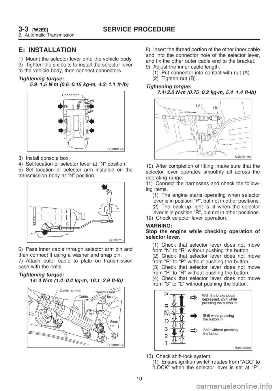
1) Mount the selector lever onto the vehicle body.
2) Tighten the six bolts to install the selector lever
to the vehicle body, then connect connectors.
Tightening torque:
5.9
±1.5 N´m (0.6±0.15 kg-m, 4.3±1.1 ft-lb)
S3M0017A
3) Install console box.
4) Set location of selector lever at ªNº position.
5) Set location of selector arm installed on the
transmission body at ªNº position.
G3M0715
6) Pass inner cable through selector arm pin and
then connect it using a washer and snap pin.
7) Attach outer cable to plate on transmission
case with the bolts.
Tightening torque:
14
±4 N´m (1.4±0.4 kg-m, 10.1±2.9 ft-lb)
S3M0016A
8) Insert the thread portion of the other inner cable
and into the connector hole of the selector lever,
and fix the other outer cable end to the bracket.
9) Adjust the inner cable length.
(1) Put connector into contact with nut (A).
(2) Tighten nut (B).
Tightening torque:
7.4
±2.0 N´m (0.75±0.2 kg-m, 5.4±1.4 ft-lb)
S3M0019A
10) After completion of fitting, make sure that the
selector lever operates smoothly all across the
operating range.
11) Connect the harnesses and check the follow-
ing items.
(1) The engine starts operating when selector
lever is in position ªPº, but not in other positions.
(2) The back-up light is lit when the selector
lever is in position ªRº, but not in other positions.
12) Check selector lever operation.
WARNING:
Stop the engine while checking operation of
selector lever.
(1) Check that selector lever does not move
from ªNº to ªRº without pushing the button.
(2) Check that selector lever does not move
from ªRº to ªPº without pushing the button.
(3) Check that selector lever does not move
from ªPº to ªRº without pushing the button.
(4) Check that selector lever does not move
from ª3º to ª2º without pushing the button.
B3M0348A
13) Check shift-lock system.
(1) Ensure ignition switch rotates from ªACCº to
ªLOCKº when the selector lever is set at ªPº.
10
3-3[W2E0]SERVICE PROCEDURE
2. Automatic Transmission
Page 651 of 1456

1. Propeller Shaft
A: SPECIFICATIONS
Front propeller shaft Joint-to-joint length: L1mm (in)AT 693 (27.28)
MT 634 (24.96)
Rear propeller shaft Joint-to-joint
length: L
2mm (in)768 (30.24)
Outside dia. of tube mm (in)D
163.5 (2.500)
D
257.0 (2.244)
B3M0851A
2
3-4[S1A0]SPECIFICATIONS AND SERVICE DATA
1. Propeller Shaft
Page 653 of 1456

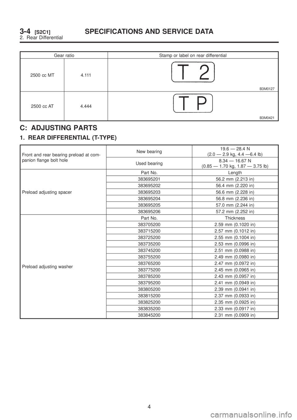
Gear ratio Stamp or label on rear differential
2500 cc MT 4.111
B3M0127
2500 cc AT 4.444
B3M0421
C: ADJUSTING PARTS
1. REAR DIFFERENTIAL (T-TYPE)
Front and rear bearing preload at com-
panion flange bolt holeNew bearing19.6 Ð 28.4 N
(2.0 Ð 2.9 kg, 4.4 Ð6.4 lb)
Used bearing8.34 Ð 16.67 N
(0.85 Ð 1.70 kg, 1.87 Ð 3.75 lb)
Preload adjusting spacerPart No. Length
383695201 56.2 mm (2.213 in)
383695202 56.4 mm (2.220 in)
383695203 56.6 mm (2.228 in)
383695204 56.8 mm (2.236 in)
383695205 57.0 mm (2.244 in)
383695206 57.2 mm (2.252 in)
Preload adjusting washerPart No. Thickness
383705200 2.59 mm (0.1020 in)
383715200 2.57 mm (0.1012 in)
383725200 2.55 mm (0.1004 in)
383735200 2.53 mm (0.0996 in)
383745200 2.51 mm (0.0988 in)
383755200 2.49 mm (0.0980 in)
383765200 2.47 mm (0.0972 in)
383775200 2.45 mm (0.0965 in)
383785200 2.43 mm (0.0957 in)
383795200 2.41 mm (0.0949 in)
383805200 2.39 mm (0.0941 in)
383815200 2.37 mm (0.0933 in)
383825200 2.35 mm (0.0925 in)
383835200 2.33 mm (0.0917 in)
383845200 2.31 mm (0.0909 in)
4
3-4[S2C1]SPECIFICATIONS AND SERVICE DATA
2. Rear Differential
Page 654 of 1456

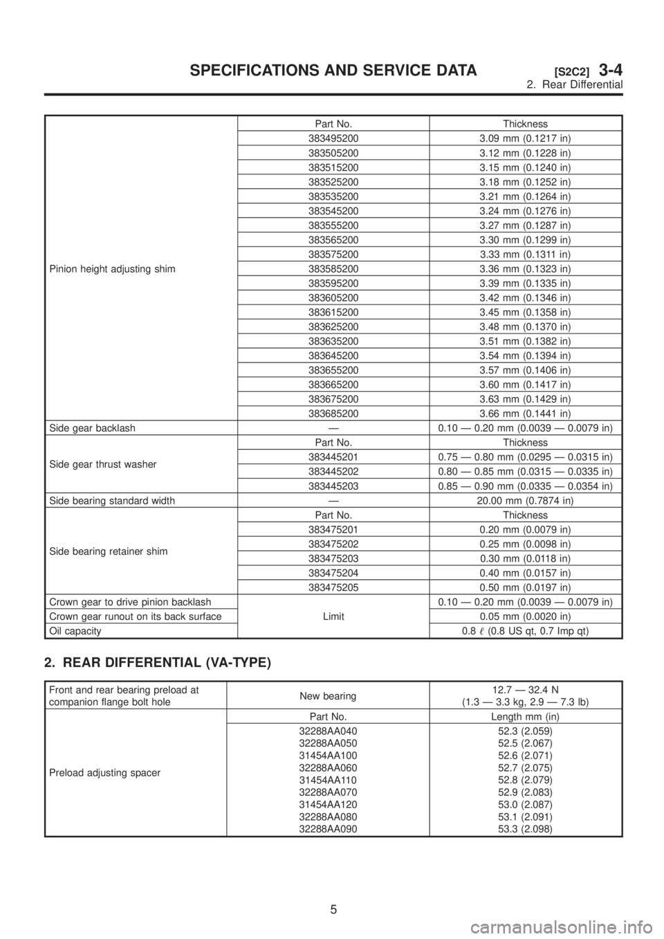
Pinion height adjusting shimPart No. Thickness
383495200 3.09 mm (0.1217 in)
383505200 3.12 mm (0.1228 in)
383515200 3.15 mm (0.1240 in)
383525200 3.18 mm (0.1252 in)
383535200 3.21 mm (0.1264 in)
383545200 3.24 mm (0.1276 in)
383555200 3.27 mm (0.1287 in)
383565200 3.30 mm (0.1299 in)
383575200 3.33 mm (0.1311 in)
383585200 3.36 mm (0.1323 in)
383595200 3.39 mm (0.1335 in)
383605200 3.42 mm (0.1346 in)
383615200 3.45 mm (0.1358 in)
383625200 3.48 mm (0.1370 in)
383635200 3.51 mm (0.1382 in)
383645200 3.54 mm (0.1394 in)
383655200 3.57 mm (0.1406 in)
383665200 3.60 mm (0.1417 in)
383675200 3.63 mm (0.1429 in)
383685200 3.66 mm (0.1441 in)
Side gear backlash Ð 0.10 Ð 0.20 mm (0.0039 Ð 0.0079 in)
Side gear thrust washerPart No. Thickness
383445201 0.75 Ð 0.80 mm (0.0295 Ð 0.0315 in)
383445202 0.80 Ð 0.85 mm (0.0315 Ð 0.0335 in)
383445203 0.85 Ð 0.90 mm (0.0335 Ð 0.0354 in)
Side bearing standard width Ð 20.00 mm (0.7874 in)
Side bearing retainer shimPart No. Thickness
383475201 0.20 mm (0.0079 in)
383475202 0.25 mm (0.0098 in)
383475203 0.30 mm (0.0118 in)
383475204 0.40 mm (0.0157 in)
383475205 0.50 mm (0.0197 in)
Crown gear to drive pinion backlash
Limit0.10 Ð 0.20 mm (0.0039 Ð 0.0079 in)
Crown gear runout on its back surface 0.05 mm (0.0020 in)
Oil capacity0.8(0.8 US qt, 0.7 Imp qt)
2. REAR DIFFERENTIAL (VA-TYPE)
Front and rear bearing preload at
companion flange bolt holeNew bearing12.7 Ð 32.4 N
(1.3 Ð 3.3 kg, 2.9 Ð 7.3 lb)
Preload adjusting spacerPart No. Length mm (in)
32288AA040
32288AA050
31454AA100
32288AA060
31454AA110
32288AA070
31454AA120
32288AA080
32288AA09052.3 (2.059)
52.5 (2.067)
52.6 (2.071)
52.7 (2.075)
52.8 (2.079)
52.9 (2.083)
53.0 (2.087)
53.1 (2.091)
53.3 (2.098)
5
[S2C2]3-4SPECIFICATIONS AND SERVICE DATA
2. Rear Differential
Page 682 of 1456

(4) Turn ST1 with hand to make it seated, and
tighten drive pinion nut while measuring the pre-
load with spring balance. Select preload adjust-
ing washer and spacer so that the specified pre-
load is obtained when nut is tightened to the
specified torque with ST2.
ST1 398507704 BLOCK
ST2 398507702 DUMMY SHAFT
CAUTION:
Use a new lock nut.
NOTE:
IBe careful not to give excessive preload.
IWhen tightening the drive pinion nut, lock ST1
with ST2 as shown in the figure.
Tightening torque:
181
±15 N´m (18.5±1.5 kg-m, 134±11 ft-lb)
G3M1038
Front and rear bearing preload
For new bearing:
17.7 Ð 25.5 N (1.8 Ð 2.6 kg, 4.0 Ð 5.7 lb)
at companion flange bolt hole
G3M0082
Preload adjusting
washerPart No. Thickness mm (in)
383705200 2.59 (0.1020)
383715200 2.57 (0.1012)
383725200 2.55 (0.1004)
383735200 2.53 (0.0996)
383745200 2.51 (0.0988)
383755200 2.49 (0.0980)
383765200 2.47 (0.0972)
383775200 2.45 (0.0965)
383785200 2.43 (0.0957)
383795200 2.41 (0.0949)
383805200 2.39 (0.0941)
383815200 2.37 (0.0933)
383825200 2.35 (0.0925)
383835200 2.33 (0.0917)
383845200 2.31 (0.0909)
Preload adjusting
spacerPart No. Length mm (in)
383695201 56.2 (2.213)
383695202 56.4 (2.220)
383695203 56.6 (2.228)
383695204 56.8 (2.236)
383695205 57.0 (2.244)
383695206 57.2 (2.252)
3) Adjusting drive pinion height
Adjust drive pinion height with shim installed
between rear bearing cone and the back of pinion
gear.
32
3-4[W2E1]SERVICE PROCEDURE
2. Rear Differential
Page 690 of 1456

(6) Turn ST1 with hand to make it seated, and
tighten drive pinion nut while measuring the pre-
load with spring balance. Select preload adjust-
ing washer and spacer so that the specified pre-
load is obtained when nut is tightened to the
specified torque with ST2.
CAUTION:
Use a new lock nut.
NOTE:
IBe careful not to give excessive preload.
IWhen tightening the drive pinion nut, lock ST1
with ST2.
ST1 398507704 BLOCK
ST2 498447150 DUMMY SHAFT
Tightening torque:
188
±26 N´m (19.2±2.7 kg-m, 139±20 ft-lb)
G3M1038
Front and rear bearing preload
For new bearing:
12.7 Ð 32.4 N (1.3 Ð 3.3 kg, 2.9 Ð 7.3 lb)
at companion flange bolt hole
G3M0082
Preload adjusting
washerPart No. Thickness mm (in)
38336AA000
38336AA120
38336AA010
38336AA130
38336AA020
38336AA140
38336AA030
38336AA150
38336AA040
38336AA160
38336AA050
38336AA170
38336AA060
38336AA180
38336AA070
38336AA190
38336AA080
38336AA200
38336AA090
38336AA210
38336AA100
38336AA220
38336AA1101.500 (0.0591)
1.513 (0.0596)
1.525 (0.0600)
1.538 (0.0606)
1.550 (0.0610)
1.563 (0.0615)
1.575 (0.0620)
1.588 (0.0625)
1.600 (0.0630)
1.613 (0.0635)
1.625 (0.0640)
1.638 (0.0645)
1.650 (0.0650)
1.663 (0.0655)
1.675 (0.0659)
1.688 (0.0665)
1.700 (0.0669)
1.713 (0.0674)
1.725 (0.0679)
1.738 (0.0684)
1.750 (0.0689)
1.763 (0.0694)
1.775 (0.0699)
Preload adjusting
spacerPart No. Length mm (in)
32288AA040
32288AA050
31454AA100
32288AA060
31454AA110
32288AA070
31454AA120
32288AA080
32288AA09052.3 (2.059)
52.5 (2.067)
52.6 (2.071)
52.7 (2.075)
52.8 (2.079)
52.9 (2.083)
53.0 (2.087)
53.1 (2.091)
53.3 (2.098)
3) Adjusting drive pinion height Adjust drive pinion
height with shim installed between rear bearing
cone and the back of pinion gear.
(1) Install ST1, ST2 and ST3, as shown in the
figure, and apply the specified preload on the
bearings.
Front and rear bearing preload
For new bearing:
12.7 Ð 32.4 N (1.3 Ð 3.3 kg, 2.9 Ð 7.3 lb)
at companion flange bolt hole
40
3-4[W2E2]SERVICE PROCEDURE
2. Rear Differential