1999 SUBARU LEGACY torque specifications
[x] Cancel search: torque specificationsPage 942 of 1456

4) Install front ABS sensor on strut and wheel
apron bracket.
Tightening torque:
32
±10 N´m (3.3±1.0 kg-m, 24±7 ft-lb)
B4M1442A
5) Place a thickness gauge between ABS sensor's
pole piece and tone wheel's tooth face. After stan-
dard clearance is obtained over the entire
perimeter, tighten ABS sensor on housing to speci-
fied torque.
ABS sensor standard clearance:
0.9 Ð 1.4 mm (0.035 Ð 0.055 in)
Tightening torque:
32
±10 N´m (3.3±1.0 kg-m, 24±7 ft-lb)
CAUTION:
Check the marks on the harness to make sure
that no distortion exists. (RH: white, LH: yel-
low)
NOTE:
If the clearance is outside specifications, readjust.
17. Brake Pipe
A: SUPPLEMENTAL RESTRAINT
SYSTEM ªAIRBAGº
Airbag system wiring harness is routed near the
center brake pipe.
CAUTION:
IAll Airbag system wiring harness and con-
nectors are colored yellow. Do not use electri-
cal test equipment on these circuit.
IBe careful not to damage Airbag system wir-
ing harness when servicing the center brake
pipe.
B: REMOVAL AND INSTALLATION
CAUTION:
IWhen removing and installing the brake
pipe, make sure that it is not bent.
IAfter installing the brake pipe and hose,
bleed the air.
IAfter installing the brake hose, make sure
that it does not touch the tire or suspension
assembly, etc.
Brake pipe tightening torque:
15+3/þ2N´m (1.5+0.3/þ0.2kg-m, 10.8+2.2/þ1.4ft-lb)
63
[W17B0]4-4SERVICE PROCEDURE
17. Brake Pipe
Page 956 of 1456
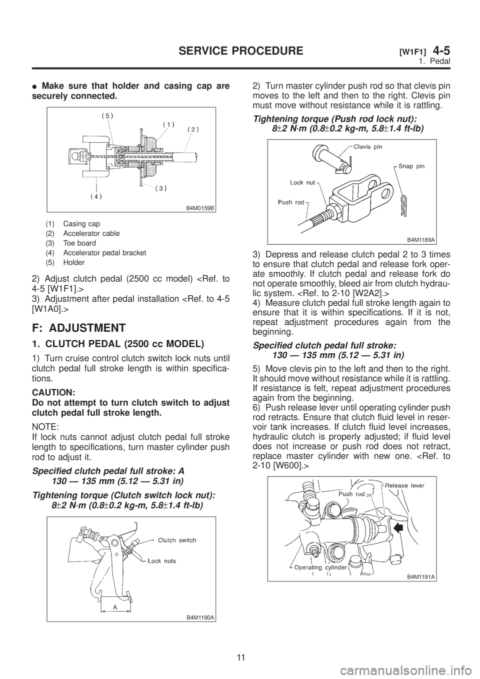
IMake sure that holder and casing cap are
securely connected.
B4M0159B
(1) Casing cap
(2) Accelerator cable
(3) Toe board
(4) Accelerator pedal bracket
(5) Holder
2) Adjust clutch pedal (2500 cc model)
3) Adjustment after pedal installation
F: ADJUSTMENT
1. CLUTCH PEDAL (2500 cc MODEL)
1) Turn cruise control clutch switch lock nuts until
clutch pedal full stroke length is within specifica-
tions.
CAUTION:
Do not attempt to turn clutch switch to adjust
clutch pedal full stroke length.
NOTE:
If lock nuts cannot adjust clutch pedal full stroke
length to specifications, turn master cylinder push
rod to adjust it.
Specified clutch pedal full stroke: A
130 Ð 135 mm (5.12 Ð 5.31 in)
Tightening torque (Clutch switch lock nut):
8
±2 N´m (0.8±0.2 kg-m, 5.8±1.4 ft-lb)
B4M1190A
2) Turn master cylinder push rod so that clevis pin
moves to the left and then to the right. Clevis pin
must move without resistance while it is rattling.
Tightening torque (Push rod lock nut):
8
±2 N´m (0.8±0.2 kg-m, 5.8±1.4 ft-lb)
B4M1189A
3) Depress and release clutch pedal 2 to 3 times
to ensure that clutch pedal and release fork oper-
ate smoothly. If clutch pedal and release fork do
not operate smoothly, bleed air from clutch hydrau-
lic system.
4) Measure clutch pedal full stroke length again to
ensure that it is within specifications. If it is not,
repeat adjustment procedures again from the
beginning.
Specified clutch pedal full stroke:
130 Ð 135 mm (5.12 Ð 5.31 in)
5) Move clevis pin to the left and then to the right.
It should move without resistance while it is rattling.
If resistance is felt, repeat adjustment procedures
again from the beginning.
6) Push release lever until operating cylinder push
rod retracts. Ensure that clutch fluid level in reser-
voir tank increases. If clutch fluid level increases,
hydraulic clutch is properly adjusted; if fluid level
does not increase or push rod does not retract,
replace master cylinder with new one.
B4M1191A
11
[W1F1]4-5SERVICE PROCEDURE
1. Pedal
Page 1183 of 1456
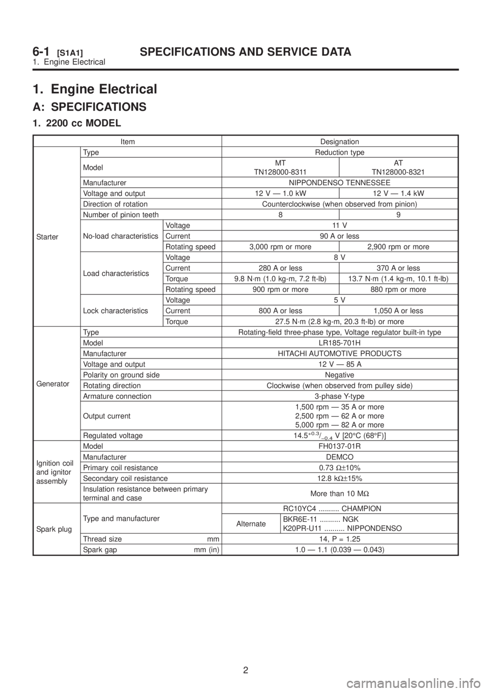
1. Engine Electrical
A: SPECIFICATIONS
1. 2200 cc MODEL
Item Designation
StarterType Reduction type
ModelMT
TN128000-8311AT
TN128000-8321
Manufacturer NIPPONDENSO TENNESSEE
Voltage and output 12 V Ð 1.0 kW 12 V Ð 1.4 kW
Direction of rotation Counterclockwise (when observed from pinion)
Number of pinion teeth 8 9
No-load characteristicsVoltage 11 V
Current 90 A or less
Rotating speed 3,000 rpm or more 2,900 rpm or more
Load characteristicsVoltage 8 V
Current 280 A or less 370 A or less
Torque 9.8 N´m (1.0 kg-m, 7.2 ft-lb) 13.7 N´m (1.4 kg-m, 10.1 ft-lb)
Rotating speed 900 rpm or more 880 rpm or more
Lock characteristicsVoltage 5 V
Current 800 A or less 1,050 A or less
Torque 27.5 N´m (2.8 kg-m, 20.3 ft-lb) or more
GeneratorType Rotating-field three-phase type, Voltage regulator built-in type
Model LR185-701H
Manufacturer HITACHI AUTOMOTIVE PRODUCTS
Voltage and output 12VÐ85A
Polarity on ground side Negative
Rotating direction Clockwise (when observed from pulley side)
Armature connection 3-phase Y-type
Output current1,500 rpm Ð 35 A or more
2,500 rpm Ð 62 A or more
5,000 rpm Ð 82 A or more
Regulated voltage 14.5
+0.3/þ0.4V [20ÉC (68ÉF)]
Ignition coil
and ignitor
assemblyModel FH0137-01R
Manufacturer DEMCO
Primary coil resistance 0.73W±10%
Secondary coil resistance 12.8 kW±15%
Insulation resistance between primary
terminal and caseMore than 10 MW
Spark plugType and manufacturerRC10YC4 .......... CHAMPION
AlternateBKR6E-11 .......... NGK
K20PR-U11 .......... NIPPONDENSO
Thread size mm 14, P = 1.25
Spark gap mm (in) 1.0 Ð 1.1 (0.039 Ð 0.043)
2
6-1[S1A1]SPECIFICATIONS AND SERVICE DATA
1. Engine Electrical
Page 1184 of 1456
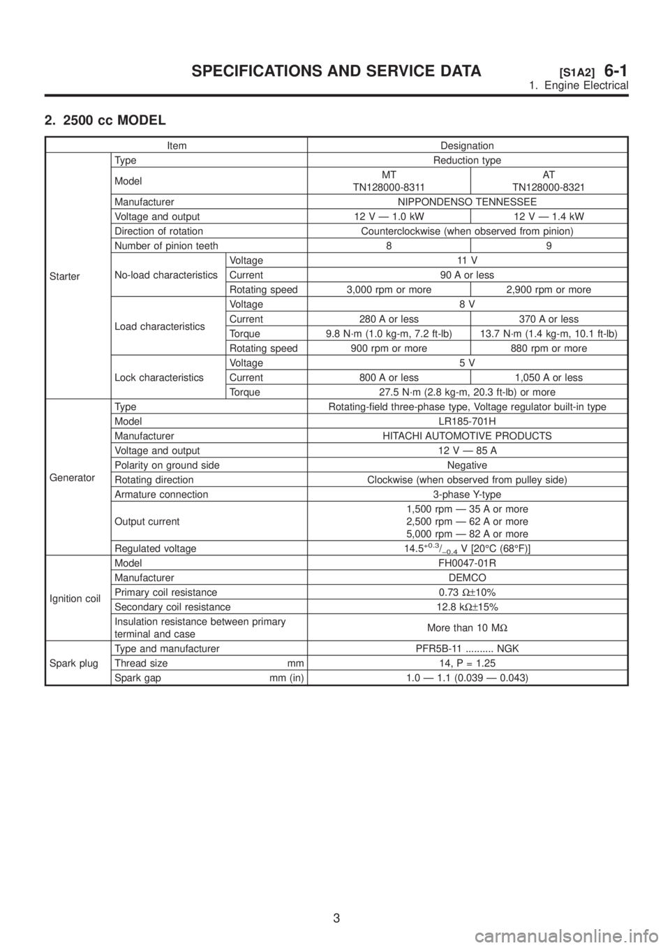
2. 2500 cc MODEL
Item Designation
StarterType Reduction type
ModelMT
TN128000-8311AT
TN128000-8321
Manufacturer NIPPONDENSO TENNESSEE
Voltage and output 12 V Ð 1.0 kW 12 V Ð 1.4 kW
Direction of rotation Counterclockwise (when observed from pinion)
Number of pinion teeth 8 9
No-load characteristicsVoltage 11 V
Current 90 A or less
Rotating speed 3,000 rpm or more 2,900 rpm or more
Load characteristicsVoltage 8 V
Current 280 A or less 370 A or less
Torque 9.8 N´m (1.0 kg-m, 7.2 ft-lb) 13.7 N´m (1.4 kg-m, 10.1 ft-lb)
Rotating speed 900 rpm or more 880 rpm or more
Lock characteristicsVoltage 5 V
Current 800 A or less 1,050 A or less
Torque 27.5 N´m (2.8 kg-m, 20.3 ft-lb) or more
GeneratorType Rotating-field three-phase type, Voltage regulator built-in type
Model LR185-701H
Manufacturer HITACHI AUTOMOTIVE PRODUCTS
Voltage and output 12VÐ85A
Polarity on ground side Negative
Rotating direction Clockwise (when observed from pulley side)
Armature connection 3-phase Y-type
Output current1,500 rpm Ð 35 A or more
2,500 rpm Ð 62 A or more
5,000 rpm Ð 82 A or more
Regulated voltage 14.5
+0.3/þ0.4V [20ÉC (68ÉF)]
Ignition coilModel FH0047-01R
Manufacturer DEMCO
Primary coil resistance 0.73W±10%
Secondary coil resistance 12.8 kW±15%
Insulation resistance between primary
terminal and caseMore than 10 MW
Spark plugType and manufacturer PFR5B-11 .......... NGK
Thread size mm 14, P = 1.25
Spark gap mm (in) 1.0 Ð 1.1 (0.039 Ð 0.043)
3
[S1A2]6-1SPECIFICATIONS AND SERVICE DATA
1. Engine Electrical
Page 1227 of 1456
1. Precaution
IBefore disassembling or reassembling parts,
always disconnect battery ground cable. When
repairing radio, control modules, etc. which are
provided with memory functions, record
memory contents before disconnecting battery
ground cable. Otherwise, these contents are
cancelled upon disconnection.
IReassemble parts in reverse order of disas-
sembly procedure unless otherwise indicated.
IAdjust parts to specifications contained in
this manual if so designated.
IConnect connectors and hoses securely dur-
ing reassembly.
IAfter reassembly, ensure functional parts
operate smoothly.
CAUTION:
IAirbag system wiring harness is routed near
the electrical parts and switch.
IAll Airbag system wiring harness and con-
nectors are colored yellow. Do not use electri-
cal test equipment on these circuits.
IBe careful not to damage Airbag system wir-
ing harness when servicing the ignition key
cylinder.
2. Battery
A: REMOVAL AND INSTALLATION
1. BATTERY
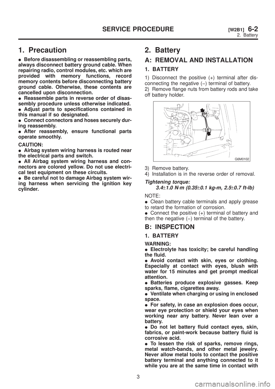
1) Disconnect the positive (+) terminal after dis-
connecting the negative (þ) terminal of battery.
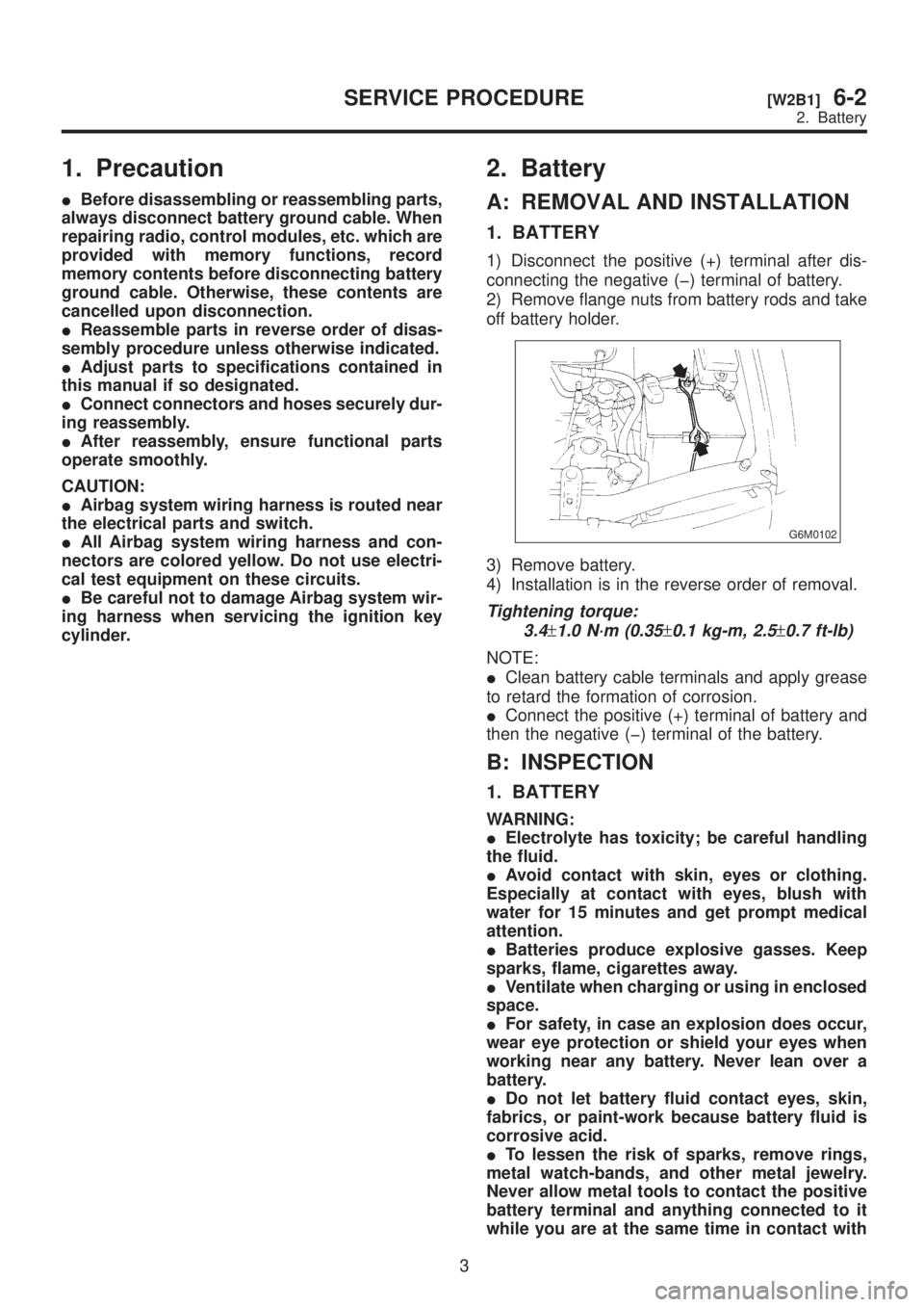
2) Remove flange nuts from battery rods and take
off battery holder.
G6M0102
3) Remove battery.
4) Installation is in the reverse order of removal.
Tightening torque:
3.4
±1.0 N´m (0.35±0.1 kg-m, 2.5±0.7 ft-lb)
NOTE:
IClean battery cable terminals and apply grease
to retard the formation of corrosion.
IConnect the positive (+) terminal of battery and
then the negative (þ) terminal of the battery.
B: INSPECTION
1. BATTERY
WARNING:
IElectrolyte has toxicity; be careful handling
the fluid.
IAvoid contact with skin, eyes or clothing.
Especially at contact with eyes, blush with
water for 15 minutes and get prompt medical
attention.
IBatteries produce explosive gasses. Keep
sparks, flame, cigarettes away.
IVentilate when charging or using in enclosed
space.
IFor safety, in case an explosion does occur,
wear eye protection or shield your eyes when
working near any battery. Never lean over a
battery.
IDo not let battery fluid contact eyes, skin,
fabrics, or paint-work because battery fluid is
corrosive acid.
ITo lessen the risk of sparks, remove rings,
metal watch-bands, and other metal jewelry.
Never allow metal tools to contact the positive
battery terminal and anything connected to it
while you are at the same time in contact with
3
[W2B1]6-2SERVICE PROCEDURE
2. Battery
Page 1228 of 1456
1. Precaution
IBefore disassembling or reassembling parts,
always disconnect battery ground cable. When
repairing radio, control modules, etc. which are
provided with memory functions, record
memory contents before disconnecting battery
ground cable. Otherwise, these contents are
cancelled upon disconnection.
IReassemble parts in reverse order of disas-
sembly procedure unless otherwise indicated.
IAdjust parts to specifications contained in
this manual if so designated.
IConnect connectors and hoses securely dur-
ing reassembly.
IAfter reassembly, ensure functional parts
operate smoothly.
CAUTION:
IAirbag system wiring harness is routed near
the electrical parts and switch.
IAll Airbag system wiring harness and con-
nectors are colored yellow. Do not use electri-
cal test equipment on these circuits.
IBe careful not to damage Airbag system wir-
ing harness when servicing the ignition key
cylinder.
2. Battery
A: REMOVAL AND INSTALLATION
1. BATTERY
1) Disconnect the positive (+) terminal after dis-
connecting the negative (þ) terminal of battery.
2) Remove flange nuts from battery rods and take
off battery holder.
G6M0102
3) Remove battery.
4) Installation is in the reverse order of removal.
Tightening torque:
3.4
±1.0 N´m (0.35±0.1 kg-m, 2.5±0.7 ft-lb)
NOTE:
IClean battery cable terminals and apply grease
to retard the formation of corrosion.
IConnect the positive (+) terminal of battery and
then the negative (þ) terminal of the battery.
B: INSPECTION
1. BATTERY
WARNING:
IElectrolyte has toxicity; be careful handling
the fluid.
IAvoid contact with skin, eyes or clothing.
Especially at contact with eyes, blush with
water for 15 minutes and get prompt medical
attention.
IBatteries produce explosive gasses. Keep
sparks, flame, cigarettes away.
IVentilate when charging or using in enclosed
space.
IFor safety, in case an explosion does occur,
wear eye protection or shield your eyes when
working near any battery. Never lean over a
battery.
IDo not let battery fluid contact eyes, skin,
fabrics, or paint-work because battery fluid is
corrosive acid.
ITo lessen the risk of sparks, remove rings,
metal watch-bands, and other metal jewelry.
Never allow metal tools to contact the positive
battery terminal and anything connected to it
while you are at the same time in contact with
3
[W2B1]6-2SERVICE PROCEDURE
2. Battery