1999 SUBARU LEGACY torque specifications
[x] Cancel search: torque specificationsPage 72 of 1456

IPress-in the push adjuster rod gradually tak-
ing more than three minutes.
IDo not allow press pressure to exceed 9,807
N (1,000 kg, 2,205 lb).
IPress the adjuster rod as far as the end sur-
face of the cylinder. Do not press the adjuster
rod into the cylinder. Doing so may damage the
cylinder.
4) Measure the extension of rod beyond the body.
If it is not within specifications, replace with a new
one.
Rod extension: H
5.7
±0.5 mm (0.224±0.020 in)
H2M2381A
3. BELT TENSION PULLEY
1) Check mating surfaces of timing belt and con-
tact point of adjuster rod for abnormal wear or
scratches. Replace automatic belt tension adjuster
assembly if faulty.
2) Check tension pulley for smooth rotation.
Replace if noise or excessive play is noted.
3) Check tension pulley for grease leakage.
4. BELT IDLER
1) Check belt idler for smooth rotation. Replace if
noise or excessive play is noted.
2) Check belt outer contacting surfaces of idler
pulley for abnormal wear and scratches.
3) Check belt idler for grease leakage.
5. CAMSHAFT AND CRANKSHAFT
SPROCKET
1) Check sprocket teeth for abnormal wear and
scratches.
2) Make sure there is no free play between
sprocket and key.
3) Check crankshaft sprocket notch for sensor for
damage and contamination of foreign matter.
C: INSTALLATION
1. CAMSHAFT AND CRANKSHAFT SPROCKET
B2M2598A
(1) Tensioner bracket
(2) Belt cover No. 2 (RH)
(3) Belt cover No. 2 (LH)
(4) Crankshaft sprocket(5) Camshaft sprocket No. 1
(6) Camshaft sprocket No. 2Tightening torque: N´m (kg-m, ft-lb)
T1:
5±1 (0.5±0.1, 3.6±0.7)
T2:25±3 (2.5±0.3, 18.1±2.2)
T3:78±5 (8.0±0.5, 57.9±3.6)
19
[W2C1]2-3aSERVICE PROCEDURE
2. Timing Belt
Page 468 of 1456

4. Drive Pinion Assembly
Preload adjustment of thrust bearing
Starting torque
0.3 Ð 0.8 N´m (3 Ð 8 kg-m, 2.6 Ð 6.9 in-lb)
Adjusting washer No. 1
Part No. Thickness mm (in)
803025051 3.925 (0.1545)
803025052 3.950 (0.1555)
803025053 3.975 (0.1565)
803025054 4.000 (0.1575)
803025055 4.025 (0.1585)
803025056 4.050 (0.1594)
803025057 4.075 (0.1604)
Adjusting washer No. 2
Part No. Thickness mm (in)
803025059 3.850 (0.1516)
803025054 4.000 (0.1575)
803025058 4.150 (0.1634)
Assemble a driven shaft and 1st driven gear that
are selected for the proper radial clearance adjust-
ment
Driven shaft 1st driven gear
Part No.Diameter A
mm (in)Part No.
32229AA15049.959 Ð 49.966
(1.9669 Ð 1.9672)32231AA730
32229AA14049.967 Ð 49.975
(1.9672 Ð 1.9675)32231AA720
5. Reverse Idler Gear
Adjustment of reverse idler gear position
Reverse idler gear to transmission case (LH) wall
clearance
6.0 Ð 7.5 mm (0.236 Ð 0.295 in)
Reverse shifter lever
Part No. Mark Remarks
32820AA070 7Further from case
wall
32820AA080 8 Standard
32820AA090 9Closer to the case
wall
After installing a suitable reverse shifter lever,
adjust reverse idler gear to transmission case wall
clearance to within 0 to 0.5 mm (0 to 0.020 in)
using washers.
Washer (20.5´26´t)
Part No.Thickness
mm (in)Part No.Thickness
mm (in)
803020151 0.4 (0.016) 803020154 1.9 (0.075)
803020152 1.1 (0.043) 803020155 2.3 (0.091)
803020153 1.5 (0.059) Ð Ð
3
[S500]3-1SPECIFICATIONS AND SERVICE DATA
5. Reverse Idler Gear
Page 469 of 1456
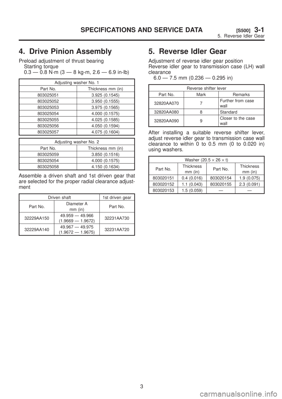
4. Drive Pinion Assembly
Preload adjustment of thrust bearing
Starting torque
0.3 Ð 0.8 N´m (3 Ð 8 kg-m, 2.6 Ð 6.9 in-lb)
Adjusting washer No. 1
Part No. Thickness mm (in)
803025051 3.925 (0.1545)
803025052 3.950 (0.1555)
803025053 3.975 (0.1565)
803025054 4.000 (0.1575)
803025055 4.025 (0.1585)
803025056 4.050 (0.1594)
803025057 4.075 (0.1604)
Adjusting washer No. 2
Part No. Thickness mm (in)
803025059 3.850 (0.1516)
803025054 4.000 (0.1575)
803025058 4.150 (0.1634)
Assemble a driven shaft and 1st driven gear that
are selected for the proper radial clearance adjust-
ment
Driven shaft 1st driven gear
Part No.Diameter A
mm (in)Part No.
32229AA15049.959 Ð 49.966
(1.9669 Ð 1.9672)32231AA730
32229AA14049.967 Ð 49.975
(1.9672 Ð 1.9675)32231AA720
5. Reverse Idler Gear
Adjustment of reverse idler gear position
Reverse idler gear to transmission case (LH) wall
clearance
6.0 Ð 7.5 mm (0.236 Ð 0.295 in)
Reverse shifter lever
Part No. Mark Remarks
32820AA070 7Further from case
wall
32820AA080 8 Standard
32820AA090 9Closer to the case
wall
After installing a suitable reverse shifter lever,
adjust reverse idler gear to transmission case wall
clearance to within 0 to 0.5 mm (0 to 0.020 in)
using washers.
Washer (20.5´26´t)
Part No.Thickness
mm (in)Part No.Thickness
mm (in)
803020151 0.4 (0.016) 803020154 1.9 (0.075)
803020152 1.1 (0.043) 803020155 2.3 (0.091)
803020153 1.5 (0.059) Ð Ð
3
[S500]3-1SPECIFICATIONS AND SERVICE DATA
5. Reverse Idler Gear
Page 493 of 1456
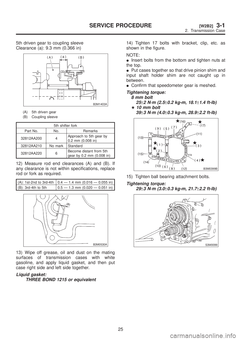
5th driven gear to coupling sleeve
Clearance (a): 9.3 mm (0.366 in)
B3M1403A
(A) 5th driven gear
(B) Coupling sleeve
5th shifter fork
Part No. No. Remarks
32812AA200 4Approach to 5th gear by
0.2 mm (0.008 in)
32812AA210 No mark Standard
32812AA220 6Become distant from 5th
gear by 0.2 mm (0.008 in)
12) Measure rod end clearances (A) and (B). If
any clearance is not within specifications, replace
rod or fork as required.
(A): 1st-2nd to 3rd-4th 0.4 Ð 1.4 mm (0.016 Ð 0.055 in)
(B): 3rd-4th to 5th 0.5 Ð 1.3 mm (0.020 Ð 0.051 in)
B3M0530A
13) Wipe off grease, oil and dust on the mating
surfaces of transmission cases with white
gasoline, and apply liquid gasket, and then put
case right side and left side together.
Liquid gasket:
THREE BOND 1215 or equivalent
14) Tighten 17 bolts with bracket, clip, etc. as
shown in the figure.
NOTE:
IInsert bolts from the bottom and tighten nuts at
the top.
IPut cases together so that drive pinion shim and
input shaft holder shim are not caught up in
between.
IConfirm that speedometer gear is meshed.
Tightening torque:
8 mm bolt
25
±2 N´m (2.5±0.2 kg-m, 18.1±1.4 ft-lb)
H10 mm bolt
39
±3 N´m (4.0±0.3 kg-m, 28.9±2.2 ft-lb)
B3M0399B
15) Tighten ball bearing attachment bolts.
Tightening torque:
29
±3 N´m (3.0±0.3 kg-m, 21.7±2.2 ft-lb)
S3M0099
25
[W2B2]3-1SERVICE PROCEDURE
2. Transmission Case
Page 521 of 1456

2) Measure backlash between bevel gear and pin-
ion. If it is not within specifications, install a suitable
washer to adjust it.
NOTE:
Be sure the pinion gear tooth contacts adjacent
gear teeth during measurement.
ST1 498247001 MAGNET BASE
ST2 498247100 DIAL GAUGE
Standard backlash:
0.13 Ð 0.18 mm (0.0051 Ð 0.0071 in)
G3M0670
Washer (38.1´50´t)
Part No. Thickness mm (in)
8030380210.925 Ð 0.950
(0.0364 Ð 0.0374)
8030380220.975 Ð 1.000
(0.0384 Ð 0.0394)
8030380231.025 Ð 1.050
(0.0404 Ð 0.0413)
3) Align pinion shaft and differential case at their
holes, and drive straight pin into holes from the
hypoid driven gear side, using ST.
NOTE:
Lock straight pin after installing.
ST 899904100 REMOVER
B3M0609C
(A) Pinion shaft
(B) Differential case
(C) Straight pin
4) Install roller bearing (40´80´19.75) to differ-
ential case.
NOTE:
Be careful because roller bearing outer races are
used as a set.
ST1 499277100 BUSH 1-2 INSTALLER
ST2 398497701 ADAPTER
G3M0671
5) Install hypoid driven gear to differential case
using twelve bolts.
Tightening torque:
T: 6 2
±5 N´m (6.3±0.5 kg-m, 45.6±3.6 ft-lb)
B3M0554C
(A) Hypoid driven gear
(B) Differential case
50
3-1[W6B0]SERVICE PROCEDURE
6. Front Differential
Page 527 of 1456
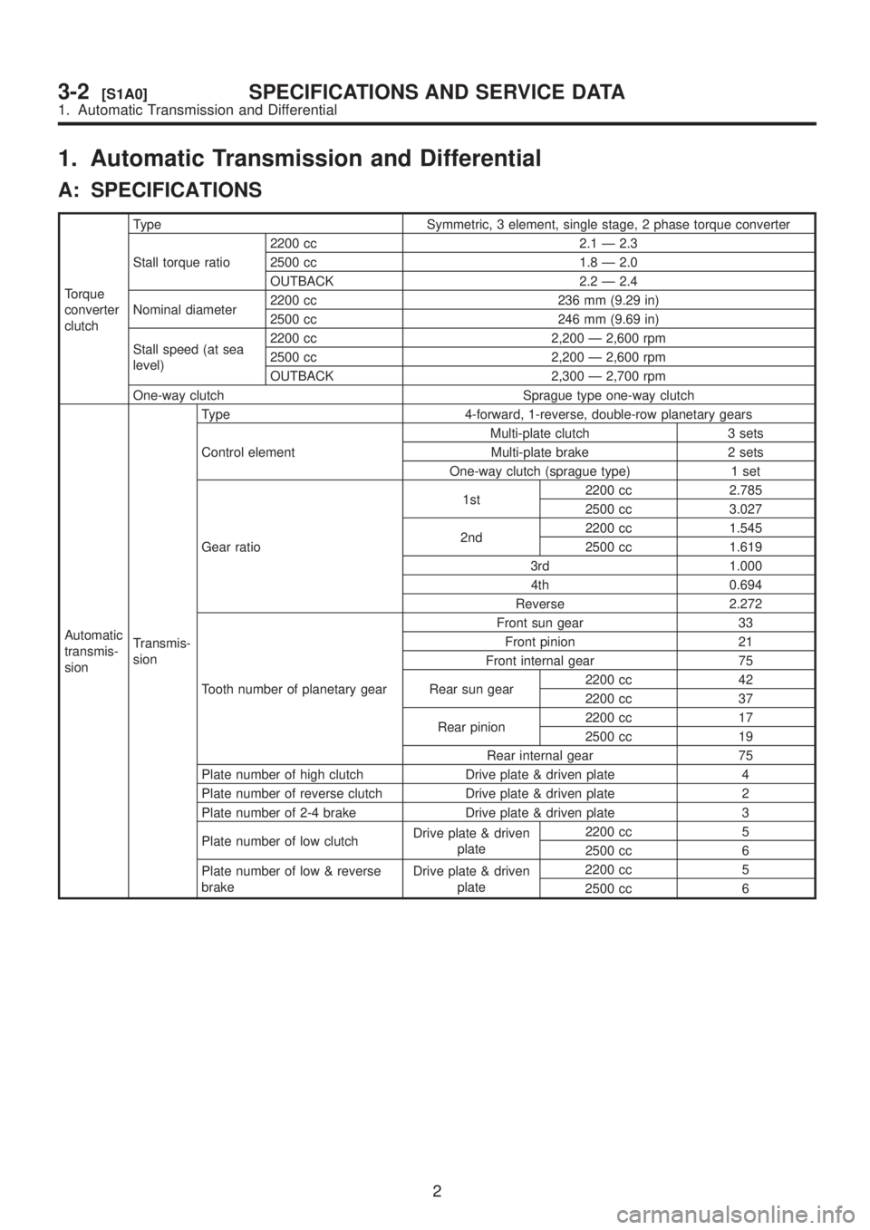
1. Automatic Transmission and Differential
A: SPECIFICATIONS
Torque
converter
clutchType Symmetric, 3 element, single stage, 2 phase torque converter
Stall torque ratio2200 cc 2.1 Ð 2.3
2500 cc 1.8 Ð 2.0
OUTBACK 2.2 Ð 2.4
Nominal diameter2200 cc 236 mm (9.29 in)
2500 cc 246 mm (9.69 in)
Stall speed (at sea
level)2200 cc 2,200 Ð 2,600 rpm
2500 cc 2,200 Ð 2,600 rpm
OUTBACK 2,300 Ð 2,700 rpm
One-way clutch Sprague type one-way clutch
Automatic
transmis-
sionTransmis-
sionType 4-forward, 1-reverse, double-row planetary gears
Control elementMulti-plate clutch 3 sets
Multi-plate brake 2 sets
One-way clutch (sprague type) 1 set
Gear ratio1st2200 cc 2.785
2500 cc 3.027
2nd2200 cc 1.545
2500 cc 1.619
3rd 1.000
4th 0.694
Reverse 2.272
Tooth number of planetary gearFront sun gear 33
Front pinion 21
Front internal gear 75
Rear sun gear2200 cc 42
2200 cc 37
Rear pinion2200 cc 17
2500 cc 19
Rear internal gear 75
Plate number of high clutch Drive plate & driven plate 4
Plate number of reverse clutch Drive plate & driven plate 2
Plate number of 2-4 brake Drive plate & driven plate 3
Plate number of low clutchDrive plate & driven
plate2200 cc 5
2500 cc 6
Plate number of low & reverse
brakeDrive plate & driven
plate2200 cc 5
2500 cc 6
2
3-2[S1A0]SPECIFICATIONS AND SERVICE DATA
1. Automatic Transmission and Differential
Page 570 of 1456
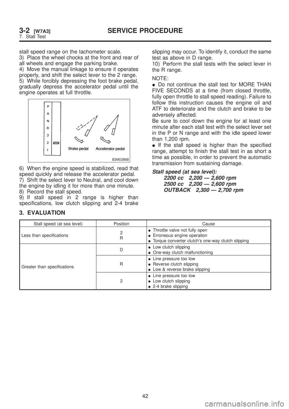
stall speed range on the tachometer scale.
3) Place the wheel chocks at the front and rear of
all wheels and engage the parking brake.
4) Move the manual linkage to ensure it operates
properly, and shift the select lever to the 2 range.
5) While forcibly depressing the foot brake pedal,
gradually depress the accelerator pedal until the
engine operates at full throttle.
B3M0286B
6) When the engine speed is stabilized, read that
speed quickly and release the accelerator pedal.
7) Shift the select lever to Neutral, and cool down
the engine by idling it for more than one minute.
8) Record the stall speed.
9) If stall speed in 2 range is higher than
specifications, low clutch slipping and 2-4 brakeslipping may occur. To identify it, conduct the same
test as above in D range.
10) Perform the stall tests with the select lever in
the R range.
NOTE:
IDo not continue the stall test for MORE THAN
FIVE SECONDS at a time (from closed throttle,
fully open throttle to stall speed reading). Failure to
follow this instruction causes the engine oil and
ATF to deteriorate and the clutch and brake to be
adversely affected.
Be sure to cool down the engine for at least one
minute after each stall test with the select lever set
in the P or N range and with the idle speed lower
than 1,200 rpm.
IIf the stall speed is higher than the specified
range, attempt to finish the stall test in as short a
time as possible, in order to prevent the automatic
transmission from sustaining damage.Stall speed (at sea level):
2200 cc 2,200 Ð 2,600 rpm
2500 cc 2,200 Ð 2,600 rpm
OUTBACK 2,300 Ð 2,700 rpm
3. EVALUATION
Stall speed (at sea level) Position Cause
Less than specifications2
RIThrottle valve not fully open
IErroneous engine operation
ITorque converter clutch's one-way clutch slipping
Greater than specificationsDILow clutch slipping
IOne-way clutch malfunctioning
RILine pressure too low
IReverse clutch slipping
ILow & reverse brake slipping
2ILine pressure too low
ILow clutch slipping
I2-4 brake slipping
42
3-2[W7A3]SERVICE PROCEDURE
7. Stall Test
Page 600 of 1456
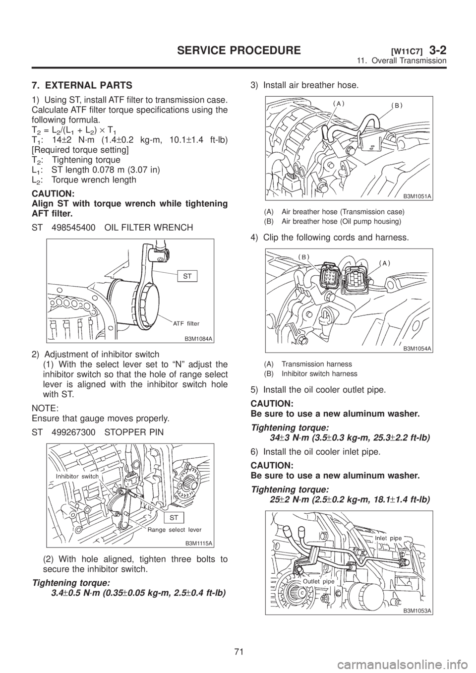
7. EXTERNAL PARTS
1) Using ST, install ATF filter to transmission case.
Calculate ATF filter torque specifications using the
following formula.
T
2=L2/(L1+L2)´T1T1:14±2 N´m (1.4±0.2 kg-m, 10.1±1.4 ft-lb)
[Required torque setting]
T
2: Tightening torque
L
1: ST length 0.078 m (3.07 in)
L
2: Torque wrench length
CAUTION:
Align ST with torque wrench while tightening
AFT filter.
ST 498545400 OIL FILTER WRENCH
B3M1084A
2) Adjustment of inhibitor switch
(1) With the select lever set to ªNº adjust the
inhibitor switch so that the hole of range select
lever is aligned with the inhibitor switch hole
with ST.
NOTE:
Ensure that gauge moves properly.
ST 499267300 STOPPER PIN
B3M1115A
(2) With hole aligned, tighten three bolts to
secure the inhibitor switch.
Tightening torque:
3.4
±0.5 N´m (0.35±0.05 kg-m, 2.5±0.4 ft-lb)
3) Install air breather hose.
B3M1051A
(A) Air breather hose (Transmission case)
(B) Air breather hose (Oil pump housing)
4) Clip the following cords and harness.
B3M1054A
(A) Transmission harness
(B) Inhibitor switch harness
5) Install the oil cooler outlet pipe.
CAUTION:
Be sure to use a new aluminum washer.
Tightening torque:
34
±3 N´m (3.5±0.3 kg-m, 25.3±2.2 ft-lb)
6) Install the oil cooler inlet pipe.
CAUTION:
Be sure to use a new aluminum washer.
Tightening torque:
25
±2 N´m (2.5±0.2 kg-m, 18.1±1.4 ft-lb)
B3M1053A
71
[W11C7]3-2SERVICE PROCEDURE
11. Overall Transmission