1999 SUBARU LEGACY torque specifications
[x] Cancel search: torque specificationsPage 605 of 1456

14. Control Valve Body
A: PRECAUTION
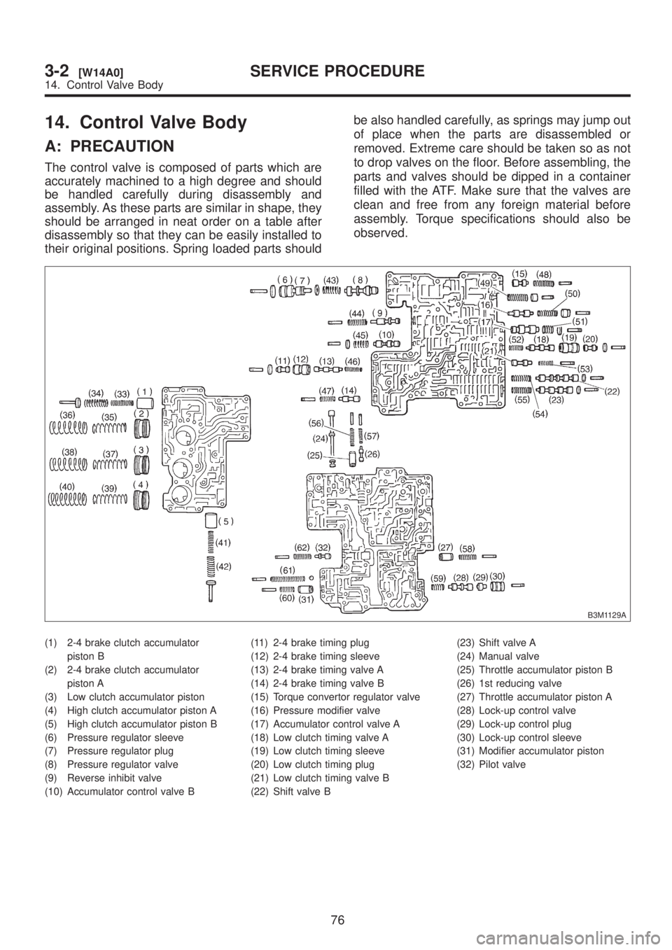
The control valve is composed of parts which are
accurately machined to a high degree and should
be handled carefully during disassembly and
assembly. As these parts are similar in shape, they
should be arranged in neat order on a table after
disassembly so that they can be easily installed to
their original positions. Spring loaded parts shouldbe also handled carefully, as springs may jump out
of place when the parts are disassembled or
removed. Extreme care should be taken so as not
to drop valves on the floor. Before assembling, the
parts and valves should be dipped in a container
filled with the ATF. Make sure that the valves are
clean and free from any foreign material before
assembly. Torque specifications should also be
observed.
B3M1129A
(1) 2-4 brake clutch accumulator
piston B
(2) 2-4 brake clutch accumulator
piston A
(3) Low clutch accumulator piston
(4) High clutch accumulator piston A
(5) High clutch accumulator piston B
(6) Pressure regulator sleeve
(7) Pressure regulator plug
(8) Pressure regulator valve
(9) Reverse inhibit valve
(10) Accumulator control valve B(11) 2-4 brake timing plug
(12) 2-4 brake timing sleeve
(13) 2-4 brake timing valve A
(14) 2-4 brake timing valve B
(15) Torque convertor regulator valve
(16) Pressure modifier valve
(17) Accumulator control valve A
(18) Low clutch timing valve A
(19) Low clutch timing sleeve
(20) Low clutch timing plug
(21) Low clutch timing valve B
(22) Shift valve B(23) Shift valve A
(24) Manual valve
(25) Throttle accumulator piston B
(26) 1st reducing valve
(27) Throttle accumulator piston A
(28) Lock-up control valve
(29) Lock-up control plug
(30) Lock-up control sleeve
(31) Modifier accumulator piston
(32) Pilot valve
76
3-2[W14A0]SERVICE PROCEDURE
14. Control Valve Body
Page 611 of 1456

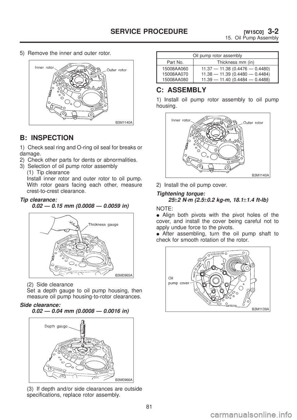
5) Remove the inner and outer rotor.
B3M1140A
B: INSPECTION
1) Check seal ring and O-ring oil seal for breaks or
damage.
2) Check other parts for dents or abnormalities.
3) Selection of oil pump rotor assembly
(1) Tip clearance
Install inner rotor and outer rotor to oil pump.
With rotor gears facing each other, measure
crest-to-crest clearance.
Tip clearance:
0.02 Ð 0.15 mm (0.0008 Ð 0.0059 in)
B3M0965A
(2) Side clearance
Set a depth gauge to oil pump housing, then
measure oil pump housing-to-rotor clearances.
Side clearance:
0.02 Ð 0.04 mm (0.0008 Ð 0.0016 in)
B3M0966A
(3) If depth and/or side clearances are outside
specifications, replace rotor assembly.
Oil pump rotor assembly
Part No. Thickness mm (in)
15008AA060
15008AA070
15008AA08011.37 Ð 11.38 (0.4476 Ð 0.4480)
11.38 Ð 11.39 (0.4480 Ð 0.4484)
11.39 Ð 11.40 (0.4484 Ð 0.4488)
C: ASSEMBLY
1) Install oil pump rotor assembly to oil pump
housing.
B3M1140A
2) Install the oil pump cover.
Tightening torque:
25
±2 N´m (2.5±0.2 kg-m, 18.1±1.4 ft-lb)
NOTE:
IAlign both pivots with the pivot holes of the
cover, and install the cover being careful not to
apply undue force to the pivots.
IAfter assembling, turn the oil pump shaft to
check for smooth rotation of the rotor.
B3M1139A
81
[W15C0]3-2SERVICE PROCEDURE
15. Oil Pump Assembly
Page 711 of 1456

2. CAMBER (FRONT AND REAR)
IInspection
1) Place front wheel on turning radius gauge.
Make sure ground contacting surfaces of front and
rear wheels are set at the same height.
2) Set ST into the center of the wheel, and then
install the wheel alignment gauge.
ST 927380000 ADAPTER
B4M0567A
NOTE:
Refer to the ªSPECIFICATIONS AND SERVICE
DATAº for the camber values.
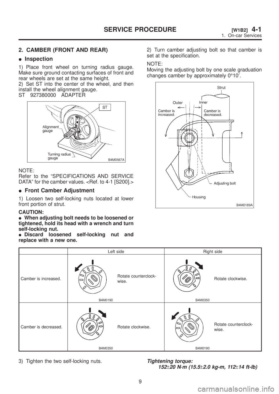
IFront Camber Adjustment
1) Loosen two self-locking nuts located at lower
front portion of strut.
CAUTION:
IWhen adjusting bolt needs to be loosened or
tightened, hold its head with a wrench and turn
self-locking nut.
IDiscard loosened self-locking nut and
replace with a new one.2) Turn camber adjusting bolt so that camber is
set at the specification.
NOTE:
Moving the adjusting bolt by one scale graduation
changes camber by approximately 0É10¢.
B4M0189A
Left side Right side
Camber is increased.
B4M0190
Rotate counterclock-
wise.
B4M0350
Rotate clockwise.
Camber is decreased.
B4M0350
Rotate clockwise.
B4M0190
Rotate counterclock-
wise.
3) Tighten the two self-locking nuts.Tightening torque:
152
±20 N´m (15.5±2.0 kg-m, 112±14 ft-lb)
9
[W1B2]4-1SERVICE PROCEDURE
1. On-car Services
Page 712 of 1456

3. CASTER (FRONT)
IInspection
1) Place front wheel on turning radius gauge.
Make sure ground contacting surfaces of front and
rear wheels are set at the same height.
2) Set ST into the center of the wheel, and then
install the wheel alignment gauge.
ST 927380000 ADAPTER
B4M0567A
NOTE:
Refer to the ªSPECIFICATIONS AND SERVICE
DATAº for the caster value.
4. FRONT WHEEL TOE-IN
IInspection
1) Using a toe gauge, measure front wheel toe-in.
Toe-in:
0
±3mm(±0.12 in)
2) Mark rear sides of left and right tires at height
corresponding to center of spindles and measure
distance ªBº between marks.
3) Move vehicle forward so that marks line up with
front sides at height corresponding to center of
spindles.
4) Measure distance ªAº between left and right
marks. Toe-in can then be obtained by the follow-
ing equation:
B þ A = Toe-in
H4M1279
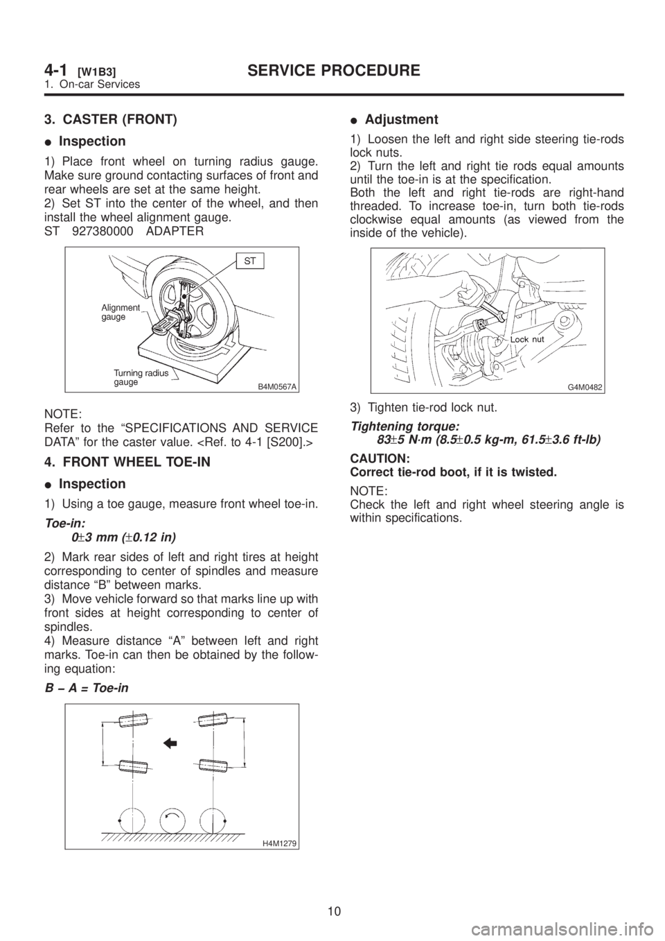
IAdjustment
1) Loosen the left and right side steering tie-rods
lock nuts.
2) Turn the left and right tie rods equal amounts
until the toe-in is at the specification.
Both the left and right tie-rods are right-hand
threaded. To increase toe-in, turn both tie-rods
clockwise equal amounts (as viewed from the
inside of the vehicle).
G4M0482
3) Tighten tie-rod lock nut.
Tightening torque:
83
±5 N´m (8.5±0.5 kg-m, 61.5±3.6 ft-lb)
CAUTION:
Correct tie-rod boot, if it is twisted.
NOTE:
Check the left and right wheel steering angle is
within specifications.
10
4-1[W1B3]SERVICE PROCEDURE
1. On-car Services
Page 931 of 1456

4) Install front ABS sensor on strut and wheel
apron bracket.
Tightening torque:
32
±10 N´m (3.3±1.0 kg-m, 24±7 ft-lb)
B4M1181A
5) Place a thickness gauge between ABS sensor's
pole piece and tone wheel's tooth face. After stan-
dard clearance is obtained over the entire
perimeter, tighten ABS sensor on housing to speci-
fied torque.
ABS sensor standard clearance:
0.9 Ð 1.4 mm (0.035 Ð 0.055 in)
Tightening torque:
32
±10 N´m (3.3±1.0 kg-m, 24±7 ft-lb)
CAUTION:
Check the marks on the harness to make sure
that no distortion exists. (RH: white, LH: yel-
low)
NOTE:
If the clearance is outside specifications, readjust.
2. REAR ABS SENSOR
1) Install rear tone wheel on hub, then rear hous-
ing on hub.
2) Temporarily install rear ABS sensor on back
plate.
CAUTION:
Be careful not to strike ABS sensor's pole
piece and tone wheel's teeth against adjacent
metal parts during installation.
B4M1182A
3) Install rear drive shaft to rear housing and rear
differential spindle.
Tightening torque:
32
±10 N´m (3.3±1.0 kg-m, 24±7 ft-lb)
G4M0453
5) Place a thickness gauge between ABS sensor's
pole piece and tone wheel's tooth face. After stan-
dard clearance is obtained over the entire
perimeter, tighten ABS sensor on back plate to
specified torque.
ABS sensor standard clearance:
0.7 Ð 1.2 mm (0.028 Ð 0.047 in)
Tightening torque:
32
±10 N´m (3.3±1.0 kg-m, 24±7 ft-lb)
CAUTION:
Check the marks on the harness to make sure
that no distortion exists. (RH: white, LH: yel-
low)
NOTE:
If the clearance is outside specifications, readjust.
54
4-4[W14C2]SERVICE PROCEDURE
14. ABS Sensor
Page 937 of 1456

E: INSTALLATION
1) Install ABSCM&H/U.
CAUTION:
Confirm that the specifications of the
ABSCM&H/U conforms to the vehicle specifica-
tions.
Tightening torque:
18
±5 N´m (1.8±0.5 kg-m, 13.0±3.6 ft-lb)
B4M1222
2) Connect brake pipes to their correct
ABSCM&H/U connections.
Brake pipe tightening torque:
15+3/þ2N´m (1.5+0.3/þ0.2kg-m, 10.8+2.2/þ1.4ft-lb)
3) Using cable clip, secure ABSCM&H/U harness
to bracket.
4) Connect connector to ABSCM&H/U.
CAUTION:
IBe sure to remove all foreign matter from
inside the connector before connecting.
IEnsure that the ABSCM&H/U connetor is
securely locked.
5) Install air intake duct.
6) Connect ground cable to battery.
7) Bleed air from the brake system.
16. G Sensor
A: REMOVAL
1. FRONT ABS SENSOR
1) Disconnect front ABS sensor connector located
in engine compartment.
2) Remove bolts which secure sensor harness to
strut.
B4M1442A
3) Remove bolts which secure sensor harness to
body.
B4M1181A
4) Remove bolts which secure front ABS sensor to
housing, and remove front ABS sensor.
CAUTION:
IBe careful not to damage pole piece located
at tip of the sensor and teeth faces during
removal.
IDo not pull sensor harness during removal.
B4M1183A
5) Remove front disc brake caliper and disc rotor
from housing after removing front tire.
60
4-4[W15E0]SERVICE PROCEDURE
16. G Sensor
Page 938 of 1456

E: INSTALLATION
1) Install ABSCM&H/U.
CAUTION:
Confirm that the specifications of the
ABSCM&H/U conforms to the vehicle specifica-
tions.
Tightening torque:
18
±5 N´m (1.8±0.5 kg-m, 13.0±3.6 ft-lb)
B4M1222
2) Connect brake pipes to their correct
ABSCM&H/U connections.
Brake pipe tightening torque:
15+3/þ2N´m (1.5+0.3/þ0.2kg-m, 10.8+2.2/þ1.4ft-lb)
3) Using cable clip, secure ABSCM&H/U harness
to bracket.
4) Connect connector to ABSCM&H/U.
CAUTION:
IBe sure to remove all foreign matter from
inside the connector before connecting.
IEnsure that the ABSCM&H/U connetor is
securely locked.
5) Install air intake duct.
6) Connect ground cable to battery.
7) Bleed air from the brake system.
16. G Sensor
A: REMOVAL
1. FRONT ABS SENSOR
1) Disconnect front ABS sensor connector located
in engine compartment.
2) Remove bolts which secure sensor harness to
strut.
B4M1442A
3) Remove bolts which secure sensor harness to
body.
B4M1181A
4) Remove bolts which secure front ABS sensor to
housing, and remove front ABS sensor.
CAUTION:
IBe careful not to damage pole piece located
at tip of the sensor and teeth faces during
removal.
IDo not pull sensor harness during removal.
B4M1183A
5) Remove front disc brake caliper and disc rotor
from housing after removing front tire.
60
4-4[W15E0]SERVICE PROCEDURE
16. G Sensor
Page 941 of 1456

4) Install front ABS sensor on strut and wheel
apron bracket.
Tightening torque:
32
±10 N´m (3.3±1.0 kg-m, 24±7 ft-lb)
B4M1442A
5) Place a thickness gauge between ABS sensor's
pole piece and tone wheel's tooth face. After stan-
dard clearance is obtained over the entire
perimeter, tighten ABS sensor on housing to speci-
fied torque.
ABS sensor standard clearance:
0.9 Ð 1.4 mm (0.035 Ð 0.055 in)
Tightening torque:
32
±10 N´m (3.3±1.0 kg-m, 24±7 ft-lb)
CAUTION:
Check the marks on the harness to make sure
that no distortion exists. (RH: white, LH: yel-
low)
NOTE:
If the clearance is outside specifications, readjust.
17. Brake Pipe
A: SUPPLEMENTAL RESTRAINT
SYSTEM ªAIRBAGº
Airbag system wiring harness is routed near the
center brake pipe.
CAUTION:
IAll Airbag system wiring harness and con-
nectors are colored yellow. Do not use electri-
cal test equipment on these circuit.
IBe careful not to damage Airbag system wir-
ing harness when servicing the center brake
pipe.
B: REMOVAL AND INSTALLATION
CAUTION:
IWhen removing and installing the brake
pipe, make sure that it is not bent.
IAfter installing the brake pipe and hose,
bleed the air.
IAfter installing the brake hose, make sure
that it does not touch the tire or suspension
assembly, etc.
Brake pipe tightening torque:
15+3/þ2N´m (1.5+0.3/þ0.2kg-m, 10.8+2.2/þ1.4ft-lb)
63
[W17B0]4-4SERVICE PROCEDURE
17. Brake Pipe