Page 315 of 1456
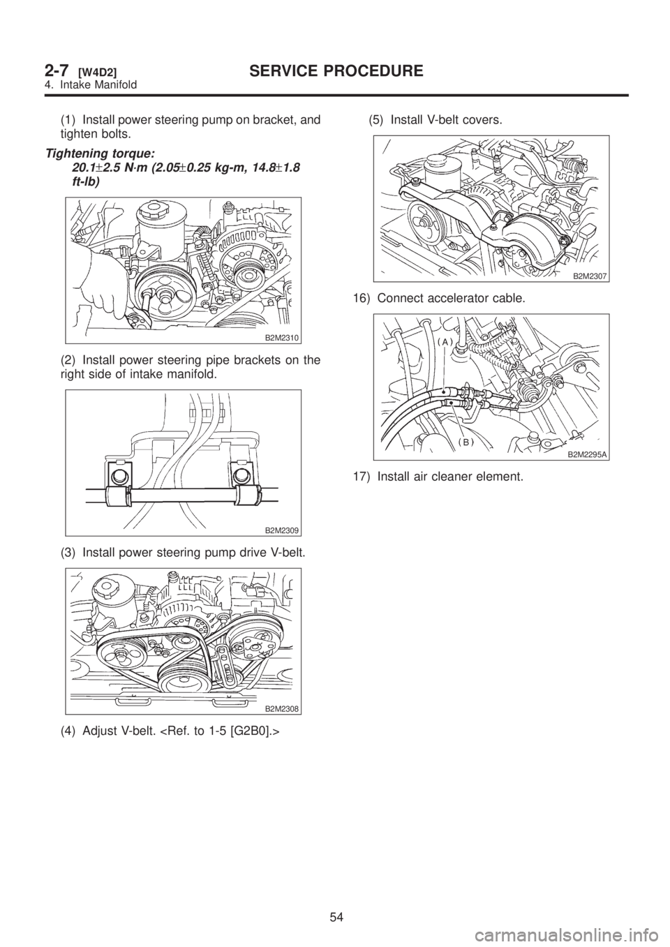
(1) Install power steering pump on bracket, and
tighten bolts.
Tightening torque:
20.1
±2.5 N´m (2.05±0.25 kg-m, 14.8±1.8
ft-lb)
B2M2310
(2) Install power steering pipe brackets on the
right side of intake manifold.
B2M2309
(3) Install power steering pump drive V-belt.
B2M2308
(4) Adjust V-belt. (5) Install V-belt covers.
B2M2307
16) Connect accelerator cable.
B2M2295A
17) Install air cleaner element.
54
2-7[W4D2]SERVICE PROCEDURE
4. Intake Manifold
Page 319 of 1456
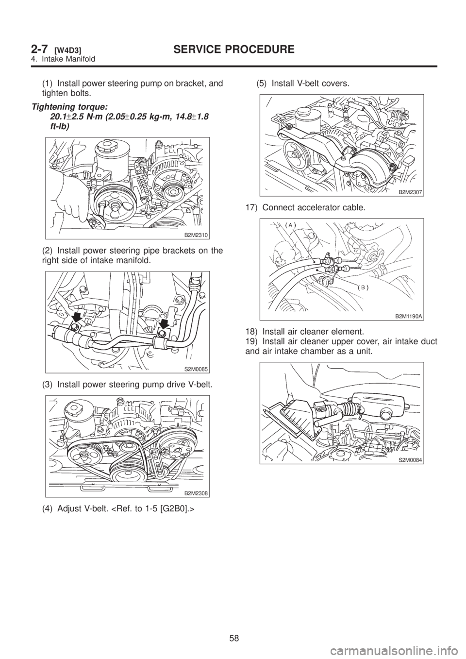
(1) Install power steering pump on bracket, and
tighten bolts.
Tightening torque:
20.1
±2.5 N´m (2.05±0.25 kg-m, 14.8±1.8
ft-lb)
B2M2310
(2) Install power steering pipe brackets on the
right side of intake manifold.
S2M0085
(3) Install power steering pump drive V-belt.
B2M2308
(4) Adjust V-belt. (5) Install V-belt covers.
B2M2307
17) Connect accelerator cable.
B2M1190A
18) Install air cleaner element.
19) Install air cleaner upper cover, air intake duct
and air intake chamber as a unit.
S2M0084
58
2-7[W4D3]SERVICE PROCEDURE
4. Intake Manifold
Page 345 of 1456
(2) Remove resonator chamber.
B2M2306
5) Remove component parts of air intake system.
(Except California spec. vehicles)
(1) Disconnect connector from mass air flow
sensor.
B2M2018
(2) Remove air intake duct and air cleaner
upper cover as a unit, and remove air cleaner
element.
B2M2020
6) Remove spark plug cords from spark plugs (#1
and #3 cylinders).
B2M2014
7) Remove power steering pump from bracket.
(1) Remove V-belt covers.
B2M2307
(2) Loosen lock bolt and slider bolt, and remove
power steering pump drive V-belt.
B2M2308
(3) Remove bolts which secure power steering
pipe brackets to intake manifold.
B2M2309
(4) Remove bolts which install power steering
pump to bracket.
B2M2310
80
2-7[W14A1]SERVICE PROCEDURE
14. Fuel Injector
Page 440 of 1456
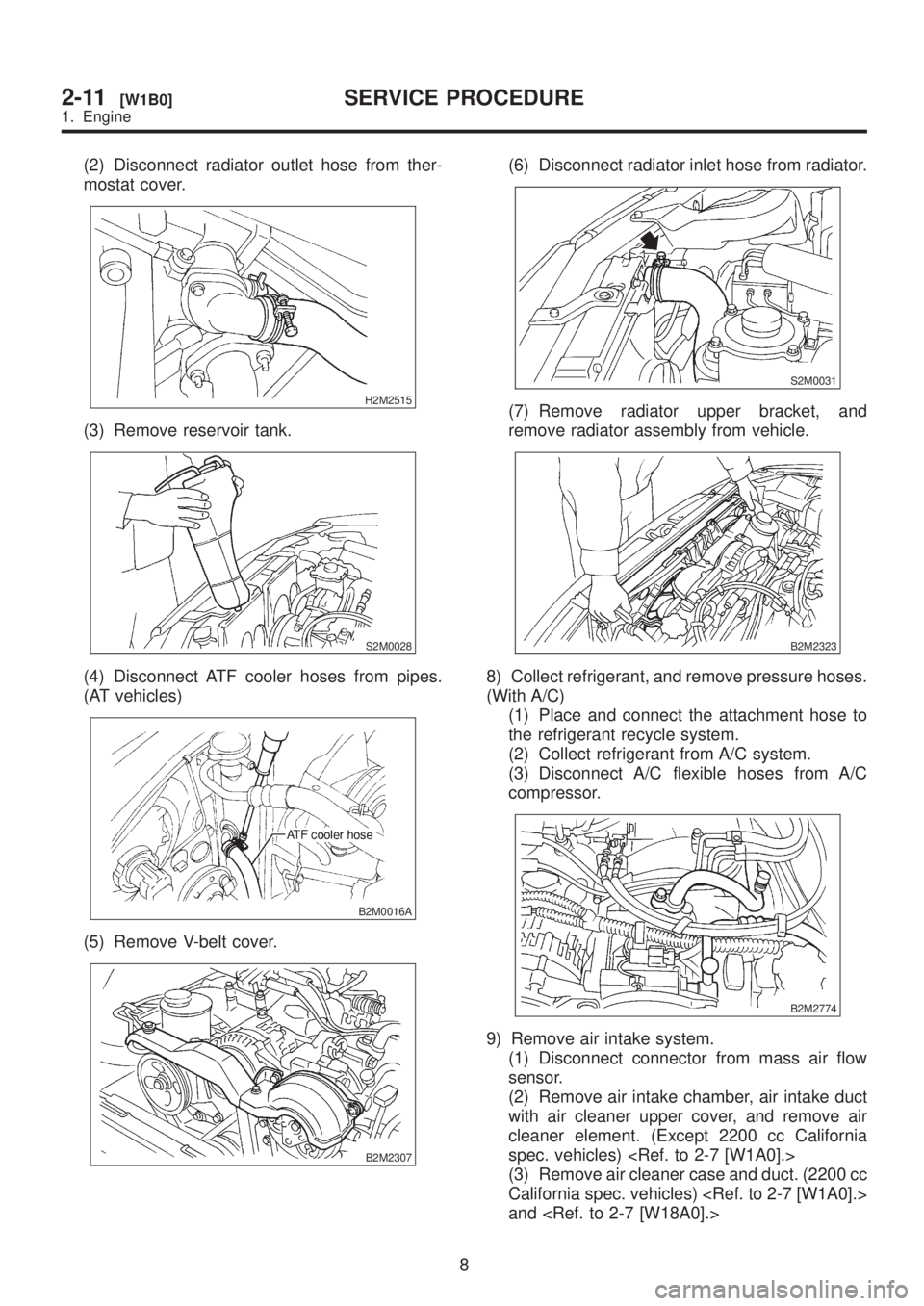
(2) Disconnect radiator outlet hose from ther-
mostat cover.
H2M2515
(3) Remove reservoir tank.
S2M0028
(4) Disconnect ATF cooler hoses from pipes.
(AT vehicles)
B2M0016A
(5) Remove V-belt cover.
B2M2307
(6) Disconnect radiator inlet hose from radiator.
S2M0031
(7) Remove radiator upper bracket, and
remove radiator assembly from vehicle.
B2M2323
8) Collect refrigerant, and remove pressure hoses.
(With A/C)
(1) Place and connect the attachment hose to
the refrigerant recycle system.
(2) Collect refrigerant from A/C system.
(3) Disconnect A/C flexible hoses from A/C
compressor.
B2M2774
9) Remove air intake system.
(1) Disconnect connector from mass air flow
sensor.
(2) Remove air intake chamber, air intake duct
with air cleaner upper cover, and remove air
cleaner element. (Except 2200 cc California
spec. vehicles)
(3) Remove air cleaner case and duct. (2200 cc
California spec. vehicles)
and
8
2-11[W1B0]SERVICE PROCEDURE
1. Engine
Page 446 of 1456
B2M2776AS2M0204A
12) Remove power steering pump from bracket.
(1) Loosen lock bolt and slider bolt, and remove
front side V-belt.
G2M0286
(2) Remove pipe with bracket from intake mani-
fold.
B2M2309
(3) Remove bolts which install power steering
pump from bracket.
S2M0086
(4) Place power steering pump on the right side
wheel apron.
S2M0087
13) Remove front exhaust pipe and center
exhaust pipe.
(1) Lift-up the vehicle.
(2) Disconnect connector from rear oxygen
sensor. (Except 2500cc California spec.
vehicles)
B2M0335
14
2-11[W1B0]SERVICE PROCEDURE
1. Engine
Page 450 of 1456

7) Install canister and bracket.
(1) Install power stering pump on bracket, and
tighten bolts.
Tightening torque:
39
±10 N´m (4.0±1.0 kg-m, 29±7 ft-lb)
S2M0086
(2) Install power steering pipe bracket on right
side intake manifold, and install spark plug
codes.
B2M2309
(3) Install front side V-belt, and adjust it.
G2M0286
8) Tighten nuts which hold lower side of transmis-
sion to engine.
Tightening torque:
50
±4 N´m (5.1±0.4 kg-m, 36.9±2.9 ft-lb)
B2M2790
9) Tighten nuts which install front cushion rubber
onto crossmember.
Tightening torque:
69
±15 N´m (7.0±1.5 kg-m, 51±11 ft-lb)
CAUTION:
Be sure to tighten front cushion rubber mount-
ing bolts in the innermost elliptical hole in the
front crossmember.
G2M0303
10) Install front exhaust pipe and center exhaust
pipe.
11) Connect the following hoses.
(1) Fuel delivery hose, return hose and evapo-
ration hose
(2) Heater inlet and outlet hoses
(3) Brake booster vacuum hose
12) Connect the following connectors.
(1) Engine ground terminal
(2) Engine harness connectors
(3) Front oxygen sensor connector
(4) Rear oxygen sensor connector (California
spec. vehicles)
(5) Alternator connector and terminal
(6) A/C compressor connectors (With A/C)
13) Connect the following cables.
(1) Accelerator cable
(2) Cruise control cables (With cruise control)
(3) Clutch cable (2200 cc MT vehicles)
18
2-11[W1C0]SERVICE PROCEDURE
1. Engine
Page 452 of 1456
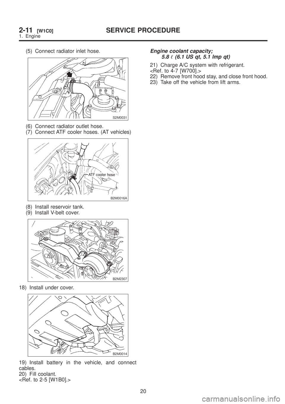
(5) Connect radiator inlet hose.
S2M0031
(6) Connect radiator outlet hose.
(7) Connect ATF cooler hoses. (AT vehicles)
B2M0016A
(8) Install reservoir tank.
(9) Install V-belt cover.
B2M2307
18) Install under cover.
B2M0014
19) Install battery in the vehicle, and connect
cables.
20) Fill coolant.
Engine coolant capacity;
5.8
(6.1 US qt, 5.1 lmp qt)
21) Charge A/C system with refrigerant.
22) Remove front hood stay, and close front hood.
23) Take off the vehicle from lift arms.
20
2-11[W1C0]SERVICE PROCEDURE
1. Engine
Page 787 of 1456

7. Steel Wheel and Tire
A: INSPECTION
1) Deformation or damage on the rim can cause
air leakage. Check the rim flange for deformation,
crack, or damage, and repair or replace as neces-
sary.
2) Take stone, glass, nail etc. off the tread groove.
3) Replace tire:
CAUTION:
IWhen replacing a tire, make sure to use only
the same size, construction and load range as
originally installed.
IAvoid mixing radial, belted bias or bias tires
on the vehicle.
(1) when large crack on side wall, damage or
crack on tread is found.
(2) when the ªtread wear indicatorº appears as
a solid band across the tread.
G4M0297
1. INSPECTION OF WHEEL RUNOUT
1) Jack-up vehicle until wheels clear the floor.
2) Slowly rotate wheel to check rim ªrunoutº using
a dial gauge.
G4M0298
Axial runout limit Radial runout limit
Steel wheel 1.5 mm (0.059 in)
Aluminum wheel 1.0 mm (0.039 in)
G4M0299
3) If rim runout exceeds specifications, remove
tire from rim and check runout while attaching dial
gauge to positions shown in figure.
4) If measured runout still exceeds specifications,
replace the wheel.
39
[W7A1]4-2SERVICE PROCEDURE
7. Steel Wheel and Tire