Page 160 of 1456
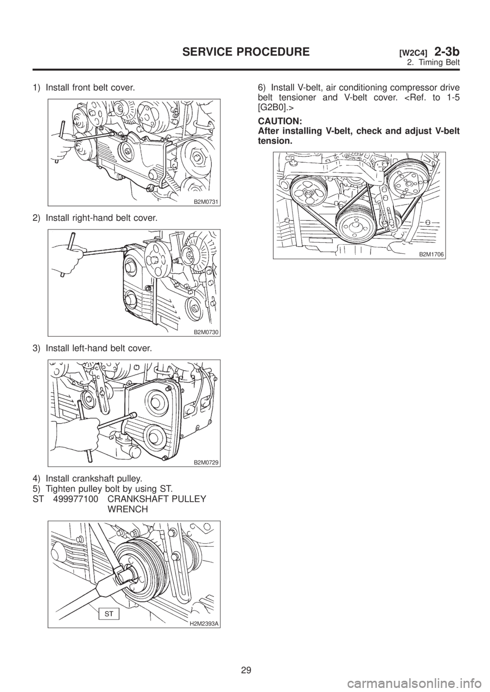
1) Install front belt cover.
B2M0731
2) Install right-hand belt cover.
B2M0730
3) Install left-hand belt cover.
B2M0729
4) Install crankshaft pulley.
5) Tighten pulley bolt by using ST.
ST 499977100 CRANKSHAFT PULLEY
WRENCH
H2M2393A
6) Install V-belt, air conditioning compressor drive
belt tensioner and V-belt cover.
[G2B0].>
CAUTION:
After installing V-belt, check and adjust V-belt
tension.
B2M1706
29
[W2C4]2-3bSERVICE PROCEDURE
2. Timing Belt
Page 161 of 1456
3. Camshaft
A: REMOVAL
1. RELATED PARTS
Remove timing belt, camshaft sprockets and related parts.
2. CAMSHAFT
S2M0298A
(1) Spark plug cord
(2) Rocker cover (LH)
(3) Rocker cover gasket (LH)(4) Intake camshaft cap (LH)
(5) Intake camshaft (LH)
(6) Exhaust camshaft cap (LH)(7) Exhaust camshaft (LH)
1) Remove camshaft position sensor (LH side
only).
2) Remove spark plug cord.
3) Remove rocker cover and gasket.4) Loosen intake camshaft cap bolts equally, a
little at a time in alphabetical sequence shown in
figure.
B2M1393B
5) Remove camshaft caps and intake camshaft.
30
2-3b[W3A1]SERVICE PROCEDURE
3. Camshaft
Page 165 of 1456
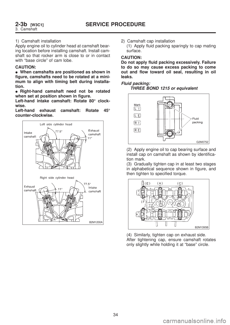
1) Camshaft installation
Apply engine oil to cylinder head at camshaft bear-
ing location before installing camshaft. Install cam-
shaft so that rocker arm is close to or in contact
with ªbase circleº of cam lobe.
CAUTION:
IWhen camshafts are positioned as shown in
figure, camshafts need to be rotated at a mini-
mum to align with timing belt during installa-
tion.
IRight-hand camshaft need not be rotated
when set at position shown in figure.
Left-hand intake camshaft: Rotate 80É clock-
wise.
Left-hand exhaust camshaft: Rotate 45É
counter-clockwise.
B2M1200A
2) Camshaft cap installation
(1) Apply fluid packing sparingly to cap mating
surface.
CAUTION:
Do not apply fluid packing excessively. Failure
to do so may cause excess packing to come
out and flow toward oil seal, resulting in oil
leaks.
Fluid packing:
THREE BOND 1215 or equivalent
G2M0752
(2) Apply engine oil to cap bearing surface and
install cap on camshaft as shown by identifica-
tion mark.
(3) Gradually tighten cap in at least two stages
in alphabetical sequence shown in figure, and
then tighten to specified torque.
B2M1395B
(4) Similarly, tighten cap on exhaust side.
After tightening cap, ensure camshaft rotates
only slightly while holding it at ªbaseº circle.
34
2-3b[W3C1]SERVICE PROCEDURE
3. Camshaft
Page 166 of 1456
3) Camshaft oil seal installation
Apply grease to new oil seal lips and press onto
front end of camshaft by using ST1 and ST2.
CAUTION:
Use a new oil seal.
ST1 499587100 OIL SEAL INSTALLER
ST2 499597000 OIL SEAL GUIDE
G2M0754
4) Rocker cover installation
(1) Install gasket on rocker cover.
Install peripheral gasket and ignition coil gasket.
(2) Apply fluid packing to four front open edges
of peripheral gasket.
Fluid packing:
THREE BOND 1215 or equivalent
S2M0300A
(3) Install rocker cover on cylinder head.
Ensure gasket is properly positioned during
installation.
5) Install ignition coil.
6) Install cam angle sensor.
7) Similarly, install parts on right-hand side.
2. RELATED PARTS
Install timing belt, camshaft sprockets and related
parts.
35
[W3C2]2-3bSERVICE PROCEDURE
3. Camshaft
Page 167 of 1456
4. Cylinder Head
A: REMOVAL
1. RELATED PARTS
1) Remove V-belt.
2) Remove generator, air conditioner compressor
and brackets.
3) Remove hoses and tubes from cylinder block.
4) Disconnect each connector and/or remove con-
nector bracket.5) Remove intake manifold assembly and gasket.
6) Remove camshaft position sensor.
7) Remove timing belt, camshaft sprockets and
related parts.
8) Remove rocker cover, camshafts and related
parts.
2. CYLINDER HEAD
S2M0421A
(1) Bolt
(2) Cylinder head bolt(3) Cylinder head
(4) Cylinder head gasket
1) Remove oil level gauge guide attaching bolt
(LH side only).
36
2-3b[W4A1]SERVICE PROCEDURE
4. Cylinder Head
Page 178 of 1456
3) Install camshaft sprockets, timing belt and related parts.
S2M0303
4) Install intake manifold.
CAUTION:
Use new gaskets.
G2M0774
5) Install camshaft position sensor. Use dry com-
pressed air to remove foreign particles before
installing sensor.
6) Connect each connector and/or install connec-
tor bracket.
7) Connect hoses and tubes to cylinder block.
8) Install brackets, generator and air conditioner
compressor.
9) Install V-belt.
47
[W4E2]2-3bSERVICE PROCEDURE
4. Cylinder Head
Page 179 of 1456
5. Cylinder Block
A: REMOVAL
1. RELATED PARTS
1) Remove timing belt, camshaft sprockets and related parts.
S2M0303
48
2-3b[W5A1]SERVICE PROCEDURE
5. Cylinder Block
Page 201 of 1456
(2) Apply fluid packing to matching surface of
oil pump.
Fluid packing:
THREE BOND 1215 or equivalent
B2M0390A
(3) Install oil pump on cylinder block. Be care-
ful not to damage oil seal during installation.
CAUTION:
IDo not forget to install O-ring and seal when
installing oil pump.
IAlign flat surface of oil pump's inner rotor
with crankshaft before installation.
B2M0390A
9) Install water pump and gasket.
CAUTION:
IBe sure to use a new gasket.
IWhen installing water pump, tighten bolts in
two stages in alphabetical sequence as shown
in figure.
H2M1568A
10) Install water by-pass pipe for heater.
11) Install oil filter.
2. RELATED PARTS
1) Install water pipe.
CAUTION:
Always use a new O-ring.
S2M0308A
2) Install cylinder heads.
3) Install camshafts, rocker cover and related
parts.
4) Install camshaft sprockets, timing belt and
related parts.
70
2-3b[W5E2]SERVICE PROCEDURE
5. Cylinder Block