Page 80 of 1456
(1) Replace the crankshaft pulley bolts and
clean them.
Crankshaft pulley bolt:
12369AA011
(2) Clean the crankshaft thread using an air
gun.
(3) Tighten the bolts temporarily with tightening
torque of 44 N´m (4.5 kg-m, 33 ft-lb).
(4) Tighten the crankshaft pulley bolts keeping
them in an angle between 45 degrees and 60
degrees.
CAUTION:
Conduct the tightening procedures by confirm-
ing the turning angle of the crankshaft pulley
bolt referring to the gauge indicated on the belt
cover.
6) Install A/C belt tensioner. (With A/C model)
B2M2585
7) Install A/C belt. (With A/C model)
B2M2584
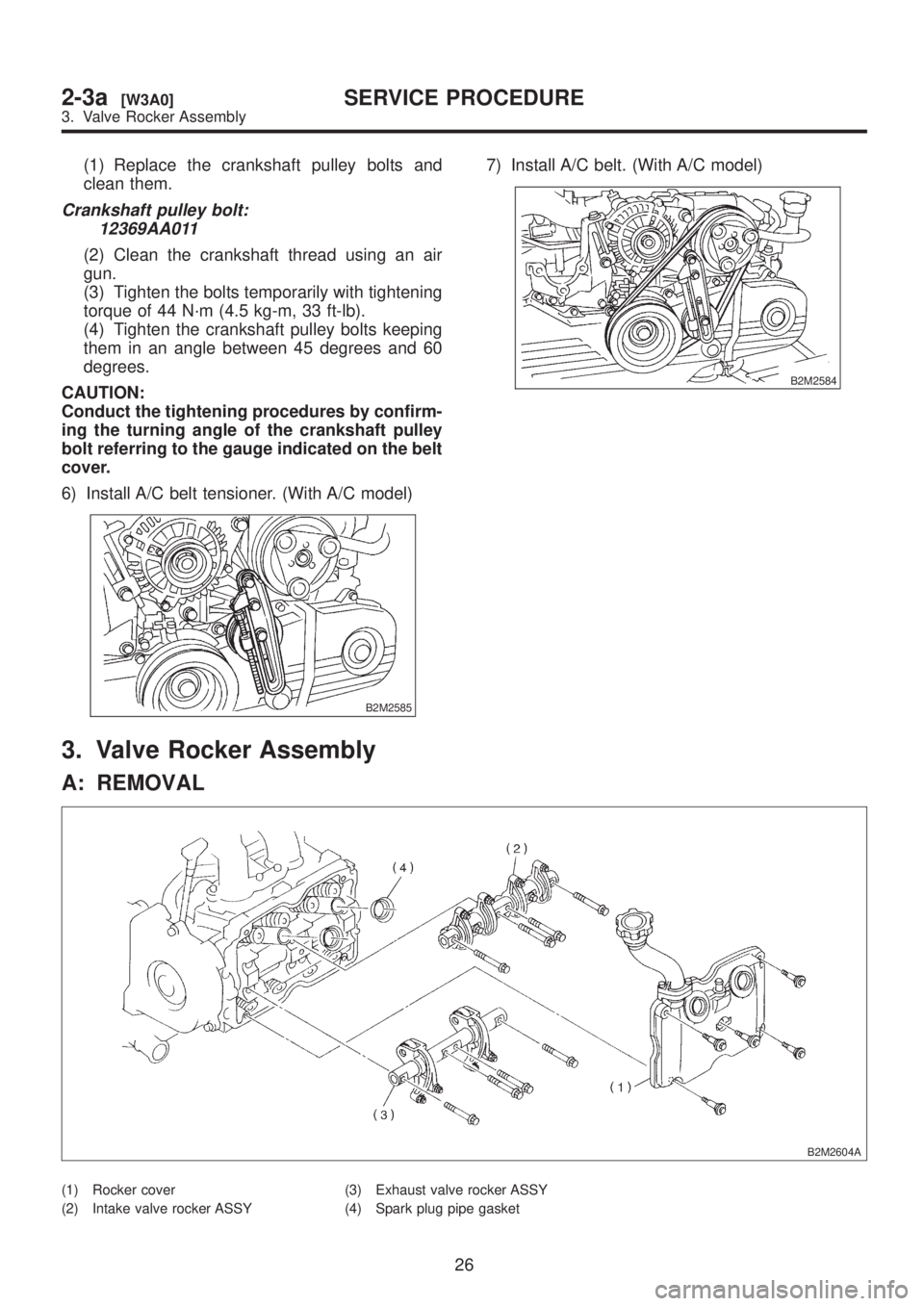
3. Valve Rocker Assembly
A: REMOVAL
B2M2604A
(1) Rocker cover
(2) Intake valve rocker ASSY(3) Exhaust valve rocker ASSY
(4) Spark plug pipe gasket
26
2-3a[W3A0]SERVICE PROCEDURE
3. Valve Rocker Assembly
Page 86 of 1456
4. Camshaft
A: REMOVAL
1. RELATED PARTS
Remove timing belt, camshaft sprockets and
related parts.
2. CAMSHAFT (LH)
B2M2610A
(1) Bolt
(2) Oil level gauge guide(3) Camshaft cap
(4) Camshaft (LH)(5) Oil seal
(6) Plug
1) Remove camshaft position sensor.
CAUTION:
Do not damage the camshaft position sensor.
2) Remove oil level gauge guide attaching bolt.
3) Remove oil level gauge guide.
4) Remove camshaft position sensor support.
5) Remove camshaft cap.
(1) Remove valve rocker assembly.
B2M2606
(2) Remove bolts (a) through (b) in alphabetical
sequence.
B2M2612A
32
2-3a[W4A1]SERVICE PROCEDURE
4. Camshaft
Page 93 of 1456
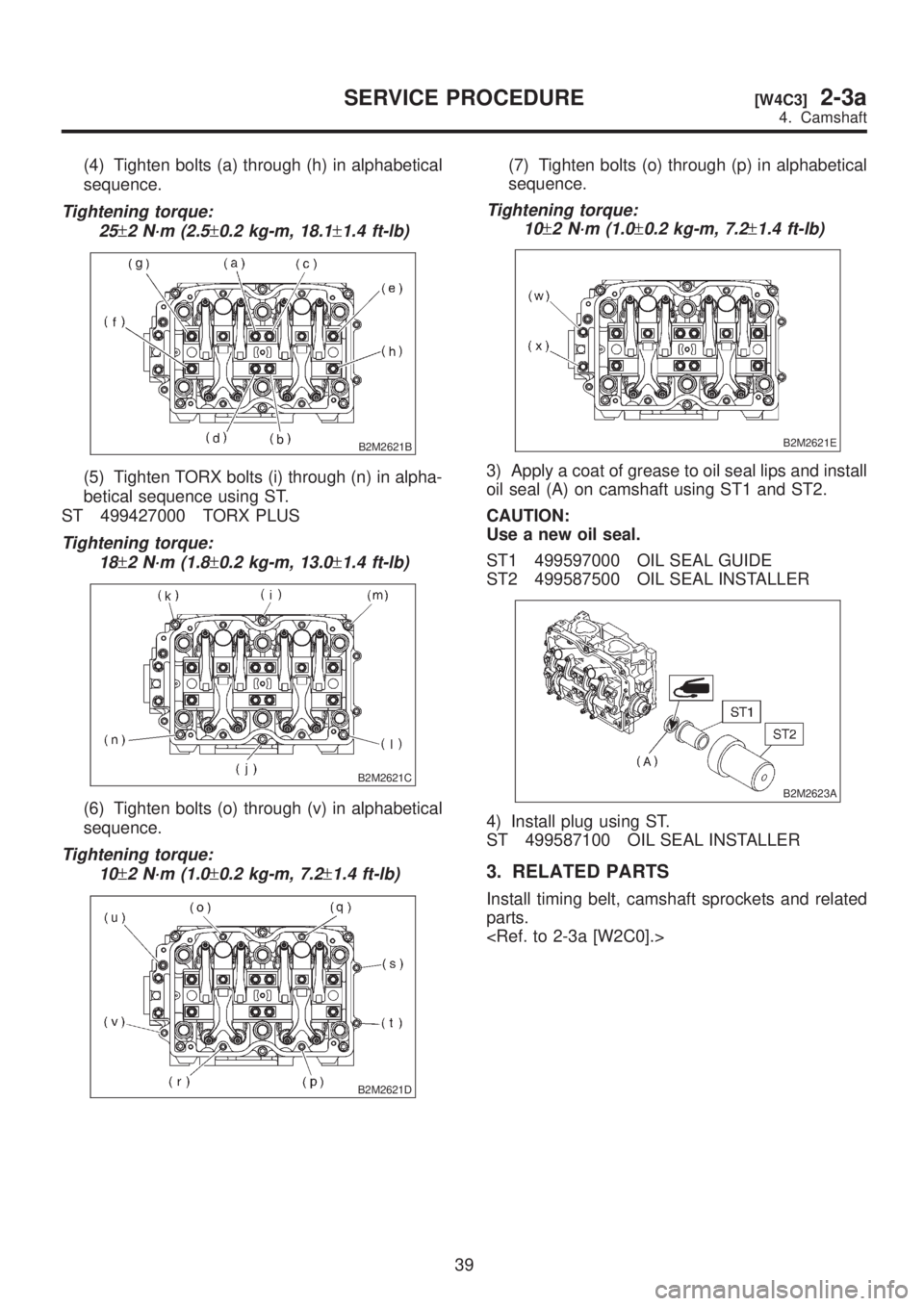
(4) Tighten bolts (a) through (h) in alphabetical
sequence.
Tightening torque:
25
±2 N´m (2.5±0.2 kg-m, 18.1±1.4 ft-lb)
B2M2621B
(5) Tighten TORX bolts (i) through (n) in alpha-
betical sequence using ST.
ST 499427000 TORX PLUS
Tightening torque:
18
±2 N´m (1.8±0.2 kg-m, 13.0±1.4 ft-lb)
B2M2621C
(6) Tighten bolts (o) through (v) in alphabetical
sequence.
Tightening torque:
10
±2 N´m (1.0±0.2 kg-m, 7.2±1.4 ft-lb)
B2M2621D
(7) Tighten bolts (o) through (p) in alphabetical
sequence.
Tightening torque:
10
±2 N´m (1.0±0.2 kg-m, 7.2±1.4 ft-lb)
B2M2621E
3) Apply a coat of grease to oil seal lips and install
oil seal (A) on camshaft using ST1 and ST2.
CAUTION:
Use a new oil seal.
ST1 499597000 OIL SEAL GUIDE
ST2 499587500 OIL SEAL INSTALLER
B2M2623A
4) Install plug using ST.
ST 499587100 OIL SEAL INSTALLER
3. RELATED PARTS
Install timing belt, camshaft sprockets and related
parts.
39
[W4C3]2-3aSERVICE PROCEDURE
4. Camshaft
Page 94 of 1456
5. Cylinder Head
A: REMOVAL
1. RELATED PARTS
1) Release fuel pressure.
2) Drain engine coolant.
3) Remove V-belt(s).
4) Remove generator and bracket.
5) Remove A/C compressor and bracket. (With
A/C model)6) Disconnect spark plug cords.
7) Remove connector bracket attaching bolt.
8) Remove camshaft position sensor and cam-
shaft position sensor support.
9) Disconnect oil pressure switch connector.
10) Disconnect blow-by hose.
11) Remove intake manifold.
[W4A0].>
2. CYLINDER HEAD
B2M2627A
(1) Rocker cover
(2) Cylinder head bolt(3) Cylinder head
(4) Cylinder head gasket
1) Remove timing belt, camshaft sprocket and
related parts.
2) Remove oil level gauge guide attaching bolt
(left hand only) and oil level gauge guide.
3) Remove rocker cover.
40
2-3a[W5A1]SERVICE PROCEDURE
5. Cylinder Head
Page 104 of 1456

2) Tighten cylinder head bolts.
(1) Apply a coat of engine oil to washers and
bolt threads.
(2) Tighten all bolts to 29 N´m (3.0 kg-m, 22
ft-lb) in alphabetical sequence.
Then tighten all bolts to 69 N´m (7.0 kg-m, 51
ft-lb) in alphabetical sequence.
(3) Back off all bolts by 180É first; back them off
by 180É again.
(4) Tighten bolts (a) and (b) to 34 N´m (3.5
kg-m, 25 ft-lb).
(5) Tighten bolts (c), (d), (e) and (f) to 15 N´m
(1.5 kg-m, 11 ft-lb).
(6) Tighten all bolts by 80 to 90É in alphabetical
sequence.
CAUTION:
Do not tighten bolts more than 90É.
(7) Further tighten all bolts by 80 to 90É in
alphabetical sequence.
CAUTION:
Ensure that the total ªre-tightening angleº [in
the former two steps], do not exceed 180É.
B2M2628B
3) Install oil level gauge guide and tighten attach-
ing bolt (left side only).
4) Install timing belt, camshaft sprocket and
related parts.
2. RELATED PARTS
CAUTION:
Be careful not to scratch the mating surface of
cylinder block and oil pump.
1) Install engine coolant pipe.
2) Install intake manifold.
3) Connect blow-by hose.
4) Connect oil pressure switch connector.
5) Install camshaft position sensor and camshaft
position sensor support.
6) Install connector bracket attaching bolt.
7) Connect spark plug cords.
8) Install generator and bracket.
9) Install A/C compressor and bracket. (With A/C
model)
10) Install V-belt(s).
11) Remove ENGINE STAND (ST).
50
2-3a[W5E2]SERVICE PROCEDURE
5. Cylinder Head
Page 105 of 1456
6. Cylinder Block
A: REMOVAL
1. RELATED PARTS
1) Remove timing belt, camshaft sprockets and
related parts.
2) Remove cylinder heads.
[W5A0].>
3) Remove water pipe.
B2M2638
51
[W6A1]2-3aSERVICE PROCEDURE
6. Cylinder Block
Page 126 of 1456
(2) Apply fluid packing to matching surface of
oil pump.
Fluid packing:
THREE BOND 1215 or equivalent
S2M0739A
(3) Apply a coat of engine oil to the inside of the
oil seal.
S2M0118A
(4) Install oil pump on cylinder block. Be care-
ful not to damage oil seal during installation.
CAUTION:
IDo not forget to install O-ring and seal when
installing oil pump.
IAlign flat surface of oil pump's inner rotor
with crankshaft before installation.
9) Install water pump and gasket.
CAUTION:
IBe sure to use a new gasket.
IWhen installing water pump, tighten bolts in
two stages in alphabetical sequence as shown
in figure.
H2M1568B
10) Install water by-pass pipe for heater.
11) Install oil filter using ST.
ST 498187300 OIL FILTER WRENCH
B2M2611A
2. RELATED PARTS
1) Install cylinder head, valve rocker assembly
and rocker cover.
2) Install timing belt and camshaft sprocket.
3) Install water pipe.
4) Install intake manifold.
72
2-3a[W6E2]SERVICE PROCEDURE
6. Cylinder Block
Page 127 of 1456

1. Engine Trouble in General
NOTE:
ªRANKº shown in the chart refer to the possibility of reason for the trouble in order (ªVery oftenº to ªRarelyº)
A Ð Very often
B Ð Sometimes
C Ð Rarely
TROUBLE PROBLEM PARTS, ETC. POSSIBLE CAUSE RANK
1. Engine will not start.
1) Starter does not turn.IStarterIDefective battery-to-starter harness B
IDefective starter switch C
IDefective inhibitor switch or neutral switch C
IDefective starter B
IBatteryIPoor terminal connecton A
IRun-down battrey A
IDefective charging system B
IFrictionISeizure of crankshaft and connecting rod bearing C
ISeized camshaft C
ISeized or stuck piston and cylinder C
2) Initial combustion does
not occur.IStarterIDefective starter C
IFuel injection system A
IFuel lineIDefective fuel pump and relay A
ILack of or insufficient fuel B
IBeltIDefective B
IDefective timing B
ICompressionIIncorrect valve clearance C
ILoosened spark plugs or defective gasket C
ILoosened cylinder head bolts or defective gasket C
IImproper valve seating C
IDefective valve stem C
IWorn or broken valve spring B
IWorn or stuck piston rings, cylinder and piston C
IIncorrect valve timing B
IImproper engine oil (low viscosity) B
3) Initial combustion occur.IFuel injection system A
IIntake systemIDefective intake manifold gasket B
IDefective throttle body gasket B
IFuel lineIDefective fuel pump and relay C
IClogged fuel line C
ILack of or insufficient fuel B
IBeltIDefective B
IDefective timing B
ICompressionIIncorrect valve clearance C
ILoosened spark plugs or defective gasket C
ILoosened cylinder head bolts or defective gasket C
IImproper valve seating C
IDefective valve stem C
IWorn or broken valve spring B
IWorn or stuck piston rings, cylinder and piston C
IIncorrect valve timing B
IImproper engine oil (low viscosity) B
73
[K100]2-3aDIAGNOSTICS
1. Engine Trouble in General