Page 869 of 1456

Trouble Possible cause Corrective action
Rattling noise (intermittent)
While engine is running.Interference with adjacent parts Check clearance.
Correct if necessary.
Loosened installation of oil pump, oil tank, pump bracket, gear-
box or crossmemberRetighten.
Loosened installation of oil pump pulley or other pulley(s) Retighten.
Loosened linkage or play of steering or suspension
Loosened tightening of joint or steering columnRetighten or replace.
Sound generates from the inside of gearbox or oil pump. Replace the gearbox or oil
pump.
Knocking
When turning steering wheel
in both direction with small
angle repeatedly at engine
ON or OFF.Excessive backlash
Loosened lock nut for adjusting backlashAdjust and retighten.
Loosened tightening or play of tie-rod, tie-rod end Retighten or replace.
Grinding noise (continuous)
While engine is running.Vane pump aeration Inspect and retighten fluid line
connection.
Refill fluid and vent air.
Vane pump seizing Replace oil pump.
Pulley bearing seizing of oil pump Replace oil pump.
Folded hose, flat pipe Replace.
Squeal, squeak (intermittent
or continuous)
While engine is running.Maladjustment of pulley belt
Damaged or charged pulley belt
Unequal length of pulley beltsAdjust or replace.
(Replace two belts as a set.)
Run out or soilage of V-groove surface of oil pump pulley Clean or replace.
Sizzling noise (continuous)
While engine is running.Fluid aeration Fix wrong part causing aera-
tion.
Replace fluid and vent air.
Damaged pipe of gearbox Replace pipe.
Abnormal inside of hose or pipe
Flat hose or pipeRectify or replace.
Abnormal inside of oil tank Replace.
Removed oil tank cap Install cap.
Whistle (continuous)
While engine is running.Abnormal pipe of gearbox or abnormal inside of hose Replace bad parts of gearbox
or hose.
Whine or growl (continuous or
intermittent)
While engine is running with/
without steering turned.Loosened installation of oil pump, oil pump bracket Retighten.
Abnormal inside of oil pump, hose Replace oil pump, hose, if the
noise can be heard when run-
ning as well as stand still.
Torque converter growl air conditioner compression growl Remove power steering pul-
ley belt and confirm.
Creaking noise (intermittent)
While engine is running with
steering turned.Abnormal inside of gearbox Replace bad parts of gear-
box.
Abnormal bearing for steering shaft Apply grease or replace.
Generates when turning steering wheel with brake (service or
parking) applied.If the noise goes off when
brake is released, it is normal.
Vibration
While engine is running with/
without steering turned.Too low engine speed at start Adjust and instruct custom-
ers.
Vane pump aeration Fix wrong part.
Vent air.
Damaged valve in oil pump, gearbox Replace oil pump, bad parts
of gearbox.
Looseness of play of steering, suspension parts Retighten.
75
[K1E0]4-3DIAGNOSTICS
1. Power Steering
Page 976 of 1456
1. Air Conditioning System
A: SPECIFICATIONS
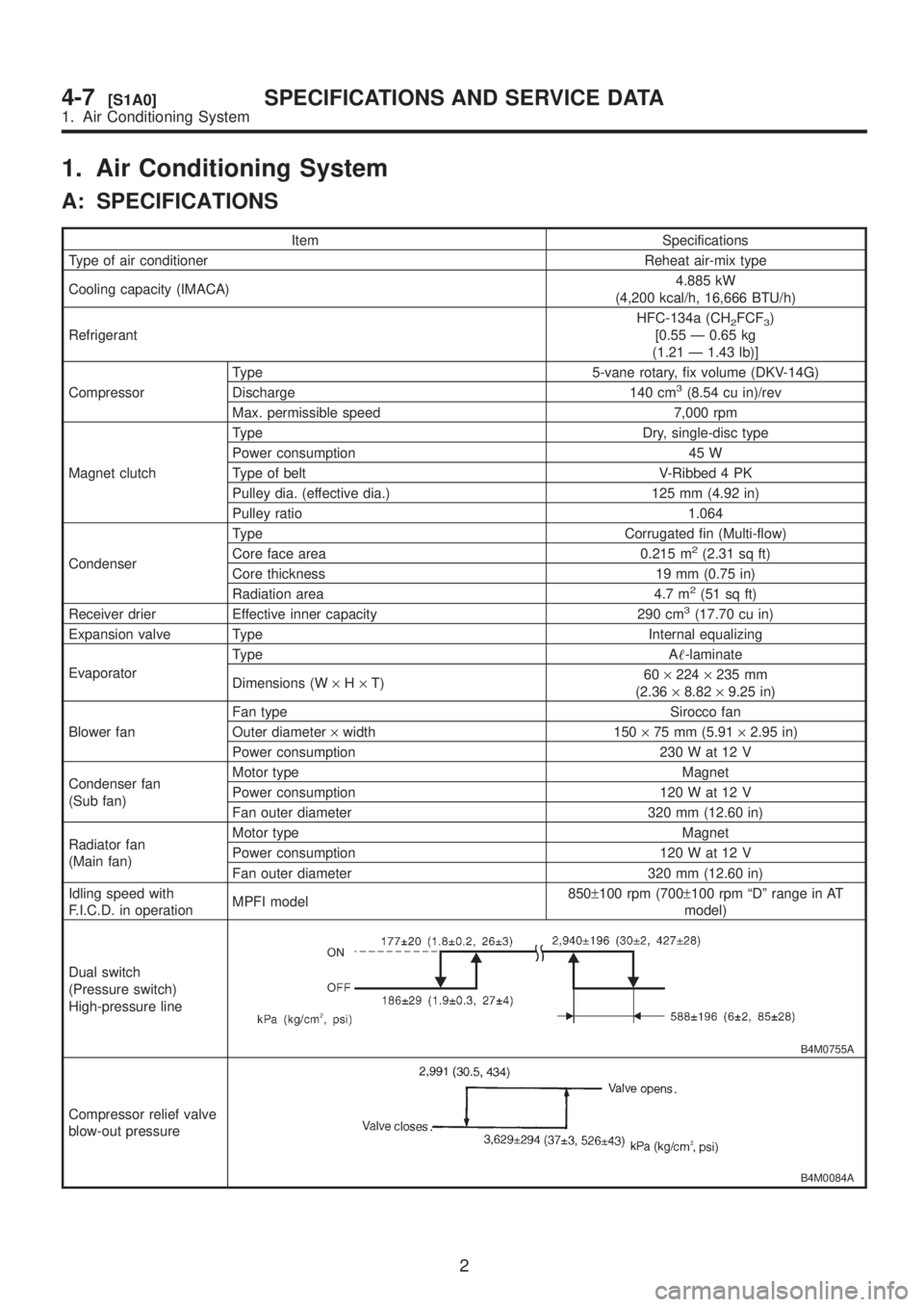
Item Specifications
Type of air conditioner Reheat air-mix type
Cooling capacity (IMACA)4.885 kW
(4,200 kcal/h, 16,666 BTU/h)
RefrigerantHFC-134a (CH
2FCF3)
[0.55 Ð 0.65 kg
(1.21 Ð 1.43 lb)]
CompressorType 5-vane rotary, fix volume (DKV-14G)
Discharge 140 cm
3(8.54 cu in)/rev
Max. permissible speed 7,000 rpm
Magnet clutchType Dry, single-disc type
Power consumption 45 W
Type of belt V-Ribbed 4 PK
Pulley dia. (effective dia.) 125 mm (4.92 in)
Pulley ratio 1.064
CondenserType Corrugated fin (Multi-flow)
Core face area 0.215 m
2(2.31 sq ft)
Core thickness 19 mm (0.75 in)
Radiation area 4.7 m
2(51 sq ft)
Receiver drier Effective inner capacity 290 cm3(17.70 cu in)
Expansion valve Type Internal equalizing
EvaporatorType A-laminate
Dimensions (W´H´T)60´224´235 mm
(2.36´8.82´9.25 in)
Blower fanFan type Sirocco fan
Outer diameter´width 150´75 mm (5.91´2.95 in)
Power consumption 230 W at 12 V
Condenser fan
(Sub fan)Motor type Magnet
Power consumption 120 W at 12 V
Fan outer diameter 320 mm (12.60 in)
Radiator fan
(Main fan)Motor type Magnet
Power consumption 120 W at 12 V
Fan outer diameter 320 mm (12.60 in)
Idling speed with
F.I.C.D. in operationMPFI model850±100 rpm (700±100 rpm ªDº range in AT
model)
Dual switch
(Pressure switch)
High-pressure line
B4M0755A
Compressor relief valve
blow-out pressure
B4M0084A
2
4-7[S1A0]SPECIFICATIONS AND SERVICE DATA
1. Air Conditioning System
Page 1001 of 1456
11. Compressor
A: INSPECTION
1. COMPRESSOR CLUTCH
NOTE:
ICompressor is a swash plate type. When trouble
occurs, replace compressor as a single unit.
ICompressor clutch trouble is often caused by
clutch slippage and noise. Check and take correc-
tive measures, as required.
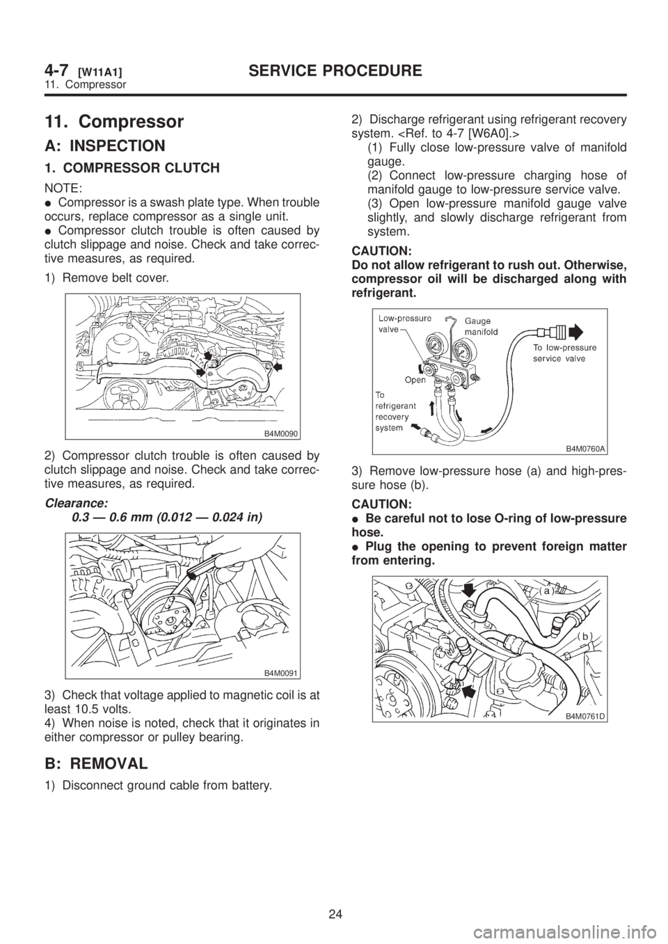
1) Remove belt cover.
B4M0090
2) Compressor clutch trouble is often caused by
clutch slippage and noise. Check and take correc-
tive measures, as required.
Clearance:
0.3 Ð 0.6 mm (0.012 Ð 0.024 in)
B4M0091
3) Check that voltage applied to magnetic coil is at
least 10.5 volts.
4) When noise is noted, check that it originates in
either compressor or pulley bearing.
B: REMOVAL
1) Disconnect ground cable from battery.2) Discharge refrigerant using refrigerant recovery
system.
(1) Fully close low-pressure valve of manifold
gauge.
(2) Connect low-pressure charging hose of
manifold gauge to low-pressure service valve.
(3) Open low-pressure manifold gauge valve
slightly, and slowly discharge refrigerant from
system.
CAUTION:
Do not allow refrigerant to rush out. Otherwise,
compressor oil will be discharged along with
refrigerant.
B4M0760A
3) Remove low-pressure hose (a) and high-pres-
sure hose (b).
CAUTION:
IBe careful not to lose O-ring of low-pressure
hose.
IPlug the opening to prevent foreign matter
from entering.
B4M0761D
24
4-7[W11A1]SERVICE PROCEDURE
11. Compressor
Page 1002 of 1456
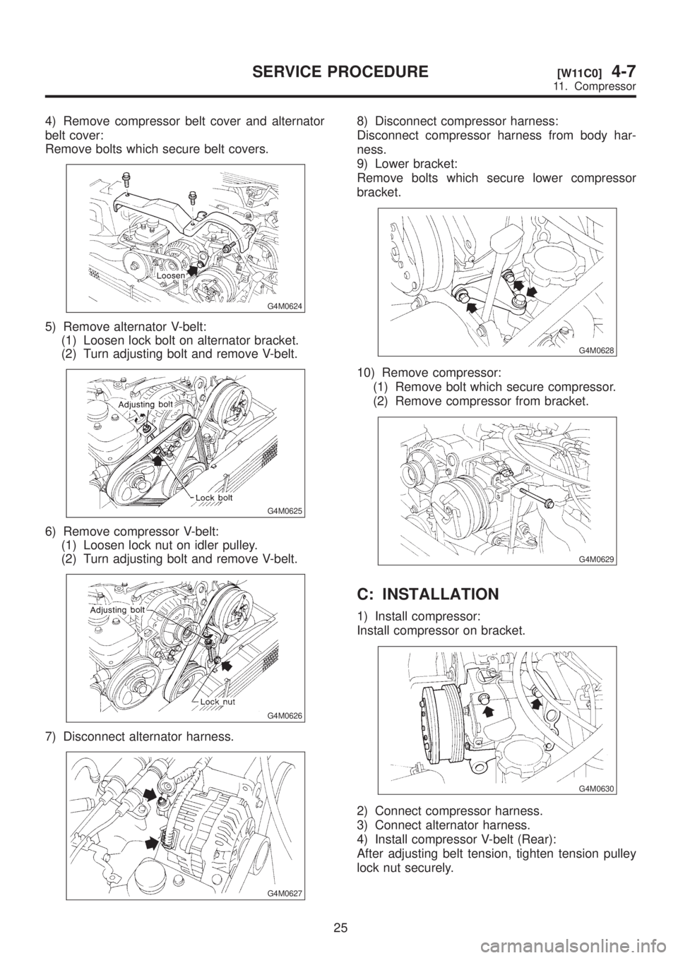
4) Remove compressor belt cover and alternator
belt cover:
Remove bolts which secure belt covers.
G4M0624
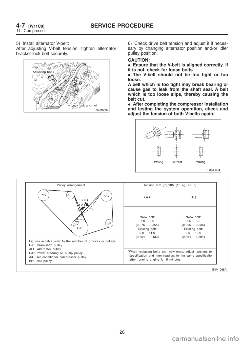
5) Remove alternator V-belt:
(1) Loosen lock bolt on alternator bracket.
(2) Turn adjusting bolt and remove V-belt.
G4M0625
6) Remove compressor V-belt:
(1) Loosen lock nut on idler pulley.
(2) Turn adjusting bolt and remove V-belt.
G4M0626
7) Disconnect alternator harness.
G4M0627
8) Disconnect compressor harness:
Disconnect compressor harness from body har-
ness.
9) Lower bracket:
Remove bolts which secure lower compressor
bracket.
G4M0628
10) Remove compressor:
(1) Remove bolt which secure compressor.
(2) Remove compressor from bracket.
G4M0629
C: INSTALLATION
1) Install compressor:
Install compressor on bracket.
G4M0630
2) Connect compressor harness.
3) Connect alternator harness.
4) Install compressor V-belt (Rear):
After adjusting belt tension, tighten tension pulley
lock nut securely.
25
[W11C0]4-7SERVICE PROCEDURE
11. Compressor
Page 1003 of 1456
5) Install alternator V-belt:
After adjusting V-belt tension, tighten alternator
bracket lock bolt securely.
G4M0632
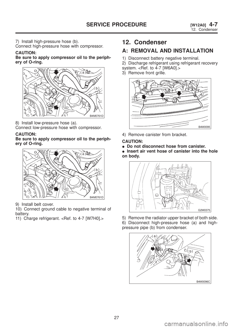
6) Check drive belt tension and adjust it if neces-
sary by changing alternator position and/or idler
pulley position.
CAUTION:
IEnsure that the V-belt is aligned correctly. If
it is not, check for loose bolts.
IThe V-belt should not be too tight or too
loose.
A belt which is too tight may break bearing or
cause gas to leak from the shaft seal. A belt
which is too loose slips, thereby causing the
belt cut.
IAfter completing the compressor installation
and testing the system operation, check and
adjust the tension of both V-belts again.
G4M0634
B4M1098A
26
4-7[W11C0]SERVICE PROCEDURE
11. Compressor
Page 1004 of 1456
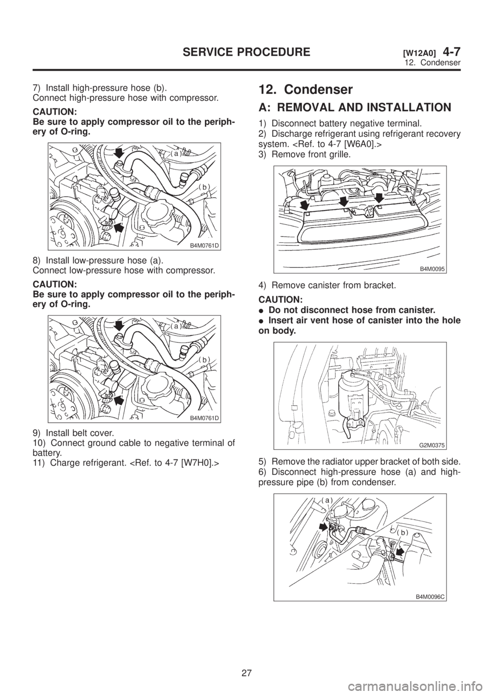
7) Install high-pressure hose (b).
Connect high-pressure hose with compressor.
CAUTION:
Be sure to apply compressor oil to the periph-
ery of O-ring.
B4M0761D
8) Install low-pressure hose (a).
Connect low-pressure hose with compressor.
CAUTION:
Be sure to apply compressor oil to the periph-
ery of O-ring.
B4M0761D
9) Install belt cover.
10) Connect ground cable to negative terminal of
battery.
11) Charge refrigerant.
12. Condenser
A: REMOVAL AND INSTALLATION
1) Disconnect battery negative terminal.
2) Discharge refrigerant using refrigerant recovery
system.
3) Remove front grille.
B4M0095
4) Remove canister from bracket.
CAUTION:
IDo not disconnect hose from canister.
IInsert air vent hose of canister into the hole
on body.
G2M0375
5) Remove the radiator upper bracket of both side.
6) Disconnect high-pressure hose (a) and high-
pressure pipe (b) from condenser.
B4M0096C
27
[W12A0]4-7SERVICE PROCEDURE
12. Condenser
Page 1005 of 1456
7) Install high-pressure hose (b).
Connect high-pressure hose with compressor.
CAUTION:
Be sure to apply compressor oil to the periph-
ery of O-ring.
B4M0761D
8) Install low-pressure hose (a).
Connect low-pressure hose with compressor.
CAUTION:
Be sure to apply compressor oil to the periph-
ery of O-ring.
B4M0761D
9) Install belt cover.
10) Connect ground cable to negative terminal of
battery.
11) Charge refrigerant.
12. Condenser
A: REMOVAL AND INSTALLATION
1) Disconnect battery negative terminal.
2) Discharge refrigerant using refrigerant recovery
system.
3) Remove front grille.
B4M0095
4) Remove canister from bracket.
CAUTION:
IDo not disconnect hose from canister.
IInsert air vent hose of canister into the hole
on body.
G2M0375
5) Remove the radiator upper bracket of both side.
6) Disconnect high-pressure hose (a) and high-
pressure pipe (b) from condenser.
B4M0096C
27
[W12A0]4-7SERVICE PROCEDURE
12. Condenser
Page 1027 of 1456
(52) Front seat belt adjust plate
attaching hole 12 mm (0.47 in)
dia.
(53) Rear door hinge middle hole 10
mm (0.39 in) dia.(54) Rear floor, near door 8 mm (0.31
in) dia.
(55) Trim upper attaching hole at 6
light 8 mm (0.31 in) dia.(56) Trim lower attaching hole at 6
light 8 mm (0.31 in) dia.
(58) Rear floor, near floor strut 15´
20 mm (0.59´0.79 in) dia.
oblong hole
4
5-1[S2A0]SPECIFICATIONS AND SERVICE DATA
2. Body Datum Points