1999 SUBARU LEGACY ground clearance
[x] Cancel search: ground clearancePage 42 of 1456
S2M0242
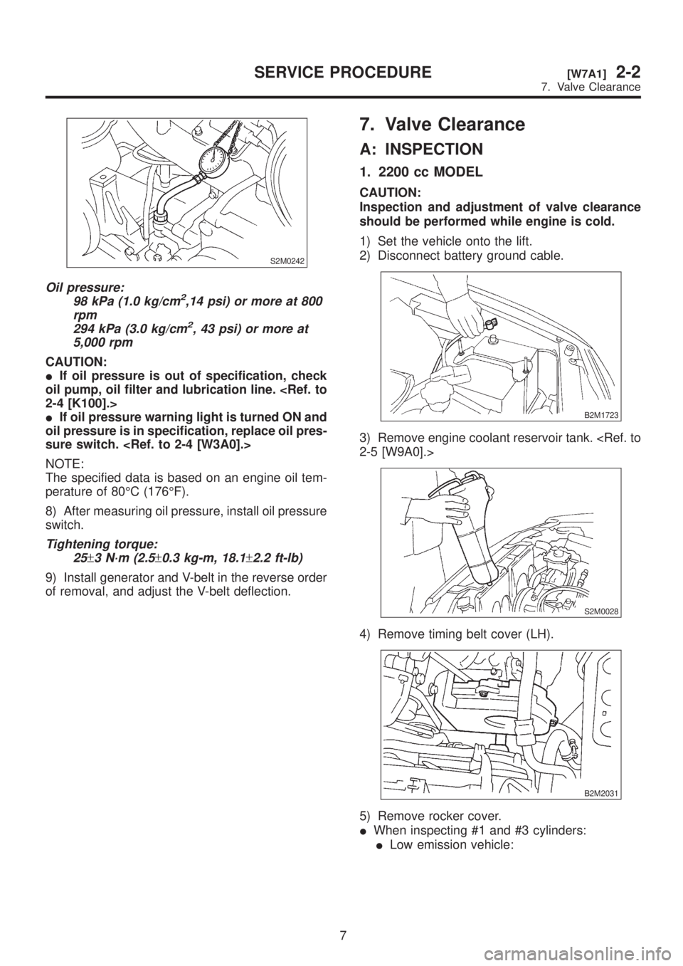
Oil pressure:
98 kPa (1.0 kg/cm2,14 psi) or more at 800
rpm
294 kPa (3.0 kg/cm
2, 43 psi) or more at
5,000 rpm
CAUTION:
IIf oil pressure is out of specification, check
oil pump, oil filter and lubrication line.
IIf oil pressure warning light is turned ON and
oil pressure is in specification, replace oil pres-
sure switch.
NOTE:
The specified data is based on an engine oil tem-
perature of 80ÉC (176ÉF).
8) After measuring oil pressure, install oil pressure
switch.
Tightening torque:
25
±3 N´m (2.5±0.3 kg-m, 18.1±2.2 ft-lb)
9) Install generator and V-belt in the reverse order
of removal, and adjust the V-belt deflection.
7. Valve Clearance
A: INSPECTION
1. 2200 cc MODEL
CAUTION:
Inspection and adjustment of valve clearance
should be performed while engine is cold.
1) Set the vehicle onto the lift.
2) Disconnect battery ground cable.
B2M1723
3) Remove engine coolant reservoir tank.
S2M0028
4) Remove timing belt cover (LH).
B2M2031
5) Remove rocker cover.
IWhen inspecting #1 and #3 cylinders:
ILow emission vehicle:
7
[W7A1]2-2SERVICE PROCEDURE
7. Valve Clearance
Page 43 of 1456
S2M0242
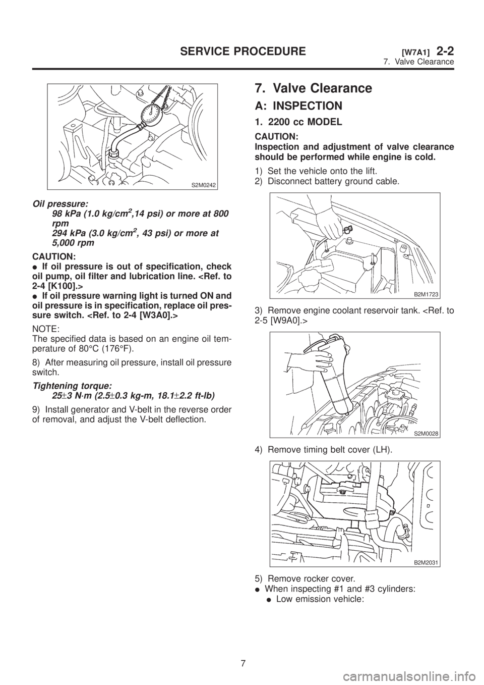
Oil pressure:
98 kPa (1.0 kg/cm2,14 psi) or more at 800
rpm
294 kPa (3.0 kg/cm
2, 43 psi) or more at
5,000 rpm
CAUTION:
IIf oil pressure is out of specification, check
oil pump, oil filter and lubrication line.
IIf oil pressure warning light is turned ON and
oil pressure is in specification, replace oil pres-
sure switch.
NOTE:
The specified data is based on an engine oil tem-
perature of 80ÉC (176ÉF).
8) After measuring oil pressure, install oil pressure
switch.
Tightening torque:
25
±3 N´m (2.5±0.3 kg-m, 18.1±2.2 ft-lb)
9) Install generator and V-belt in the reverse order
of removal, and adjust the V-belt deflection.
7. Valve Clearance
A: INSPECTION
1. 2200 cc MODEL
CAUTION:
Inspection and adjustment of valve clearance
should be performed while engine is cold.
1) Set the vehicle onto the lift.
2) Disconnect battery ground cable.
B2M1723
3) Remove engine coolant reservoir tank.
S2M0028
4) Remove timing belt cover (LH).
B2M2031
5) Remove rocker cover.
IWhen inspecting #1 and #3 cylinders:
ILow emission vehicle:
7
[W7A1]2-2SERVICE PROCEDURE
7. Valve Clearance
Page 47 of 1456
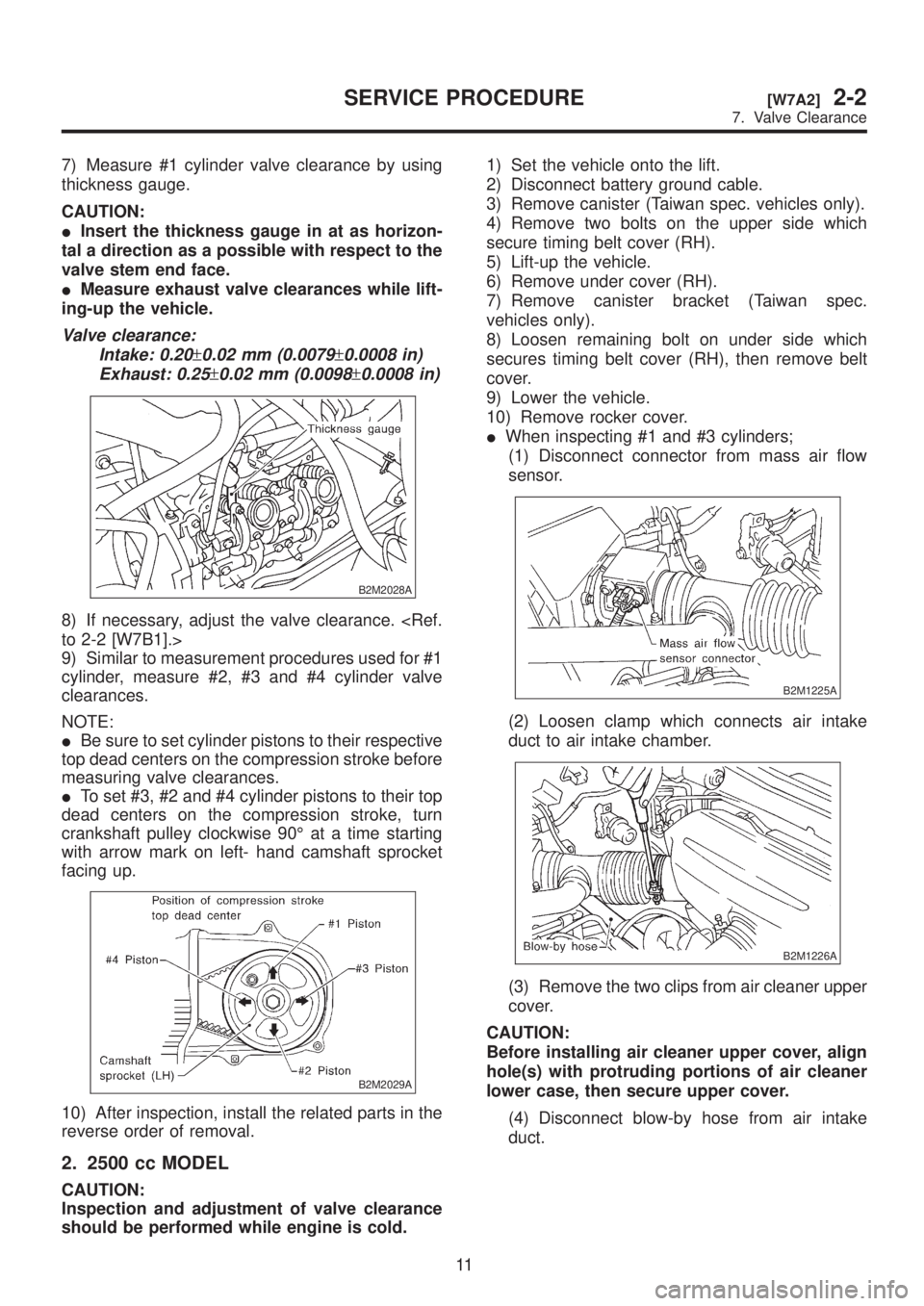
7) Measure #1 cylinder valve clearance by using
thickness gauge.
CAUTION:
IInsert the thickness gauge in at as horizon-
tal a direction as a possible with respect to the
valve stem end face.
IMeasure exhaust valve clearances while lift-
ing-up the vehicle.
Valve clearance:
Intake: 0.20
±0.02 mm (0.0079±0.0008 in)
Exhaust: 0.25
±0.02 mm (0.0098±0.0008 in)
B2M2028A
8) If necessary, adjust the valve clearance.
9) Similar to measurement procedures used for #1
cylinder, measure #2, #3 and #4 cylinder valve
clearances.
NOTE:
IBe sure to set cylinder pistons to their respective
top dead centers on the compression stroke before
measuring valve clearances.
ITo set #3, #2 and #4 cylinder pistons to their top
dead centers on the compression stroke, turn
crankshaft pulley clockwise 90É at a time starting
with arrow mark on left- hand camshaft sprocket
facing up.
B2M2029A
10) After inspection, install the related parts in the
reverse order of removal.
2. 2500 cc MODEL
CAUTION:
Inspection and adjustment of valve clearance
should be performed while engine is cold.1) Set the vehicle onto the lift.
2) Disconnect battery ground cable.
3) Remove canister (Taiwan spec. vehicles only).
4) Remove two bolts on the upper side which
secure timing belt cover (RH).
5) Lift-up the vehicle.
6) Remove under cover (RH).
7) Remove canister bracket (Taiwan spec.
vehicles only).
8) Loosen remaining bolt on under side which
secures timing belt cover (RH), then remove belt
cover.
9) Lower the vehicle.
10) Remove rocker cover.
IWhen inspecting #1 and #3 cylinders;
(1) Disconnect connector from mass air flow
sensor.
B2M1225A
(2) Loosen clamp which connects air intake
duct to air intake chamber.
B2M1226A
(3) Remove the two clips from air cleaner upper
cover.
CAUTION:
Before installing air cleaner upper cover, align
hole(s) with protruding portions of air cleaner
lower case, then secure upper cover.
(4) Disconnect blow-by hose from air intake
duct.
11
[W7A2]2-2SERVICE PROCEDURE
7. Valve Clearance
Page 718 of 1456
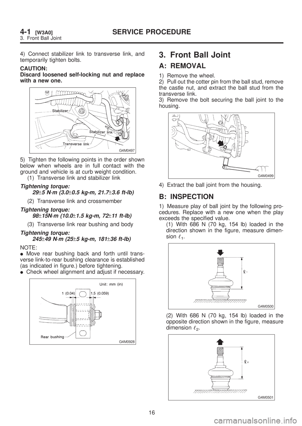
4) Connect stabilizer link to transverse link, and
temporarily tighten bolts.
CAUTION:
Discard loosened self-locking nut and replace
with a new one.
G4M0497
5) Tighten the following points in the order shown
below when wheels are in full contact with the
ground and vehicle is at curb weight condition.
(1) Transverse link and stabilizer link
Tightening torque:
29
±5 N´m (3.0±0.5 kg-m, 21.7±3.6 ft-lb)
(2) Transverse link and crossmember
Tightening torque:
98
±15N´m (10.0±1.5 kg-m, 72±11 ft-lb)
(3) Transverse link rear bushing and body
Tightening torque:
245
±49 N´m (25±5 kg-m, 181±36 ft-lb)
NOTE:
IMove rear bushing back and forth until trans-
verse link-to-rear bushing clearance is established
(as indicated in figure.) before tightening.
ICheck wheel alignment and adjust if necessary.
G4M0928
3. Front Ball Joint
A: REMOVAL
1) Remove the wheel.
2) Pull out the cotter pin from the ball stud, remove
the castle nut, and extract the ball stud from the
transverse link.
3) Remove the bolt securing the ball joint to the
housing.
G4M0499
4) Extract the ball joint from the housing.
B: INSPECTION
1) Measure play of ball joint by the following pro-
cedures. Replace with a new one when the play
exceeds the specified value.
(1) With 686 N (70 kg, 154 lb) loaded in the
direction shown in the figure, measure dimen-
sion
1.
G4M0500
(2) With 686 N (70 kg, 154 lb) loaded in the
opposite direction shown in the figure, measure
dimension
2.
G4M0501
16
4-1[W3A0]SERVICE PROCEDURE
3. Front Ball Joint
Page 719 of 1456
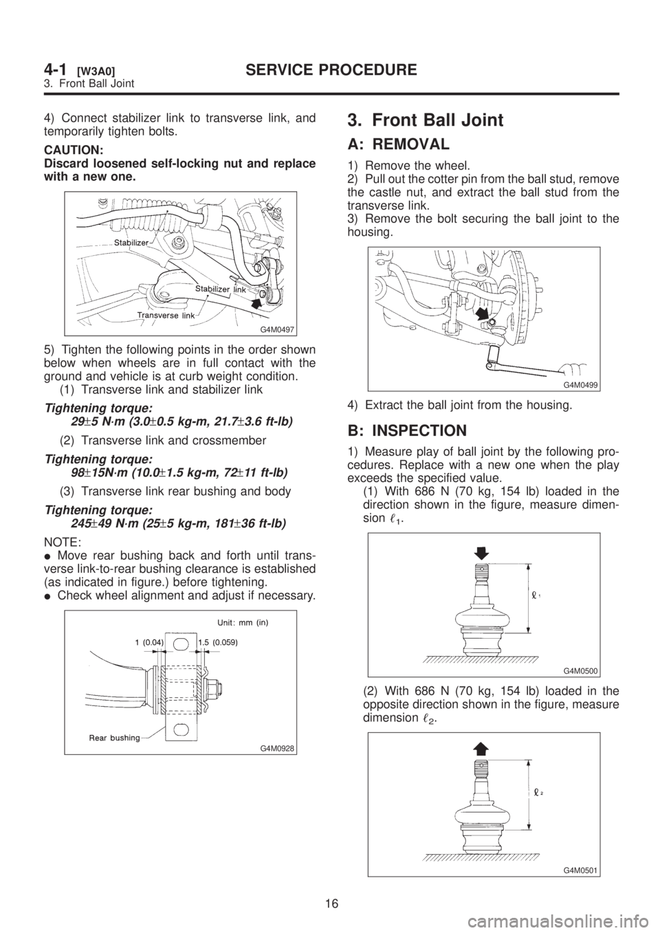
4) Connect stabilizer link to transverse link, and
temporarily tighten bolts.
CAUTION:
Discard loosened self-locking nut and replace
with a new one.
G4M0497
5) Tighten the following points in the order shown
below when wheels are in full contact with the
ground and vehicle is at curb weight condition.
(1) Transverse link and stabilizer link
Tightening torque:
29
±5 N´m (3.0±0.5 kg-m, 21.7±3.6 ft-lb)
(2) Transverse link and crossmember
Tightening torque:
98
±15N´m (10.0±1.5 kg-m, 72±11 ft-lb)
(3) Transverse link rear bushing and body
Tightening torque:
245
±49 N´m (25±5 kg-m, 181±36 ft-lb)
NOTE:
IMove rear bushing back and forth until trans-
verse link-to-rear bushing clearance is established
(as indicated in figure.) before tightening.
ICheck wheel alignment and adjust if necessary.
G4M0928
3. Front Ball Joint
A: REMOVAL
1) Remove the wheel.
2) Pull out the cotter pin from the ball stud, remove
the castle nut, and extract the ball stud from the
transverse link.
3) Remove the bolt securing the ball joint to the
housing.
G4M0499
4) Extract the ball joint from the housing.
B: INSPECTION
1) Measure play of ball joint by the following pro-
cedures. Replace with a new one when the play
exceeds the specified value.
(1) With 686 N (70 kg, 154 lb) loaded in the
direction shown in the figure, measure dimen-
sion
1.
G4M0500
(2) With 686 N (70 kg, 154 lb) loaded in the
opposite direction shown in the figure, measure
dimension
2.
G4M0501
16
4-1[W3A0]SERVICE PROCEDURE
3. Front Ball Joint
Page 1001 of 1456
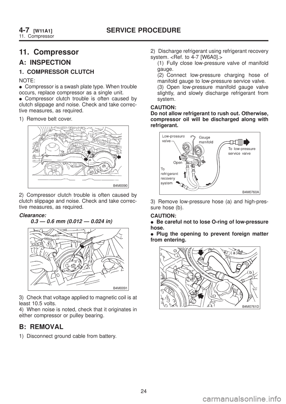
11. Compressor
A: INSPECTION
1. COMPRESSOR CLUTCH
NOTE:
ICompressor is a swash plate type. When trouble
occurs, replace compressor as a single unit.
ICompressor clutch trouble is often caused by
clutch slippage and noise. Check and take correc-
tive measures, as required.
1) Remove belt cover.
B4M0090
2) Compressor clutch trouble is often caused by
clutch slippage and noise. Check and take correc-
tive measures, as required.
Clearance:
0.3 Ð 0.6 mm (0.012 Ð 0.024 in)
B4M0091
3) Check that voltage applied to magnetic coil is at
least 10.5 volts.
4) When noise is noted, check that it originates in
either compressor or pulley bearing.
B: REMOVAL
1) Disconnect ground cable from battery.2) Discharge refrigerant using refrigerant recovery
system.
(1) Fully close low-pressure valve of manifold
gauge.
(2) Connect low-pressure charging hose of
manifold gauge to low-pressure service valve.
(3) Open low-pressure manifold gauge valve
slightly, and slowly discharge refrigerant from
system.
CAUTION:
Do not allow refrigerant to rush out. Otherwise,
compressor oil will be discharged along with
refrigerant.
B4M0760A
3) Remove low-pressure hose (a) and high-pres-
sure hose (b).
CAUTION:
IBe careful not to lose O-ring of low-pressure
hose.
IPlug the opening to prevent foreign matter
from entering.
B4M0761D
24
4-7[W11A1]SERVICE PROCEDURE
11. Compressor
Page 1064 of 1456
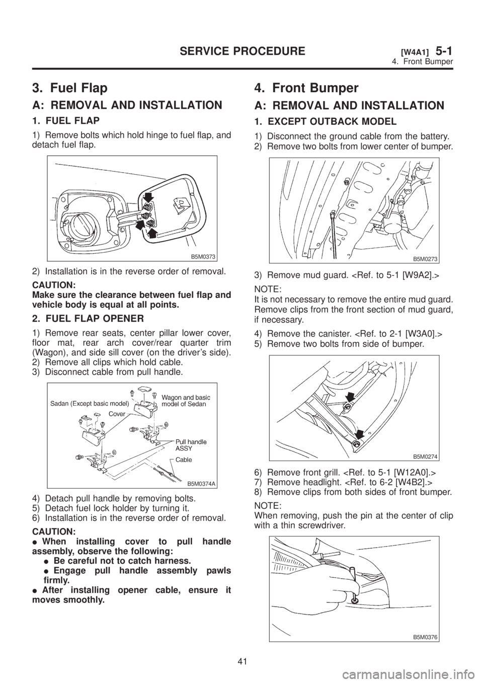
3. Fuel Flap
A: REMOVAL AND INSTALLATION
1. FUEL FLAP
1) Remove bolts which hold hinge to fuel flap, and
detach fuel flap.
B5M0373
2) Installation is in the reverse order of removal.
CAUTION:
Make sure the clearance between fuel flap and
vehicle body is equal at all points.
2. FUEL FLAP OPENER
1) Remove rear seats, center pillar lower cover,
floor mat, rear arch cover/rear quarter trim
(Wagon), and side sill cover (on the driver's side).
2) Remove all clips which hold cable.
3) Disconnect cable from pull handle.
B5M0374A
4) Detach pull handle by removing bolts.
5) Detach fuel lock holder by turning it.
6) Installation is in the reverse order of removal.
CAUTION:
IWhen installing cover to pull handle
assembly, observe the following:
IBe careful not to catch harness.
IEngage pull handle assembly pawls
firmly.
IAfter installing opener cable, ensure it
moves smoothly.
4. Front Bumper
A: REMOVAL AND INSTALLATION
1. EXCEPT OUTBACK MODEL
1) Disconnect the ground cable from the battery.
2) Remove two bolts from lower center of bumper.
B5M0273
3) Remove mud guard.
NOTE:
It is not necessary to remove the entire mud guard.
Remove clips from the front section of mud guard,
if necessary.
4) Remove the canister.
5) Remove two bolts from side of bumper.
B5M0274
6) Remove front grill.
7) Remove headlight.
8) Remove clips from both sides of front bumper.
NOTE:
When removing, push the pin at the center of clip
with a thin screwdriver.
B5M0376
41
[W4A1]5-1SERVICE PROCEDURE
4. Front Bumper
Page 1065 of 1456
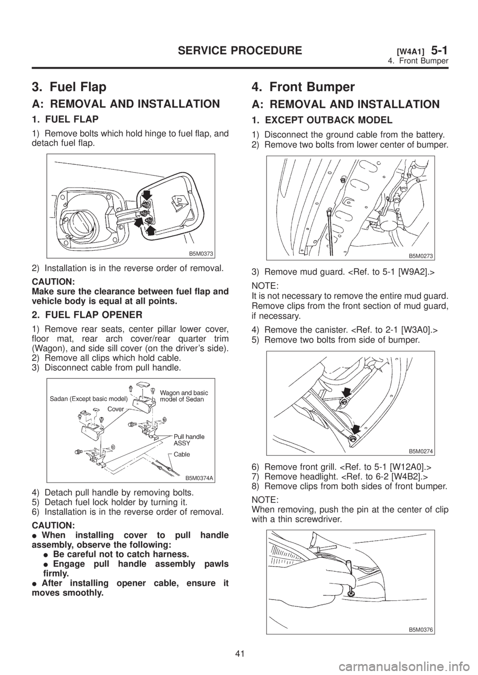
3. Fuel Flap
A: REMOVAL AND INSTALLATION
1. FUEL FLAP
1) Remove bolts which hold hinge to fuel flap, and
detach fuel flap.
B5M0373
2) Installation is in the reverse order of removal.
CAUTION:
Make sure the clearance between fuel flap and
vehicle body is equal at all points.
2. FUEL FLAP OPENER
1) Remove rear seats, center pillar lower cover,
floor mat, rear arch cover/rear quarter trim
(Wagon), and side sill cover (on the driver's side).
2) Remove all clips which hold cable.
3) Disconnect cable from pull handle.
B5M0374A
4) Detach pull handle by removing bolts.
5) Detach fuel lock holder by turning it.
6) Installation is in the reverse order of removal.
CAUTION:
IWhen installing cover to pull handle
assembly, observe the following:
IBe careful not to catch harness.
IEngage pull handle assembly pawls
firmly.
IAfter installing opener cable, ensure it
moves smoothly.
4. Front Bumper
A: REMOVAL AND INSTALLATION
1. EXCEPT OUTBACK MODEL
1) Disconnect the ground cable from the battery.
2) Remove two bolts from lower center of bumper.
B5M0273
3) Remove mud guard.
NOTE:
It is not necessary to remove the entire mud guard.
Remove clips from the front section of mud guard,
if necessary.
4) Remove the canister.
5) Remove two bolts from side of bumper.
B5M0274
6) Remove front grill.
7) Remove headlight.
8) Remove clips from both sides of front bumper.
NOTE:
When removing, push the pin at the center of clip
with a thin screwdriver.
B5M0376
41
[W4A1]5-1SERVICE PROCEDURE
4. Front Bumper