Page 2202 of 2267

Removal Ð Side Air Bag Module
CAUTION:
lBefore servicing SRS, turn the ignition switch ªOFFº,
disconnect both battery cables and wait at least 3 min-
utes.
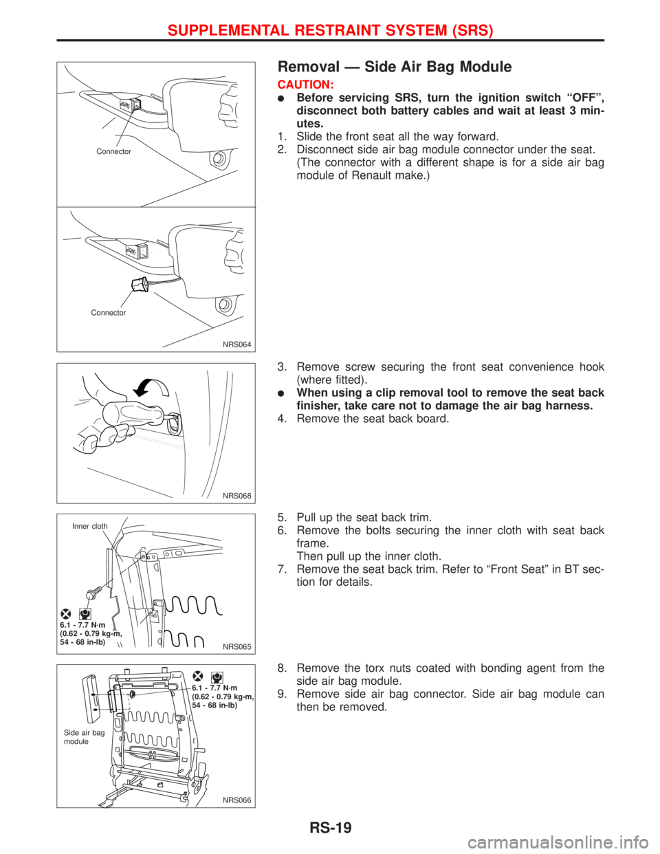
1. Slide the front seat all the way forward.
2. Disconnect side air bag module connector under the seat.
(The connector with a different shape is for a side air bag
module of Renault make.)
3. Remove screw securing the front seat convenience hook
(where fitted).
lWhen using a clip removal tool to remove the seat back
finisher, take care not to damage the air bag harness.
4. Remove the seat back board.
5. Pull up the seat back trim.
6. Remove the bolts securing the inner cloth with seat back
frame.
Then pull up the inner cloth.
7. Remove the seat back trim. Refer to ªFront Seatº in BT sec-
tion for details.
8. Remove the torx nuts coated with bonding agent from the
side air bag module.
9. Remove side air bag connector. Side air bag module can
then be removed.
NRS064 Connector
Connector
NRS068
NRS065 Inner cloth
.6.1 - 7.7 N´m
(0.62 - 0.79 kg-m,
54 - 68 in-lb)
NRS066 Side air bag
module
.6.1 - 7.7 N´m
(0.62 - 0.79 kg-m,
54 - 68 in-lb)
SUPPLEMENTAL RESTRAINT SYSTEM (SRS)
RS-19
Page 2212 of 2267

HOW TO CHANGE SELF-DIAGNOSIS MODE
With CONSULT-II
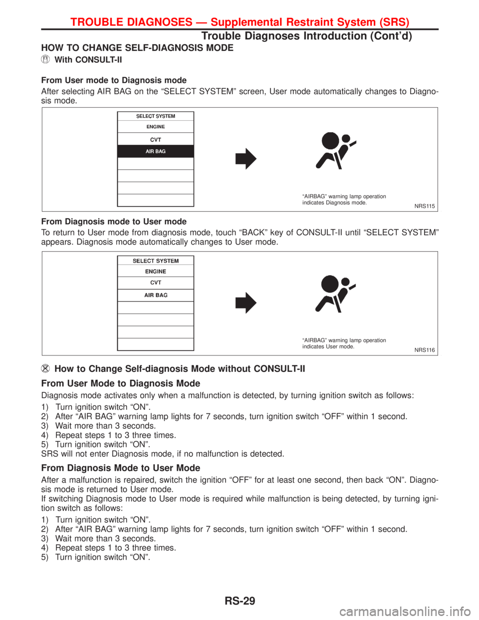
From User mode to Diagnosis mode
After selecting AIR BAG on the ªSELECT SYSTEMº screen, User mode automatically changes to Diagno-
sis mode.
From Diagnosis mode to User mode
To return to User mode from diagnosis mode, touch ªBACKº key of CONSULT-II until ªSELECT SYSTEMº
appears. Diagnosis mode automatically changes to User mode.
How to Change Self-diagnosis Mode without CONSULT-II
From User Mode to Diagnosis Mode
Diagnosis mode activates only when a malfunction is detected, by turning ignition switch as follows:
1) Turn ignition switch ªONº.
2) After ªAIR BAGº warning lamp lights for 7 seconds, turn ignition switch ªOFFº within 1 second.
3) Wait more than 3 seconds.
4) Repeat steps 1 to 3 three times.
5) Turn ignition switch ªONº.
SRS will not enter Diagnosis mode, if no malfunction is detected.
From Diagnosis Mode to User Mode
After a malfunction is repaired, switch the ignition ªOFFº for at least one second, then back ªONº. Diagno-
sis mode is returned to User mode.
If switching Diagnosis mode to User mode is required while malfunction is being detected, by turning igni-
tion switch as follows:
1) Turn ignition switch ªONº.
2) After ªAIR BAGº warning lamp lights for 7 seconds, turn ignition switch ªOFFº within 1 second.
3) Wait more than 3 seconds.
4) Repeat steps 1 to 3 three times.
5) Turn ignition switch ªONº.
NRS115 ªAIRBAGº warning lamp operation
indicates Diagnosis mode.
NRS116 ªAIRBAGº warning lamp operation
indicates User mode.
TROUBLE DIAGNOSES Ð Supplemental Restraint System (SRS)
Trouble Diagnoses Introduction (Cont'd)
RS-29
Page 2213 of 2267
![NISSAN PRIMERA 1999 Electronic Repair Manual HOW TO ERASE SELF-DIAGNOSIS RESULTS
With CONSULT-II
lªSELF-DAIG [CURRENT]º
A current Self-diagnosis result is displayed on the CONSULT-II screen in real time. After the malfunction
is repaired compl NISSAN PRIMERA 1999 Electronic Repair Manual HOW TO ERASE SELF-DIAGNOSIS RESULTS
With CONSULT-II
lªSELF-DAIG [CURRENT]º
A current Self-diagnosis result is displayed on the CONSULT-II screen in real time. After the malfunction
is repaired compl](/manual-img/5/57377/w960_57377-2212.png)
HOW TO ERASE SELF-DIAGNOSIS RESULTS
With CONSULT-II
lªSELF-DAIG [CURRENT]º
A current Self-diagnosis result is displayed on the CONSULT-II screen in real time. After the malfunction
is repaired completely, no malfunction is detected on ªSELF-DIAG [CURRENT]º.
lªSELF-DIAG [PAST]º
Return to the ªSELF-DIAG [CURRENT]º CONSULT-II screen
by pushing ªBACKº key of CONSULT-II and select ªSELF-
DIAG [CURRENT]º in ªSELECT DIAG MODEº. Touch
ªERASEº in ªSELF-DIAG [CURRENT]º mode.
NOTE:
If the memory of the malfunction in ªSELF-DIAG [PAST]º is
not erased, the User mode shows the system malfunction by
the operation of the warning lamp even if the malfunction is
repaired completely.
lªTROUBLE DIAG RECORDº
The memory of ªTROUBLE DIAG RECORDº cannot be erased.
Without CONSULT-II
After a malfunction is repaired, return to User mode from Diagnosis mode by switching the ignition ªOFFº
for at least 1 second, then back ªONº. Diagnosis mode returns to the User mode. At that time, self-diagno-
sis result is cleared.
How to Perform Trouble Diagnoses for Quick
and Accurate Repair
A good understanding of the malfunction conditions can make troubleshooting faster and more accurate. In
general, each customer feels differently about a malfunction. It is important to fully understand the symp-
toms or conditions for a customer complaint.
INFORMATION FROM CUSTOMER
WHAT ....... Vehicle model
WHEN ...... Date, Frequencies
WHERE .... Road conditions
HOW ........ Operating conditions, Symptoms
PRELIMINARY CHECK
Check that the following parts are in good order.
lBattery [Refer to EL section (ªBATTERYº).]
lFuse [Refer to EL section (ªFuseº, ªPOWER SUPPLY ROUTINGº).]
lSystem component-to-harness connections
C2SDC02
TROUBLE DIAGNOSES Ð Supplemental Restraint System (SRS)
Trouble Diagnoses Introduction (Cont'd)
RS-30
Page 2220 of 2267

SRS-Operation Check
DIAGNOSTIC PROCEDURE 1
Checking Air Bag Operation by using ªAIR BAGº Warning
Lamp Ð User mode
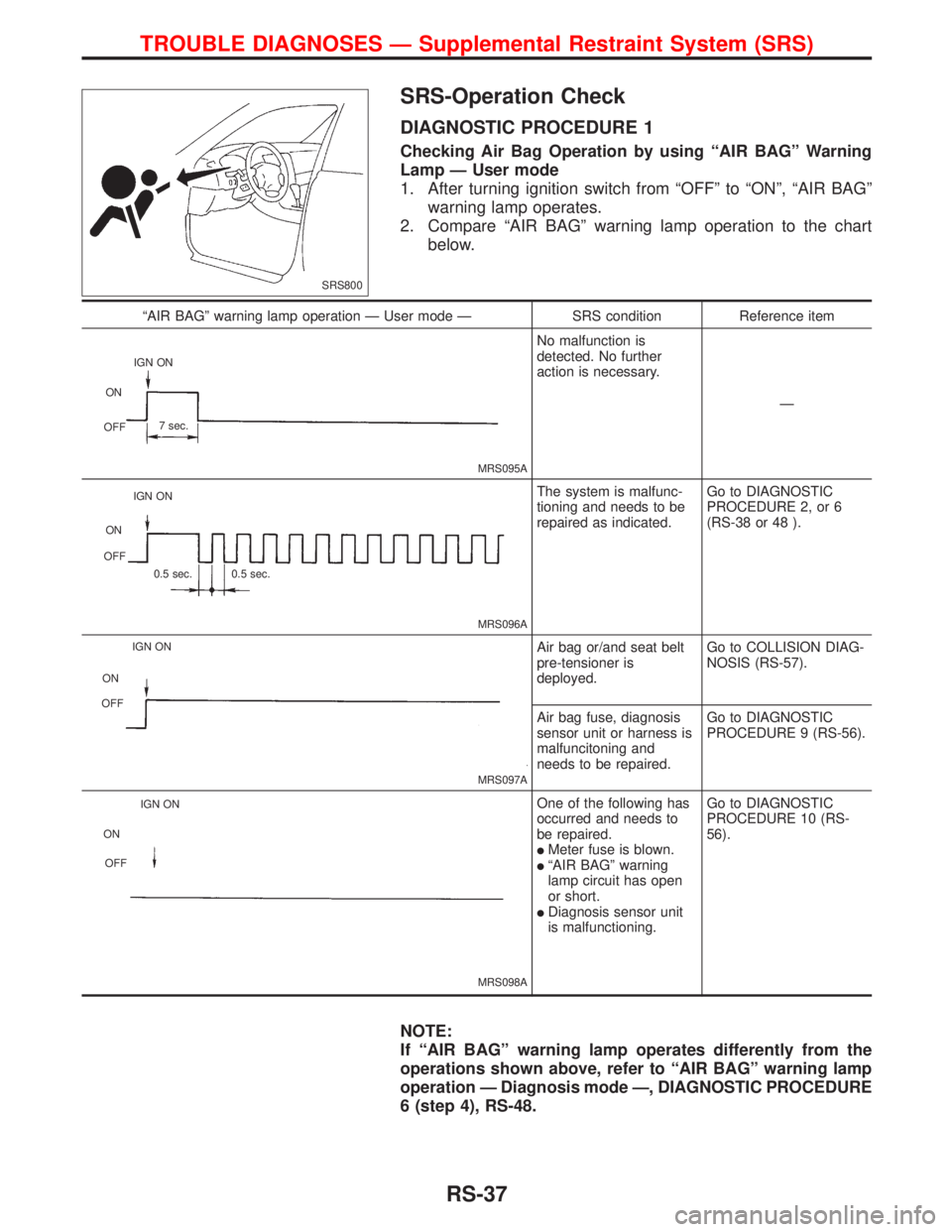
1. After turning ignition switch from ªOFFº to ªONº, ªAIR BAGº
warning lamp operates.
2. Compare ªAIR BAGº warning lamp operation to the chart
below.
NOTE:
If ªAIR BAGº warning lamp operates differently from the
operations shown above, refer to ªAIR BAGº warning lamp
operation Ð Diagnosis mode Ð, DIAGNOSTIC PROCEDURE
6 (step 4), RS-48.
SRS800
ªAIR BAGº warning lamp operation Ð User mode Ð SRS condition Reference item
MRS095A
No malfunction is
detected. No further
action is necessary.
Ð
MRS096A
The system is malfunc-
tioning and needs to be
repaired as indicated.Go to DIAGNOSTIC
PROCEDURE 2, or 6
(RS-38 or 48 ).
MRS097A
Air bag or/and seat belt
pre-tensioner is
deployed.Go to COLLISION DIAG-
NOSIS (RS-57).
Air bag fuse, diagnosis
sensor unit or harness is
malfuncitoning and
needs to be repaired.Go to DIAGNOSTIC
PROCEDURE 9 (RS-56).
MRS098A
One of the following has
occurred and needs to
be repaired.
lMeter fuse is blown.lªAIR BAGº warning
lamp circuit has open
or short.
lDiagnosis sensor unit
is malfunctioning.Go to DIAGNOSTIC
PROCEDURE 10 (RS-
56).
IGN ON
ON
OFF7 sec.
IGN ON
ON
OFF
0.5 sec. 0.5 sec.
IGN ON
ON
OFF
IGN ON
ON
OFF
TROUBLE DIAGNOSES Ð Supplemental Restraint System (SRS)
RS-37
Page 2221 of 2267
Trouble Diagnoses with CONSULT-II
DIAGNOSTIC PROCEDURE 2
Inspecting SRS malfunctioning parts by using CONSULT-II
Ð Diagnosis mode
1. Turn ignition switch to the ªOFFº.
2. Connect ªCONSULT-IIº to Data link connector.
3. Turn ignition switch ªONº.
4. Touch ªSTARTº.
5. Touch ªAIRBAGº.
6. Touch ªSELF-DIAG [CURRENT]º.
7. Diagnostic codes are displayed on ªSELF-DIAG [CUR-
RENT]º.
NRS071 Data link connector
SRS695
C2SSE01
C2SDM02
SRS772
TROUBLE DIAGNOSES Ð Supplemental Restraint System (SRS)
RS-38
Page 2222 of 2267
![NISSAN PRIMERA 1999 Electronic Repair Manual If no malfunction is detected on ªSELF-DIAG [CURRENT]º but
malfunction is indicated by the ªAIR BAGº, warning lamp, go to
DIAGNOSTIC PROCEDURE 4, page RS-43, to diagnose the
following situations:
NISSAN PRIMERA 1999 Electronic Repair Manual If no malfunction is detected on ªSELF-DIAG [CURRENT]º but
malfunction is indicated by the ªAIR BAGº, warning lamp, go to
DIAGNOSTIC PROCEDURE 4, page RS-43, to diagnose the
following situations:](/manual-img/5/57377/w960_57377-2221.png)
If no malfunction is detected on ªSELF-DIAG [CURRENT]º but
malfunction is indicated by the ªAIR BAGº, warning lamp, go to
DIAGNOSTIC PROCEDURE 4, page RS-43, to diagnose the
following situations:
lSelf-diagnostic result ªSELF-DIAG [PAST]º (previously
stored in the memory) might not be erased after repair.
lThe SRS system malfunctions intermittently.
8. Touch ªPRINTº.
9. Compare diagnostic codes to ªCONSULT-II Diagnostic Code
Chartº, page RS-39.
10. Touch ªBACKº key of CONSULT-II until ªSELECT SYSTEM º
appears in order to return to User mode from Diagnosis
mode.
11. Turn ignition switch ªOFFº, then turn off and disconnect CON-
SULT-II and both battery cables.
12. Repair the system as outlined by the ªRepair orderº in ªCON-
SULT-II Diagnostic Code Chartº, that corresponds to the self-
diagnostic result. For replacement procedure of component
parts, refer to RS-13.
13. After repairing the system, go to DIAGNOSTIC PROCE-
DURE 3, page RS-42 for final checking.
CONSULT-II Diagnostic Code Chart
(ªSELF-DIAGNOSISº)
Diagnostic item ExplanationRepair order
Recheck SRS at each
replacement.
NO DTC IS DETECTED. When malfunction is indi-
cated by the ªAIR BAGº
warning lamp in User mode
lLow battery voltage (Less
than 9V).lGo to DIAGNOSTIC PRO-
CEDURE 3 (RS-42) after
charging battery.
lSelf-diagnostic result
ªSELF-DIAG [PAST]º (pre-
viously stored in the
memory) might not be
erased after repair.
lIntermittent malfunction has
been detected in the past.Go to DIAGNOSTIC PROCE-
DURE 4 (RS-43).
No malfunction is detected.
lGo to DIAGNOSTIC PRO-
CEDURE 3 (RS-42).
AIRBAG MODULE
[OPEN]
lDriver's air bag module circuit is open. (including the spiral
cable)1. Visually check the wiring
harness connection.
2. Replace the harness if it
has visible damage.
3. Replace driver's air bag
module.
(Before disposing of it, it
must be deployed.)
4. Replace the spiral cable.
5. Replace the diagnosis
sensor unit.
6. Replace the related har-
ness.
C2SDC02
TROUBLE DIAGNOSES Ð Supplemental Restraint System (SRS)
Trouble Diagnoses with CONSULT-II
(Cont'd)
RS-39
Page 2225 of 2267
DIAGNOSTIC PROCEDURE 3
Final checking after repairing SRS by using CONSULT-II Ð
Diagnosis mode
1. After repairing SRS, connect both battery cables.
2. Connect CONSULT-II to Data link connector.
3. Turn ignition switch from ªOFFº to ªONº.
4. Touch ªSTARTº.
5. Touch ªAIRBAGº.
6. Touch ªSELF-DIAG [CURRENT]º.
7. If no malfunction is detected on ªSELF-DIAG [CURRENT]º,
repair of SRS is completed. Go to step 8.
If any malfunction is displayed on ªSELF-DIAG [CURRENT]º,
the malfunctioning part is not repaired completely or another
malfunctioning part is detected. Go to DIAGNOSTIC PRO-
CEDURE 2, page RS-38, and repair malfunctioning part
completely.
NRS071 Data link connector
SRS695
C2SSE01
C2SDM02
C2SDC02
TROUBLE DIAGNOSES Ð Supplemental Restraint System (SRS)
Trouble Diagnoses with CONSULT-II
(Cont'd)
RS-42
Page 2226 of 2267
![NISSAN PRIMERA 1999 Electronic Repair Manual 8. Touch ªERASEº.
NOTE:
Touch ªERASEº to clear the memory of the malfunction
(ªSELF-DIAG [PAST]º).
If the memory of the malfunction in ªSELF-DIAG [PAST] is not
erased, the User mode shows the s NISSAN PRIMERA 1999 Electronic Repair Manual 8. Touch ªERASEº.
NOTE:
Touch ªERASEº to clear the memory of the malfunction
(ªSELF-DIAG [PAST]º).
If the memory of the malfunction in ªSELF-DIAG [PAST] is not
erased, the User mode shows the s](/manual-img/5/57377/w960_57377-2225.png)
8. Touch ªERASEº.
NOTE:
Touch ªERASEº to clear the memory of the malfunction
(ªSELF-DIAG [PAST]º).
If the memory of the malfunction in ªSELF-DIAG [PAST] is not
erased, the User mode shows the system malfunction by the
operation of the warning lamp even if the malfunction is repaired
completely.
9. Touch ªBACKº key of CONSULT-II to ªSELECT SYSTEMº
screen. Touch ªSELF-DIAG [PAST]º.
10. Check that no malfunction is detected on ªSELF-DIAG
[PAST]º.
11. Touch ªBACKº key of CONSULT-II until ªSELECT SYSTEMº
appears in order to return to User mode from Diagnosis
mode.
12. Turn ignition switch ªOFFº then turn off and disconnect CON-
SULT-II.
13. Go to ªSRS Operation Checkº, page RS-37 to check SRS
operation by using ªAIR BAGº warning lamp with User mode.
DIAGNOSTIC PROCEDURE 4 (CONTINUED FROM
DIAGNOSTIC PROCEDURE 2)
Inspecting SRS malfunctioning record
Is it the first time for maintenance of SRS?
Ye s
ENo
Self-diagnostic results
ªSELF-DIAG [PAST]º (previ-
ously stored in the memory)
might not be erased after
repair. Go to DIAGNOSTIC
PROCEDURE 3, step 8
(RS-42).
Go to DIAGNOSTIC PROCEDURE 5
(RS-44).
C2SDC01
C2SDM02
C2SDP02
H
TROUBLE DIAGNOSES Ð Supplemental Restraint System (SRS)
Trouble Diagnoses with CONSULT-II
(Cont'd)
RS-43