Page 2042 of 2267
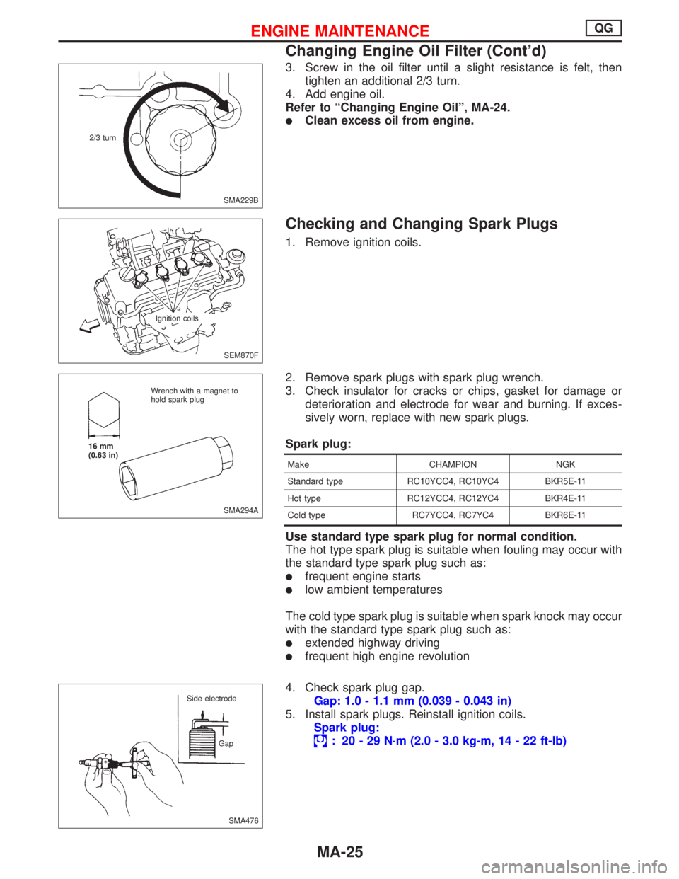
3. Screw in the oil filter until a slight resistance is felt, then
tighten an additional 2/3 turn.
4. Add engine oil.
Refer to“Changing Engine Oil”, MA-24.
�Clean excess oil from engine.
Checking and Changing Spark Plugs
1. Remove ignition coils.
2. Remove spark plugs with spark plug wrench.
3. Check insulator for cracks or chips, gasket for damage or
deterioration and electrode for wear and burning. If exces-
sively worn, replace with new spark plugs.
Spark plug:
Make CHAMPION NGK
Standard type RC10YCC4, RC10YC4 BKR5E-11
Hot type RC12YCC4, RC12YC4 BKR4E-11
Cold type RC7YCC4, RC7YC4 BKR6E-11
Use standard type spark plug for normal condition.
The hot type spark plug is suitable when fouling may occur with
the standard type spark plug such as:
�frequent engine starts
�low ambient temperatures
The cold type spark plug is suitable when spark knock may occur
with the standard type spark plug such as:
�extended highway driving
�frequent high engine revolution
4. Check spark plug gap.
Gap: 1.0 - 1.1 mm (0.039 - 0.043 in)
5. Install spark plugs. Reinstall ignition coils.
Spark plug:
: 20-29N·m (2.0 - 3.0 kg-m, 14 - 22 ft-lb)
SMA229B 2/3 turn
SEM870F
.Ignition coils
SMA294A Wrench with a magnet to
hold spark plug
16 mm
(0.63 in)
SMA476 Side electrode
Gap
ENGINE MAINTENANCEQG
Changing Engine Oil Filter (Cont’d)
MA-25
Page 2044 of 2267
Checking Front Heated Oxygen Sensor
(HO2S)
Checking procedure
INSPECTION START
Start engine and warm it up until water temperature indicator points to the
middle of gauge.
1. See“M/R F/C MNT”in“Data monitor”mode.
2. Run engine at about 2,000 rpm for about 2 minutes under no-
load.
3. Maintaining engine at 2,000 rpm under no-load (engine is
warmed up sufficiently.), check that the monitor fluctuates
between“LEAN”and“RICH”more than 5 times during 10 sec-
onds.
1 time RICH→LEAN→RICH
2 times RICH→LEAN→RICH→LEAN→RICH ...
OK NG
INSPECTION END
Check and adjustment should be made by
referring to IDLE SPEED/IGNITION TIMING/
IDLE MIXTURE RATIO INSPECTION (BASIC
SERVICE PROCEDURE) in EC section.
C2DMM06
NEF125A Data link connector.NEF125A Fuse box
SEF051PA Malfunction indicator lamp
�
�
��
ENGINE MAINTENANCEQG
MA-27
Page 2046 of 2267
Changing Engine Coolant
WARNING:
To avoid being scalded, never change the coolant when the
engine is hot.
Heater
—DRAINING ENGINE COOLANT—
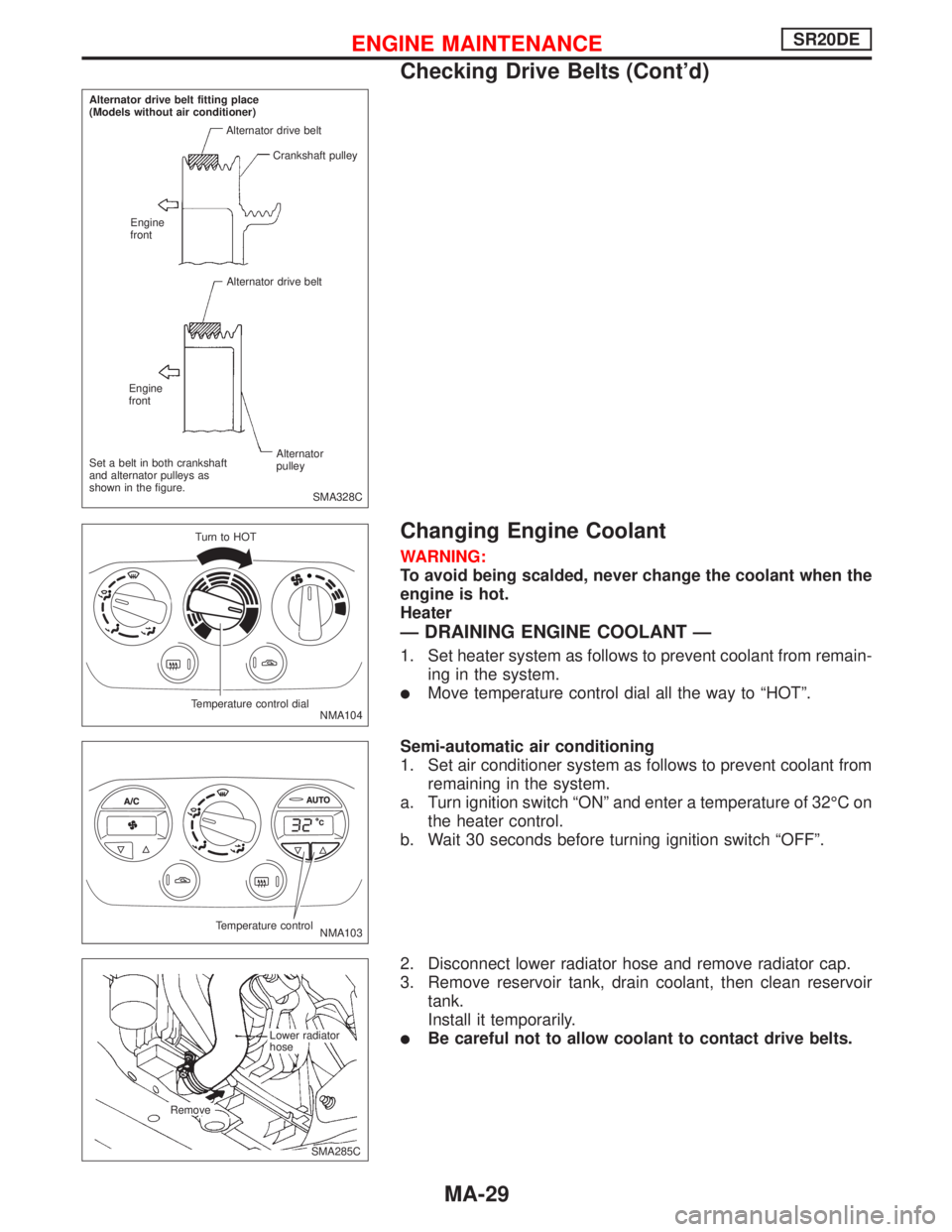
1. Set heater system as follows to prevent coolant from remain-
ing in the system.
�Move temperature control dial all the way to“HOT”.
Semi-automatic air conditioning
1. Set air conditioner system as follows to prevent coolant from
remaining in the system.
a. Turn ignition switch“ON”and enter a temperature of 32°Con
the heater control.
b. Wait 30 seconds before turning ignition switch“OFF”.
2. Disconnect lower radiator hose and remove radiator cap.
3. Remove reservoir tank, drain coolant, then clean reservoir
tank.
Install it temporarily.
�Be careful not to allow coolant to contact drive belts.
SMA328C Alternator drive belt fitting place
(Models without air conditioner)
Alternator drive belt
Crankshaft pulley
Engine
front
Alternator drive belt
Engine
front
Alternator
pulley Set a belt in both crankshaft
and alternator pulleys as
shown in the figure.
NMA104 Turn to HOT
Temperature control dial
NMA103 Temperature control
.SMA285C Lower radiator
hose
Remove
ENGINE MAINTENANCESR20DE
Checking Drive Belts (Cont’d)
MA-29
Page 2050 of 2267
Checking Fuel Lines
Inspect fuel lines and tank for improper attachment and for leaks,
cracks, damage, loose connections, chafing and deterioration.
If necessary, repair or replace faulty parts.
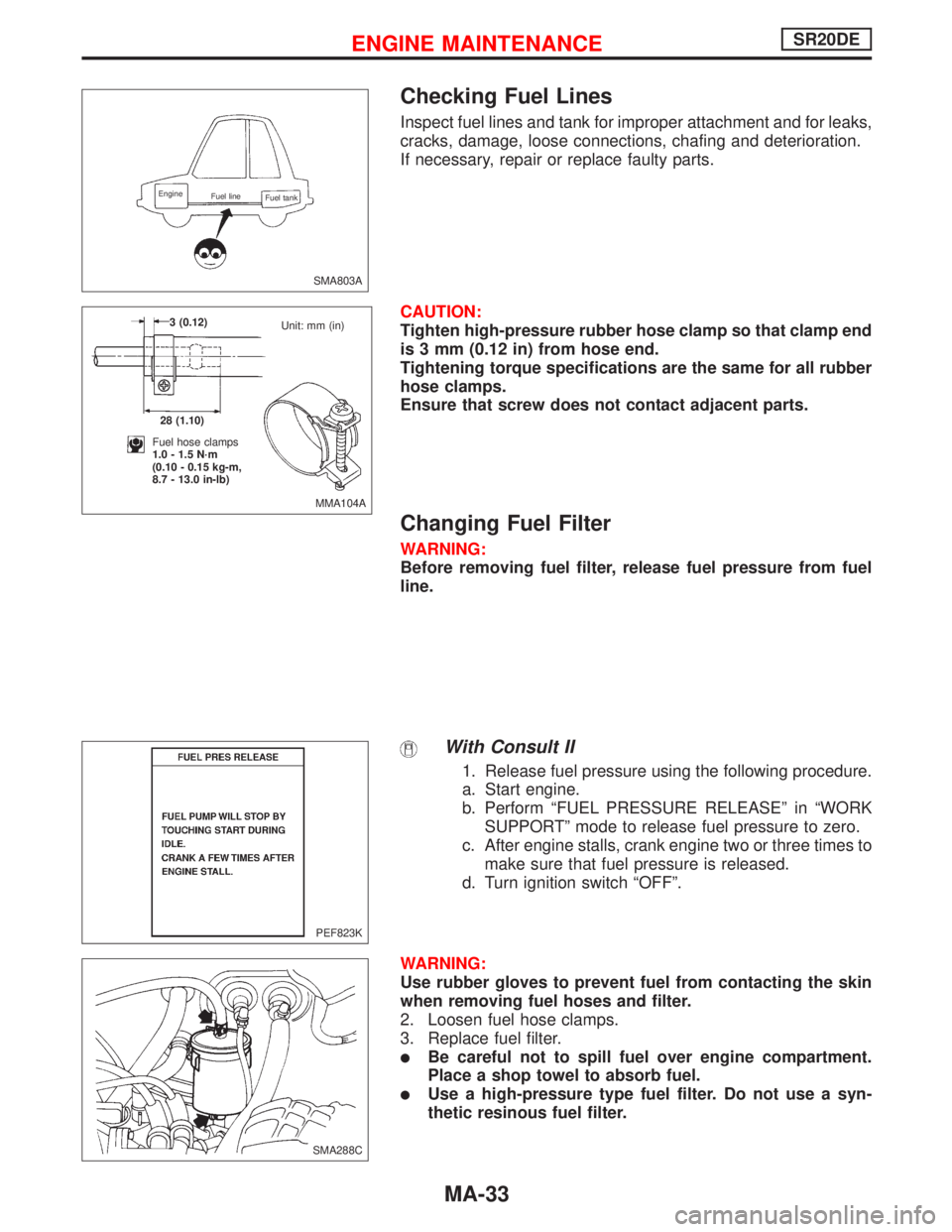
CAUTION:
Tighten high-pressure rubber hose clamp so that clamp end
is 3 mm (0.12 in) from hose end.
Tightening torque specifications are the same for all rubber
hose clamps.
Ensure that screw does not contact adjacent parts.
Changing Fuel Filter
WARNING:
Before removing fuel filter, release fuel pressure from fuel
line.
With Consult II
1. Release fuel pressure using the following procedure.
a. Start engine.
b. Perform“FUEL PRESSURE RELEASE”in“WORK
SUPPORT”mode to release fuel pressure to zero.
c. After engine stalls, crank engine two or three times to
make sure that fuel pressure is released.
d. Turn ignition switch“OFF”.
WARNING:
Use rubber gloves to prevent fuel from contacting the skin
when removing fuel hoses and filter.
2. Loosen fuel hose clamps.
3. Replace fuel filter.
�Be careful not to spill fuel over engine compartment.
Place a shop towel to absorb fuel.
�Use a high-pressure type fuel filter. Do not use a syn-
thetic resinous fuel filter.
SMA803A
Engine
Fuel line
Fuel tank
MMA104A 3 (0.12)
28 (1.10)
Fuel hose clamps
1.0 - 1.5 N·m
(0.10 - 0.15 kg-m,
8.7 - 13.0 in-lb)Unit: mm (in)
PEF823K
.SMA288C
ENGINE MAINTENANCESR20DE
MA-33
Page 2052 of 2267
Changing Engine Oil Filter
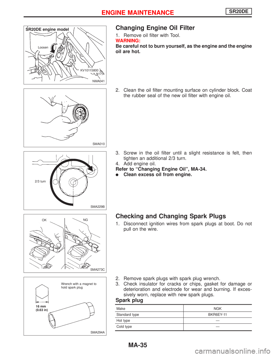
1. Remove oil filter with Tool.
WARNING:
Be careful not to burn yourself, as the engine and the engine
oil are hot.
2. Clean the oil filter mounting surface on cylinder block. Coat
the rubber seal of the new oil filter with engine oil.
3. Screw in the oil filter until a slight resistance is felt, then
tighten an additional 2/3 turn.
4. Add engine oil.
Refer to“Changing Engine Oil”, MA-34.
�Clean excess oil from engine.
Checking and Changing Spark Plugs
1. Disconnect ignition wires from spark plugs at boot. Do not
pull on the wire.
2. Remove spark plugs with spark plug wrench.
3. Check insulator for cracks or chips, gasket for damage or
deterioration and electrode for wear and burning. If exces-
sively worn, replace with new spark plugs.
Spark plug
Make NGK
Standard type BKR6EY-11
Hot type—
Cold type—
NMA041 Loosen
.KV10115800
.SR20DE engine model
SMA010
SMA229B 2/3 turn
SMA273C OKNG
SMA294A Wrench with a magnet to
hold spark plug
16 mm
(0.63 in)
ENGINE MAINTENANCESR20DE
MA-35
Page 2053 of 2267
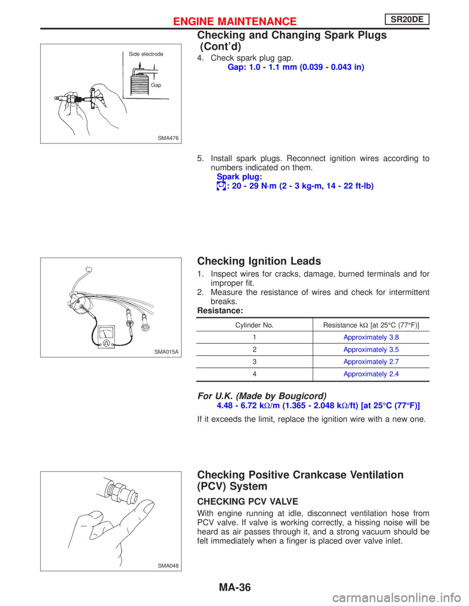
4. Check spark plug gap.
Gap: 1.0 - 1.1 mm (0.039 - 0.043 in)
5. Install spark plugs. Reconnect ignition wires according to
numbers indicated on them.
Spark plug:
:20-29N·m (2 - 3 kg-m, 14 - 22 ft-lb)
Checking Ignition Leads
1. Inspect wires for cracks, damage, burned terminals and for
improper fit.
2. Measure the resistance of wires and check for intermittent
breaks.
Resistance:
Cylinder No. Resistance kΩ[at 25°C (77°F)]
1Approximately 3.8
2Approximately 3.5
3Approximately 2.7
4Approximately 2.4
For U.K. (Made by Bougicord)
4.48 - 6.72 kΩ/m (1.365 - 2.048 kΩ/ft) [at 25°C (77°F)]
If it exceeds the limit, replace the ignition wire with a new one.
Checking Positive Crankcase Ventilation
(PCV) System
CHECKING PCV VALVE
With engine running at idle, disconnect ventilation hose from
PCV valve. If valve is working correctly, a hissing noise will be
heard as air passes through it, and a strong vacuum should be
felt immediately when a finger is placed over valve inlet.
SMA476 Side electrode
Gap
SMA015A
SMA048
ENGINE MAINTENANCESR20DE
Checking and Changing Spark Plugs
(Cont’d)
MA-36
Page 2055 of 2267
Checking Front Heated Oxygen Sensor
(HO2S)
Checking procedure
INSPECTION START
Start engine and warm up until water temperature indicator points to the
middle of gauge.
1. See“M/R F/C MNT”in“Data monitor”mode.
2. Run engine at about 2,000 rpm for about 2 minutes under no-
load.
3. Maintaining engine at 2,000 rpm under no-load (engine is
warmed up sufficiently.), check that the monitor fluctuates
between“LEAN”and“RICH”more than 5 times during 10 sec-
onds.
1 time RICH→LEAN→RICH
2 times RICH→LEAN→RICH→LEAN→RICH ...
OK NG
INSPECTION END
Check and adjustment should be made by
referring to IDLE SPEED/IGNITION TIMING/
IDLE MIXTURE RATIO INSPECTION (BASIC
SERVICE PROCEDURE) in EC section.
PEF054P
NEF125A Data link connector.NEF125A Fuse box
SEF051PA Malfunction indicator lamp
�
�
��
ENGINE MAINTENANCESR20DE
MA-38
Page 2057 of 2267
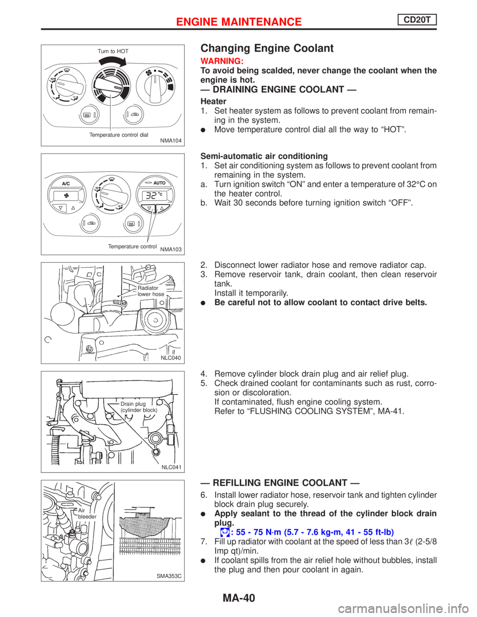
Changing Engine Coolant
WARNING:
To avoid being scalded, never change the coolant when the
engine is hot.
—DRAINING ENGINE COOLANT—
Heater
1. Set heater system as follows to prevent coolant from remain-
ing in the system.
�Move temperature control dial all the way to“HOT”.
Semi-automatic air conditioning
1. Set air conditioning system as follows to prevent coolant from
remaining in the system.
a. Turn ignition switch“ON”and enter a temperature of 32°Con
the heater control.
b. Wait 30 seconds before turning ignition switch“OFF”.
2. Disconnect lower radiator hose and remove radiator cap.
3. Remove reservoir tank, drain coolant, then clean reservoir
tank.
Install it temporarily.
�Be careful not to allow coolant to contact drive belts.
4. Remove cylinder block drain plug and air relief plug.
5. Check drained coolant for contaminants such as rust, corro-
sion or discoloration.
If contaminated, flush engine cooling system.
Refer to“FLUSHING COOLING SYSTEM”, MA-41.
—REFILLING ENGINE COOLANT—
6. Install lower radiator hose, reservoir tank and tighten cylinder
block drain plug securely.
�Apply sealant to the thread of the cylinder block drain
plug.
:55-75N·m (5.7 - 7.6 kg-m, 41 - 55 ft-lb)
7. Fill up radiator with coolant at the speed of less than 3�(2-5/8
Imp qt)/min.
�If coolant spills from the air relief hole without bubbles, install
the plug and then pour coolant in again.
NMA104 Turn to HOT
Temperature control dial
NMA103 Temperature control
.NLC040
.Radiator
lower hose
NLC041 Drain plug
(cylinder block)
SMA353C Air
bleeder
ENGINE MAINTENANCECD20T
MA-40