Page 1498 of 2267
Passenger Compartment
LHD MODELS
YEL235C Time control unit
Blower
relay
Circuit
breaker-1Indicator control unit
Stop lamp switchNATS IMMU
Auto level control unit
Headlamp washer timer
Ignition
relay
Circuit breaker-2
Theft warning horn relay
Fuse block (J/B)
Rear window defogger relayAir bag diagnosis sensor unit
TCM (Transmission control module)Daytime light control unit
Fuse block (J/B)
Time control unt
Power window relay
Front fog lamp relay
Fuel pump relayA/C LOW relay, A/C MED-LOW relay, A/C MED-HIGH relay, A/C HIGH relayECM
LOCATION OF ELECTRICAL UNITS
EL-366
Page 1815 of 2267

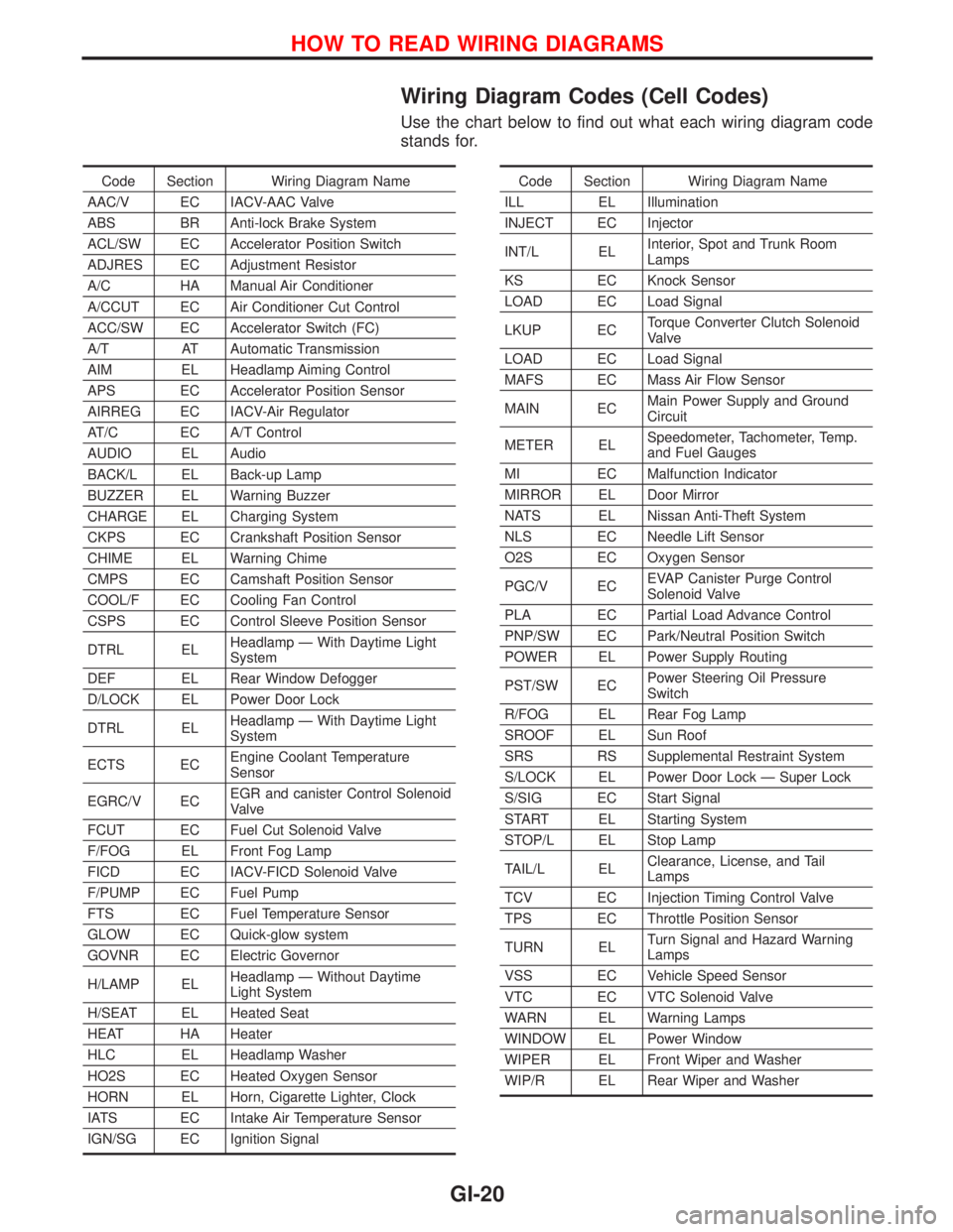
Wiring Diagram Codes (Cell Codes)
Use the chart below to find out what each wiring diagram code
stands for.
Code Section Wiring Diagram Name
AAC/V EC IACV-AAC Valve
ABS BR Anti-lock Brake System
ACL/SW EC Accelerator Position Switch
ADJRES EC Adjustment Resistor
A/C HA Manual Air Conditioner
A/CCUT EC Air Conditioner Cut Control
ACC/SW EC Accelerator Switch (FC)
A/T AT Automatic Transmission
AIM EL Headlamp Aiming Control
APS EC Accelerator Position Sensor
AIRREG EC IACV-Air Regulator
AT/C EC A/T Control
AUDIO EL Audio
BACK/L EL Back-up Lamp
BUZZER EL Warning Buzzer
CHARGE EL Charging System
CKPS EC Crankshaft Position Sensor
CHIME EL Warning Chime
CMPS EC Camshaft Position Sensor
COOL/F EC Cooling Fan Control
CSPS EC Control Sleeve Position Sensor
DTRL ELHeadlamp Ð With Daytime Light
System
DEF EL Rear Window Defogger
D/LOCK EL Power Door Lock
DTRL ELHeadlamp Ð With Daytime Light
System
ECTS ECEngine Coolant Temperature
Sensor
EGRC/V ECEGR and canister Control Solenoid
Valve
FCUT EC Fuel Cut Solenoid Valve
F/FOG EL Front Fog Lamp
FICD EC IACV-FICD Solenoid Valve
F/PUMP EC Fuel Pump
FTS EC Fuel Temperature Sensor
GLOW EC Quick-glow system
GOVNR EC Electric Governor
H/LAMP ELHeadlamp Ð Without Daytime
Light System
H/SEAT EL Heated Seat
HEAT HA Heater
HLC EL Headlamp Washer
HO2S EC Heated Oxygen Sensor
HORN EL Horn, Cigarette Lighter, Clock
IATS EC Intake Air Temperature Sensor
IGN/SG EC Ignition SignalCode Section Wiring Diagram Name
ILL EL Illumination
INJECT EC Injector
INT/L ELInterior, Spot and Trunk Room
Lamps
KS EC Knock Sensor
LOAD EC Load Signal
LKUP ECTorque Converter Clutch Solenoid
Valve
LOAD EC Load Signal
MAFS EC Mass Air Flow Sensor
MAIN ECMain Power Supply and Ground
Circuit
METER ELSpeedometer, Tachometer, Temp.
and Fuel Gauges
MI EC Malfunction Indicator
MIRROR EL Door Mirror
NATS EL Nissan Anti-Theft System
NLS EC Needle Lift Sensor
O2S EC Oxygen Sensor
PGC/V ECEVAP Canister Purge Control
Solenoid Valve
PLA EC Partial Load Advance Control
PNP/SW EC Park/Neutral Position Switch
POWER EL Power Supply Routing
PST/SW ECPower Steering Oil Pressure
Switch
R/FOG EL Rear Fog Lamp
SROOF EL Sun Roof
SRS RS Supplemental Restraint System
S/LOCK EL Power Door Lock Ð Super Lock
S/SIG EC Start Signal
START EL Starting System
STOP/L EL Stop Lamp
TAIL/L ELClearance, License, and Tail
Lamps
TCV EC Injection Timing Control Valve
TPS EC Throttle Position Sensor
TURN ELTurn Signal and Hazard Warning
Lamps
VSS EC Vehicle Speed Sensor
VTC EC VTC Solenoid Valve
WARN EL Warning Lamps
WINDOW EL Power Window
WIPER EL Front Wiper and Washer
WIP/R EL Rear Wiper and Washer
HOW TO READ WIRING DIAGRAMS
GI-20
Page 1823 of 2267

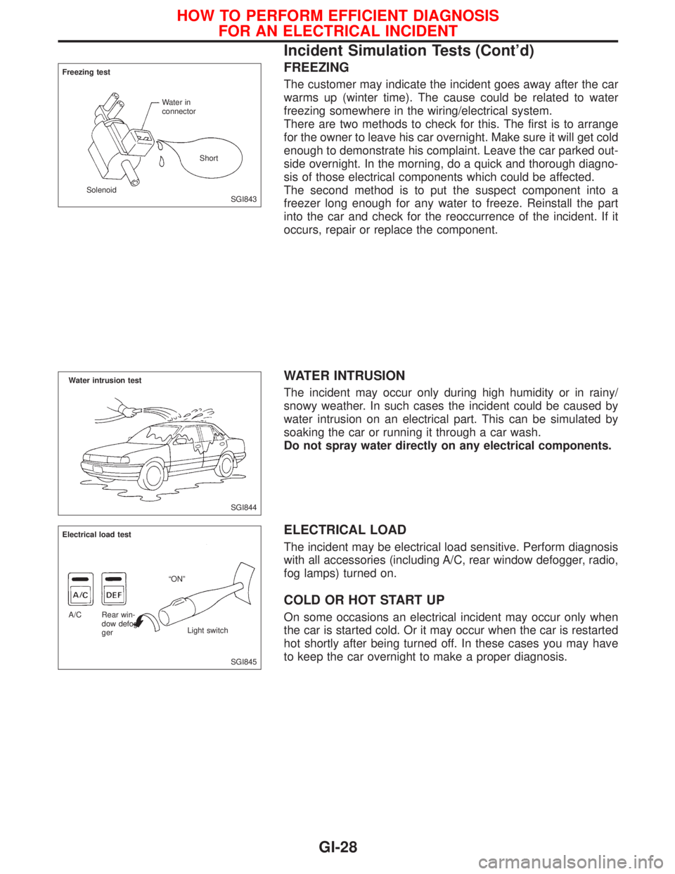
FREEZING
The customer may indicate the incident goes away after the car
warms up (winter time). The cause could be related to water
freezing somewhere in the wiring/electrical system.
There are two methods to check for this. The first is to arrange
for the owner to leave his car overnight. Make sure it will get cold
enough to demonstrate his complaint. Leave the car parked out-
side overnight. In the morning, do a quick and thorough diagno-
sis of those electrical components which could be affected.
The second method is to put the suspect component into a
freezer long enough for any water to freeze. Reinstall the part
into the car and check for the reoccurrence of the incident. If it
occurs, repair or replace the component.
WATER INTRUSION
The incident may occur only during high humidity or in rainy/
snowy weather. In such cases the incident could be caused by
water intrusion on an electrical part. This can be simulated by
soaking the car or running it through a car wash.
Do not spray water directly on any electrical components.
ELECTRICAL LOAD
The incident may be electrical load sensitive. Perform diagnosis
with all accessories (including A/C, rear window defogger, radio,
fog lamps) turned on.
COLD OR HOT START UP
On some occasions an electrical incident may occur only when
the car is started cold. Or it may occur when the car is restarted
hot shortly after being turned off. In these cases you may have
to keep the car overnight to make a proper diagnosis.
SGI843 Freezing test
Water in
connector
SolenoidShort
SGI844
Water intrusion test
SGI845 Electrical load test
ªONº
Rear win-
dow defog-
gerLight switch A/C
HOW TO PERFORM EFFICIENT DIAGNOSIS
FOR AN ELECTRICAL INCIDENT
Incident Simulation Tests (Cont'd)
GI-28