1999 NISSAN PRIMERA fuel filter
[x] Cancel search: fuel filterPage 1118 of 2267
Diagnostic ProcedureNCEC0448
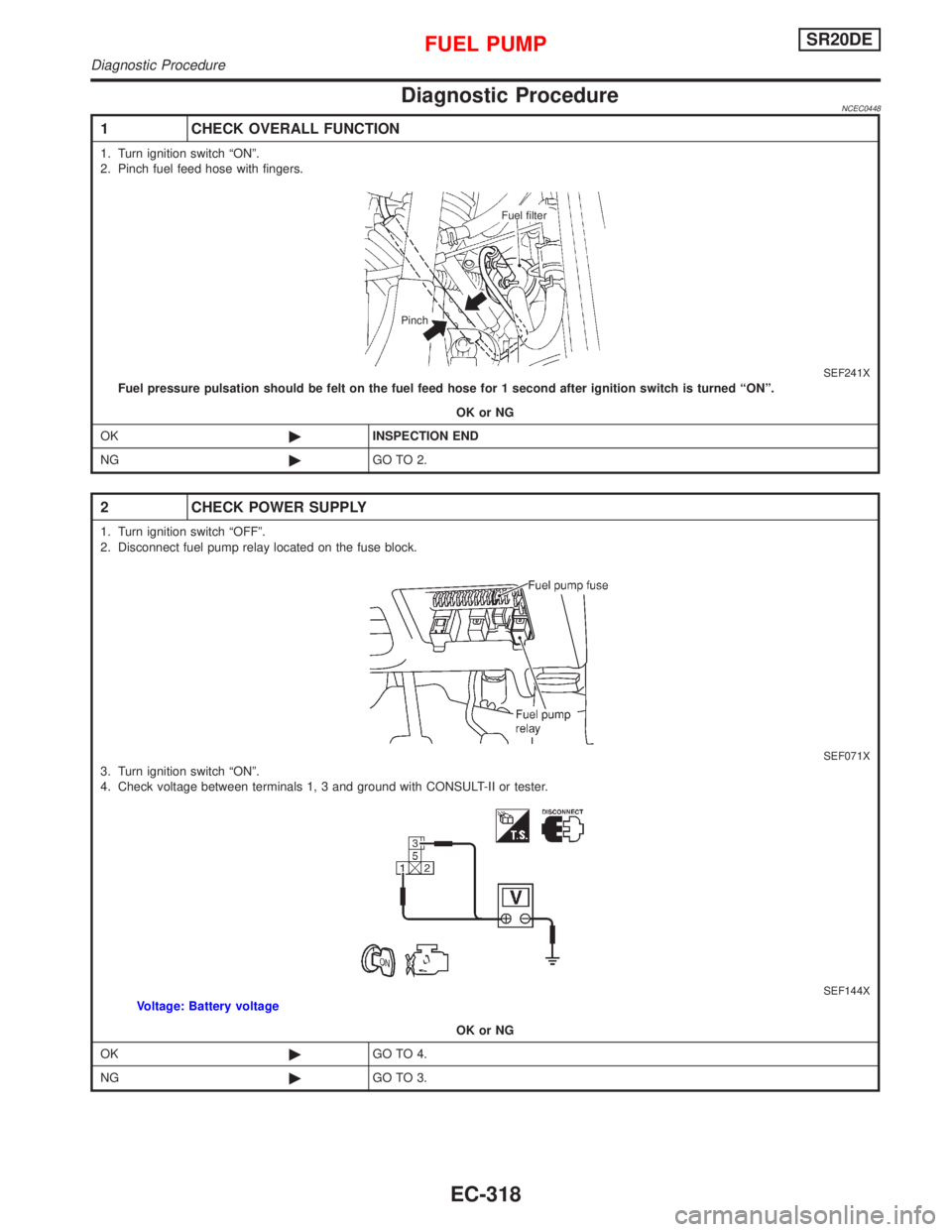
1 CHECK OVERALL FUNCTION
1. Turn ignition switch ªONº.
2. Pinch fuel feed hose with fingers.
SEF241XFuel pressure pulsation should be felt on the fuel feed hose for 1 second after ignition switch is turned ªONº.
OK or NG
OK©INSPECTION END
NG©GO TO 2.
2 CHECK POWER SUPPLY
1. Turn ignition switch ªOFFº.
2. Disconnect fuel pump relay located on the fuse block.
SEF071X3. Turn ignition switch ªONº.
4. Check voltage between terminals 1, 3 and ground with CONSULT-II or tester.
SEF144XVoltage: Battery voltage
OK or NG
OK©GO TO 4.
NG©GO TO 3.
Fuel filter
Pinch
FUEL PUMPSR20DE
Diagnostic Procedure
EC-318
Page 1802 of 2267
lWear protective clothing, including impervious gloves where
practicable.
lDo not put oily rags in pockets.
lAvoid contaminating clothes, particularly underpants, with oil.
lHeavily soiled clothing and oil-impregnated footwear should
not be worn. Overalls must be cleaned regularly.
lFirst Aid treatment should be obtained immediately for open
cuts and wounds.
lUse barrier creams, applying them before each work period,
to help the removal of oil from the skin.
lWash with soap and water to ensure all oil is removed (skin
cleansers and nail brushes will help). Preparations contain-
ing lanolin replace the natural skin oils which have been
removed.
lDo not use gasoline, kerosine, diesel fuel, gas oil, thinners
or solvents for cleaning skin.
lIf skin disorders develop, obtain medical advice without
delay.
lWhere practicable, degrease components prior to handling.
lWhere there is a risk of eye contact, eye protection should
be worn, for example, chemical goggles or face shields; in
addition an eye wash facility should be provided.
ENVIRONMENTAL PROTECTION PRECAUTIONS
Burning used engine oil in small space heaters or boilers can be
recommended only for units of approved design. The heating
system must meet the requirements of HM Inspectorate of Pol-
lution for small burners of less than 0.4 MW. If in doubt check
with the appropriate local authority and/or manufacturer of the
approved appliance.
Dispose of used oil and used oil filters through authorized waste
disposal contractors to licensed waste disposal sites, or to the
waste oil reclamation trade. If in doubt, contact the local author-
ity for advice on disposal facilities.
It is illegal to pour used oil on to the ground, down sewers or
drains, or into water courses.
The regulations concerning the pollution of the environment
will vary between regions.
Precautions for Fuel
GASOLINE ENGINE:
Unleaded gasoline of at least 95 octane (RON)
CAUTION:
Do not use leaded gasoline. Using leaded gasoline will dam-
age the catalytic converter.
DIESEL ENGINE*:
Diesel fuel of at least 50 cetane
* If two types of diesel fuel are available, use summer or win-
ter fuel properly according to the following temperature con-
ditions.
lAbove þ7ÉC (20ÉF) ... Summer type diesel fuel.
lBelow þ7ÉC (20ÉF) ... Winter type diesel fuel.
PRECAUTIONS
Precautions for Engine Oils (Cont'd)
GI-7
Page 1970 of 2267
Combination meter removal and instal-
lation - See Instrument panel ......................BT-15
Combination switch .........................................EL-64
Combustion chamber replacement ..............EM-146
Component location (cool box) ......................HA-39
Compression pressure ..........EM-69, 126, 188, 196
Compressor clutch removal and
installation .................................................HA-111
Compressor mounting ..................................HA-109
Compressor precaution ....................................HA-7
Compressor special service tool ......................HA-7
Connecting rod......EM-55, 171, 176, 186, 193, 200
Connecting rod bearing
clearance....EM-58, 111, 115, 170, 187, 195, 201
Connecting rod bushing clearance ........EM-59, 116
Console box - See Instrument panel ..............BT-15
CONSULT for ABS .........................................BR-69
CONSULT for engine ...........EC-QG-55, EC-SR-68,
EC-CD-27
CONSULT-II general information .....................GI-39
Control sleeve position sensor ................EC-CD-74
Converter housing installation .......................AT-117
COOL/F - Wiring diagram ....................EC-QG-292,
EC-SR-282, EC-CD-89
Coolant replacement .........................MA-19, 29, 40
Cooling circuit (engine) ........................LC-8, 21, 31
Cooling fan control ...........EC-QG-289, EC-SR-279,
EC-CD-20, 87
Cooling fan motor .............EC-QG-299, EC-SR-289
Cooling fan relay ..............EC-QG-299, EC-SR-289,
EC-CD-96
Crank angle sensor built into distributor
- See Camshaft position sensor .......EC-QG-238,
EC-SR-239
‘‘Crankcase emission control system -
See positive crankcase
ventilation’’ .........................EC-QG-28, EC-SR-30
Crankcase ventilation system - See
Positive crankcase
ventilation ..........................EC-QG-28, EC-SR-30
Crankshaft ........EM-53, 57, 61, 110, 113, 118, 131,
138, 139, 167, 172, 175, 186, 194, 200
Crankshaft position sensor (OBD) .......EC-QG-232,
EC-SR-234, 290
Crankshaft position sensor (POS).........EC-QG-232
Crankshaft position sensor (TDC)..........EC-CD-114
CSPS - Wiring diagram ...........................EC-CD-75
Cylinder block .........................EM-52, 55, 109, 166,
173, 184, 192, 199
Cylinder head ..........EM-31, 86, 140, 178, 188, 196
D
Data link connector for
Consult ..............................EC-QG-29, EC-SR-31
Daytime light system.......................................EL-78
DEF - Wiring diagram ...................................EL-209
Detonation sensor - See Knock
sensor ............................EC-QG-228, EC-SR-230
Diagnosis sensor unit .....................................RS-13Diagnostic trouble code (DTC) for OBD
system ...................................EC-QG-6, EC-SR-6
Diagnostic trouble code (DTC) inspec-
tion priority chart...............EC-QG-80, EC-SR-92,
EC-CD-39
Dimensions ......................................................GI-45
Direct ignition system ..............................EC-QG-32
Door lock .........................................................BT-13
Door mirror ......................................................BT-58
Door trim .........................................................BT-24
Door, front .......................................................BT-13
Door, rear ........................................................BT-13
Drive belt inspection ..........................MA-18, 28, 39
Drive plate runout...................................EM-60, 117
Drive shaft (front) ............................................FA-15
Dropping resistor (A/T) ....................................AT-78
DTC work support .................EC-QG-63, EC-SR-76
DTRL - Wiring diagram ...................................EL-79
E
ECCS relay ............................................EC-CD-140
ECM input/output signal......EC-QG-91, EC-SR-103
ECTS - Wiring diagram ....EC-QG-122, EC-SR-134,
EC-CD-67
EGR control (EGRC) - solenoid valve ...EC-CD-129
EGR control valve..........................EC-QG-252, 311
EGR temperature sensor ......................EC-QG-300
EGR/TS - Wiring diagram .....................EC-QG-302
EGRC - Wiring diagram .........................EC-CD-131
EGRC1 - Wiring diagram ..............EC-QG-248, 309
Electric governer ......................................EC-CD-78
Electric sun roof ............................................EL-230
Electrical diagnoses.........................................GI-24
Electrical ignition system.......EC-QG-23, EC-SR-25
Electrical unit ................................................Foldout
Electronic fuel injection pump ..................EC-CD-24
Engine control circuit
diagram ...........EC-QG-17, EC-SR-19, EC-CD-11
Engine control component parts
location ..............................EC-QG-14, EC-SR-15
Engine control module
(ECM) .....EC-QG-282, EC-SR-277, EC-CD-9, 86
Engine control system diagram and
chart ................EC-QG-18, EC-SR-20, EC-CD-12
Engine coolant temperature sensor
(ECTS) ........EC-QG-120, EC-SR-132, EC-CD-66
Engine fail-safe system .........EC-QG-81, EC-SR-93
Engine oil filter replacement ....................MA-24, 45
Engine oil precautions .......................................GI-6
Engine oil replacement ......................MA-24, 34, 45
Engine removal..............................EM-48, 106, 162
Engine serial number ......................................GI-44
Engine trouble diagnoses ........................EC-CD-33
EVAP canister .......................EC-QG-26, EC-SR-28
EVAP canister purge volume control
solenoid valve ...........EC-QG-26, 262, EC-SR-28
EVAP canister purge volume control
valve ..............................EC-QG-262, EC-SR-250
EVAP vapor lines inspection....................MA-26, 37
ALPHABETICAL INDEX
IDX-3
Page 1971 of 2267
Evaporative emission (EVAP)
system ...............................EC-QG-25, EC-SR-27
Exhaust gas recirculation (EGR)
valve...........................................EC-QG-244, 305
Exhaust system ................................................FE-9
Exhaust system inspection ............................MA-48
Exterior ............................................................BT-31
F
FCUT - Wiring diagram ..........................EC-CD-101
F/FOG - Wiring diagram................................EL-110
Final drive (FF M/T) ...........................MT-32, 51, 71
Floor trim .........................................................BT-18
Fluid temperature sensor (A/T) .......................AT-94
Fluids..............................................................MA-16
Flywheel (clutch) .............................................CL-14
Flywheel runout..............................EM-60, 117, 177
Fog lamp, front ..............................................EL-110
Fog lamp, rear ...............................................EL-112
F/PUMP - Wiring
diagram..........................EC-QG-338, EC-SR-317
Freeze frame data ................EC-QG-38, EC-SR-50
Fresh vent door control linkage
adjustment ..................................................HA-83
FRO2 - Wiring diagram ........EC-QG-135, 154, 162,
EC-SR-147, 165, 172
FRO2/H - Wiring
diagram..........................EC-QG-168, EC-SR-177
Front axle ..........................................................FA-9
Front bumper ....................................................BT-5
Front disc brake .............................................BR-23
Front door .......................................................BT-13
Front fog lamp .......................................EL-110, 111
Front fog lamp removal and installation ...........BT-5
Front heated oxygen sensor
(HO2S) ......................................EC-QG-132, 139,
EC-SR-144, 150, 156, 162, 170
Front heated oxygen sensor (HO2S)
heater ............................EC-QG-166, EC-SR-175
Front passenger air bag .................................RS-17
Front seat ........................................................BT-40
Front seat belt ..................................................RS-3
Front suspension ............................................FA-26
Front washer .................................................EL-186
Front wiper ....................................................EL-186
FTS - Wiring diagram ............................EC-CD-105
FUEL - Wiring
diagram .........EC-QG-210, 217, EC-SR-213, 220
Fuel cut control (at no load & high
engine speed)....................EC-QG-25, EC-SR-27
Fuel cut solenoid valve ..........................EC-CD-100
Fuel filter ...............................EC-QG-29, EC-SR-31
Fuel filter replacement .......................MA-23, 33, 43
Fuel gauge ............................................EL-141, 146
Fuel injection system....................EC-QG-208, 215,
EC-SR-212, 218,
EC-CD-15, 18
Fuel injector ......................EC-QG-318, EC-SR-302
Fuel line inspection............................MA-22, 33, 43Fuel precautions ................................................GI-7
Fuel pressure check .............EC-QG-29, EC-SR-31
Fuel pressure regulator .........EC-QG-30, EC-SR-32
Fuel pressure release ...........EC-QG-29, EC-SR-31
Fuel pump .........................EC-QG-336, EC-SR-316
Fuel pump and gauge ......................................FE-7
Fuel pump relay ................EC-QG-336, EC-SR-316
Fuel system ......................................................FE-6
Fuel tank vacuum relief
valve ..................................EC-QG-26, EC-SR-28
Fuel temperature sensor .................EC-CD-17, 104
Fuse ..................................................EL-22, Foldout
Fuse block ....................................................Foldout
Fusible link ........................................EL-22, Foldout
G
Garage jack and safety stand .........................GI-47
Gauges..........................................................EL-138
Gear components (M/T) ...........................MT-16, 49
Generic scan tool (GST) .......EC-QG-66, EC-SR-78
GLOW - Wiring diagram ........................EC-CD-120
Glow plug .........................................EC-CD-15, 118
Glow relay ................................................EC-CD-15
GOVNR - Wiring diagram ........................EC-CD-79
Grille - See Exterior ........................................BT-38
Ground distribution..........................................EL-23
H
H/AIM - Wiring diagram ....................EL-87, 93, 200
Harness connector ............................................EL-6
Harness layout ..............................................EL-368
Hazard warning lamp ....................................EL-117
Headlamp..................................................EL-67, 69
Headlamp aiming control ................................EL-87
Headlamp washer .........................................EL-200
Headlining - See Roof trim .............................BT-25
Heated oxygen sensor (HO2S)
(front) ........................................EC-QG-132, 139,
EC-SR-144, 150, 156, 162, 170
Heated oxygen sensor (HO2S) heater
(front) .............................EC-QG-166, EC-SR-175
Heated oxygen sensor (HO2S) heater
(rear) ..............................EC-QG-203, EC-SR-207
Heated oxygen sensor (rear) ...............EC-QG-171,
EC-SR-180, 187,
194, 201
Heated oxygen sensor inspection ...........MA-27, 38
Heated seat .......................................BT-42, EL-234
HEATER - Wiring diagram .............................HA-40
HFC134a (R134a) system service
procedure ..................................................HA-100
HFC134a (R134a) system service tools ..........HA-8
H/LAMP - Wiring diagram ...............................EL-67
Hood..................................................................BT-5
Horn ..............................................................EL-203
HORN - Wiring diagram ................................EL-203
ALPHABETICAL INDEX
IDX-4
Page 2018 of 2267
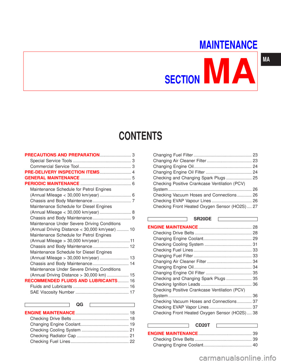
MAINTENANCE
SECTION
MA
CONTENTS
PRECAUTIONS AND PREPARATION.......................... 3
Special Service Tools ................................................ 3
Commercial Service Tool ........................................... 3
PRE-DELIVERY INSPECTION ITEMS.......................... 4
GENERAL MAINTENANCE.......................................... 5
PERIODIC MAINTENANCE.......................................... 6
Maintenance Schedule for Petrol Engines
(Annual Mileage < 30,000 km/year) .......................... 6
Chassis and Body Maintenance ................................ 7
Maintenance Schedule for Diesel Engines
(Annual Mileage < 30,000 km/year) .......................... 8
Chassis and Body Maintenance ................................ 9
Maintenance Under Severe Driving Conditions
(Annual Driving Distance < 30,000 km/year) .......... 10
Maintenance Schedule for Petrol Engines
(Annual Mileage > 30,000 km/year) ......................... 11
Chassis and Body Maintenance .............................. 12
Maintenance Schedule for Diesel Engines
(Annual Mileage > 30,000 km/year) ........................ 13
Chassis and Body Maintenance .............................. 14
Maintenance Under Severe Driving Conditions
(Annual Driving Distance > 30,000 km) .................. 15
RECOMMENDED FLUIDS AND LUBRICANTS......... 16
Fluids and Lubricants .............................................. 16
SAE Viscosity Number ............................................ 17
QG
ENGINE MAINTENANCE............................................ 18
Checking Drive Belts ............................................... 18
Changing Engine Coolant........................................ 19
Checking Cooling System ....................................... 21
Checking Radiator Cap ........................................... 21
Checking Fuel Lines ................................................ 22Changing Fuel Filter ................................................ 23
Changing Air Cleaner Filter ..................................... 23
Changing Engine Oil................................................ 24
Changing Engine Oil Filter ...................................... 24
Checking and Changing Spark Plugs ..................... 25
Checking Positive Crankcase Ventilation (PCV)
System ..................................................................... 26
Checking Vacuum Hoses and Connections ............ 26
Checking EVAP Vapour Lines ................................. 26
Checking Front Heated Oxygen Sensor (HO2S) .... 27
SR20DE
ENGINE MAINTENANCE............................................ 28
Checking Drive Belts ............................................... 28
Changing Engine Coolant........................................ 29
Checking Cooling System ....................................... 31
Checking Fuel Lines ................................................ 33
Changing Fuel Filter ................................................ 33
Changing Air Cleaner Filter ..................................... 34
Changing Engine Oil................................................ 34
Changing Engine Oil Filter ...................................... 35
Checking and Changing Spark Plugs ..................... 35
Checking Ignition Leads .......................................... 36
Checking Positive Crankcase Ventilation (PCV)
System ..................................................................... 36
Checking Vacuum Hoses and Connections ............ 37
Checking EVAP Vapor Lines ................................... 37
Checking Front Heated Oxygen Sensor (HO2S) .... 38
CD20T
ENGINE MAINTENANCE............................................ 39
Checking Drive Belts ............................................... 39
Changing Engine Coolant........................................ 40
MA
Page 2019 of 2267
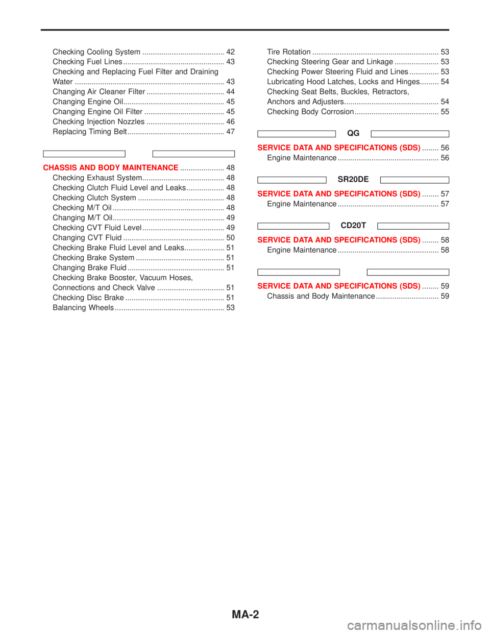
Checking Cooling System ....................................... 42
Checking Fuel Lines ................................................ 43
Checking and Replacing Fuel Filter and Draining
Water ....................................................................... 43
Changing Air Cleaner Filter ..................................... 44
Changing Engine Oil................................................ 45
Changing Engine Oil Filter ...................................... 45
Checking Injection Nozzles ..................................... 46
Replacing Timing Belt .............................................. 47
CHASSIS AND BODY MAINTENANCE..................... 48
Checking Exhaust System....................................... 48
Checking Clutch Fluid Level and Leaks .................. 48
Checking Clutch System ......................................... 48
Checking M/T Oil ..................................................... 48
Changing M/T Oil..................................................... 49
Checking CVT Fluid Level ....................................... 49
Changing CVT Fluid ................................................ 50
Checking Brake Fluid Level and Leaks................... 51
Checking Brake System .......................................... 51
Changing Brake Fluid .............................................. 51
Checking Brake Booster, Vacuum Hoses,
Connections and Check Valve ................................ 51
Checking Disc Brake ............................................... 51
Balancing Wheels .................................................... 53Tire Rotation ............................................................ 53
Checking Steering Gear and Linkage ..................... 53
Checking Power Steering Fluid and Lines .............. 53
Lubricating Hood Latches, Locks and Hinges......... 54
Checking Seat Belts, Buckles, Retractors,
Anchors and Adjusters............................................. 54
Checking Body Corrosion ........................................ 55
QG
SERVICE DATA AND SPECIFICATIONS (SDS)........ 56
Engine Maintenance ................................................ 56
SR20DE
SERVICE DATA AND SPECIFICATIONS (SDS)........ 57
Engine Maintenance ................................................ 57
CD20T
SERVICE DATA AND SPECIFICATIONS (SDS)........ 58
Engine Maintenance ................................................ 58
SERVICE DATA AND SPECIFICATIONS (SDS)........ 59
Chassis and Body Maintenance .............................. 59
MA-2
Page 2021 of 2267
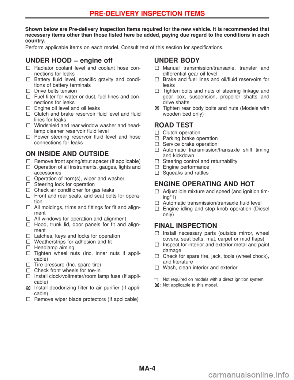
Shown below are Pre-delivery Inspection Items required for the new vehicle. It is recommended that
necessary items other than those listed here be added, paying due regard to the conditions in each
country.
Perform applicable items on each model. Consult text of this section for specifications.
UNDER HOOD � engine off
Radiator coolant level and coolant hose con-
nections for leaks
Battery fluid level, specific gravity and condi-
tions of battery terminals
Drive belts tension
Fuel filter for water or dust, fuel lines and con-
nections for leaks
Engine oil level and oil leaks
Clutch and brake reservoir fluid level and fluid
lines for leaks
Windshield and rear window washer and head-
lamp cleaner reservoir fluid level
Power steering reservoir fluid level and hose
connections for leaks
ON INSIDE AND OUTSIDE
Remove front spring/strut spacer (If applicable)
Operation of all instruments, gauges, lights and
accessories
Operation of horn(s), wiper and washer
Steering lock for operation
Check air conditioner for gas leaks
Front and rear seats, and seat belts for opera-
tion
All moldings, trims and fittings for fit and align-
ment
All windows for operation and alignment
Hood, trunk lid, door panels for fit and align-
ment
Latches, keys and locks for operation
Weatherstrips for adhesion and fit
Headlamp aiming
Tighten wheel nuts (Inc. inner nuts if appli-
cable)
Tire pressure (Inc. spare tire)
Check front wheels for toe-in
Install clock/voltmeter/room lamp fuse (If appli-
cable)
Install deodorizing filter to air purifier (If appli-
cable)
Remove wiper blade protectors (If applicable)
UNDER BODY
Manual transmission/transaxle, transfer and
differential gear oil level
Brake and fuel lines and oil/fluid reservoirs for
leaks
Tighten bolts and nuts of steering linkage and
gear box, suspension, propeller shafts and
drive shafts
Tighten rear body bolts and nuts (Models with
wooden bed only)
ROAD TEST
Clutch operation
Parking brake operation
Service brake operation
Automatic transmission/transaxle shift timing
and kickdown
Steering control and returnability
Engine performance
Squeaks and rattles
ENGINE OPERATING AND HOT
Adjust idle mixture and speed (and ignition tim-
ing*1)
Automatic transmission/transaxle fluid level
Engine idling and stop knob operation (Diesel
only)
FINAL INSPECTION
Install necessary parts (outside mirror, wheel
covers, seat belts, mat, carpet or mud flaps)
Inspect for interior and exterior metal and paint
damage
Check for spare tire, jack, tools (wheel chock),
and literature
Wash, clean interior and exterior
*1: Not required on models with a direct ignition system
: Not applicable to this model.
PRE-DELIVERY INSPECTION ITEMS
MA-4
Page 2023 of 2267
![NISSAN PRIMERA 1999 Electronic Repair Manual Maintenance Schedule for Petrol Engines
(Annual Mileage < 30,000 km/year)
QG16DE/QG18DE/SR20DE engines
Abbreviations: R = Replace I = Inspect: Correct or replace if necessary [ ] = At the specified mi NISSAN PRIMERA 1999 Electronic Repair Manual Maintenance Schedule for Petrol Engines
(Annual Mileage < 30,000 km/year)
QG16DE/QG18DE/SR20DE engines
Abbreviations: R = Replace I = Inspect: Correct or replace if necessary [ ] = At the specified mi](/manual-img/5/57377/w960_57377-2022.png)
Maintenance Schedule for Petrol Engines
(Annual Mileage < 30,000 km/year)
QG16DE/QG18DE/SR20DE engines
Abbreviations: R = Replace I = Inspect: Correct or replace if necessary [ ] = At the specified mileage only
MAINTENANCE OPERATION MAINTENANCE INTERVAL
Perform on a kilometer basis, but on
an annual basis when driving less
than 15,000 km (9,000 miles) per yearkm×1,000 15 30 45 60 75 90 105 120
(miles×1,000) (9) (18) (27) (36) (45) (54) (63) (72)
Months 12 24 36 48 60 72 84 96QG16DE/
QG18DESR20DE
Engine compartment and under vehicleReference pages
Engine oil (Use recommended oil)*RRRRRRRRMA-24 MA-34
Engine oil filter (Use NISSAN genuine
part or equivalent)*RRRRRRRRMA-24 MA-35
Drive beltsIIIIIIIIMA-18 MA-28
Cooling systemIIIIIIIIMA-21 MA-31
Engine anti-freeze coolant (Use genuine
NISSAN Anti-Freeze Coolant (L2N) or
equivalent)See NOTE (1) MA-19 MA-29
Air cleaner filter* R R MA-23 MA-34
Intake and exhaust valve clearance
(Non HLA models)See NOTE (2) EM-92—
Fuel and vapour linesIIIIMA-22/MA-26MA-33/
MA-37
Spark plugs (Conventional type)RRRRMA-25 MA-35
Ignition leads I I—MA-36
Fuel filter*R MA-23 MA-33
Heated oxygen sensor* See NOTE (3)MA-27,
EC-QG-134/
EC-QG-173MA-38,
EC-SR-146/
EC-SR-182
PCVsystem IIIIMA-26MA-36
NOTE: (1) First replace at 90,000 km (54,000 miles)/72 months, then every 60,000 km (36,000 miles)/48 months.
(2) Periodic maintenance is not required for QG engine models. However, if valve noise increases, check valve clear-
ance.
(3) Perform only according to“Maintenance under severe driving conditions”.
* Maintenance items with“*”should be performed more frequently according to“Maintenance under severe driv-
ing conditions”.
PERIODIC MAINTENANCE
MA-6