Page 668 of 2267
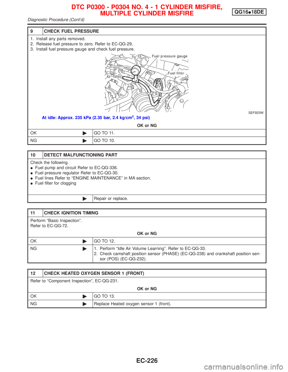
9 CHECK FUEL PRESSURE
1. Install any parts removed.
2. Release fuel pressure to zero. Refer to EC-QG-29.
3. Install fuel pressure gauge and check fuel pressure.
SEF925W
At idle: Approx. 235 kPa (2.35 bar, 2.4 kg/cm2, 34 psi)
OK or NG
OK©GO TO 11.
NG©GO TO 10.
10 DETECT MALFUNCTIONING PART
Check the following.
IFuel pump and circuit Refer to EC-QG-336.
IFuel pressure regulator Refer to EC-QG-30.
IFuel lines Refer to ªENGINE MAINTENANCEº in MA section.
IFuel filter for clogging
©Repair or replace.
11 CHECK IGNITION TIMING
Perform ªBasic Inspectionº.
Refer to EC-QG-72.
OK or NG
OK©GO TO 12.
NG©1. Perform ªIdle Air Volume Learningº. Refer to EC-QG-33.
2. Check camshaft position sensor (PHASE) (EC-QG-238) and crankshaft position sen-
sor (POS) (EC-QG-232).
12 CHECK HEATED OXYGEN SENSOR 1 (FRONT)
Refer to ªComponent Inspectionº, EC-QG-231.
OK or NG
OK©GO TO 13.
NG©Replace Heated oxygen sensor 1 (front).
DTC P0300 - P0304 NO.4-1CYLINDER MISFIRE,
MULTIPLE CYLINDER MISFIREQG16I18DE
Diagnostic Procedure (Cont'd)
EC-226
Page 821 of 2267
Vacuum Hose DrawingNCEC0012Refer to ªSystem Diagramº on EC-SR-20 for vacuum control system.
NOTE:
Do not use soapy water or any type of solvent while installing vacuum hoses or purge hoses.
SEF191X Intake manifold collector
Throttle body
Rear view (Left side)Rear view (Right side)
Intake manifold collector
Fuel pressure
regulator
To brake
booster
Air hose to
power steering
air valve
EVAP purge line to engine
Fuel filter
To EVAP
canister
(RHD models)
EVAP purge volume
control solenoid valve
To EVAP
canister
(LHD models)
Front view
EVAP purge
line to
engine
EVAP canister
(LHD models)
Power steering air valve
To intake manifold
collector
Air tube for power
steering air valve
To EVAP
canister
(RHD models)
ENGINE AND EMISSION CONTROL OVERALL SYSTEMSR20DE
Vacuum Hose Drawing
EC-21
Page 829 of 2267
EVAPORATIVE EMISSION LINE DRAWINGNCEC0020NOTE:
Do not use soapy water or any type of solvent while installing
vacuum hoses or purge hoses.
SEF193X Intake manifold collector
Throttle body
Rear view (Left side)Rear view (Right side)
Intake manifold collector
Fuel pressure
regulator
To brake
booster
Air hose to
power steering
air valve
EVAP purge line to engine
Fuel filter
To EVAP
canister
(RHD models)
EVAP purge volume
control solenoid valve
To EVAP
canister
(LHD models)
Front view
EVAP purge
line to
engine
EVAP canister
(LHD models)
Power steering air valve
To intake manifold
collector
Air tube for power
steering air valve
To EVAP
canister
(RHD models)
ENGINE AND EMISSION BASIC CONTROL
SYSTEM DESCRIPTIONSR20DE
Evaporative Emission System (Cont'd)
EC-29
Page 831 of 2267
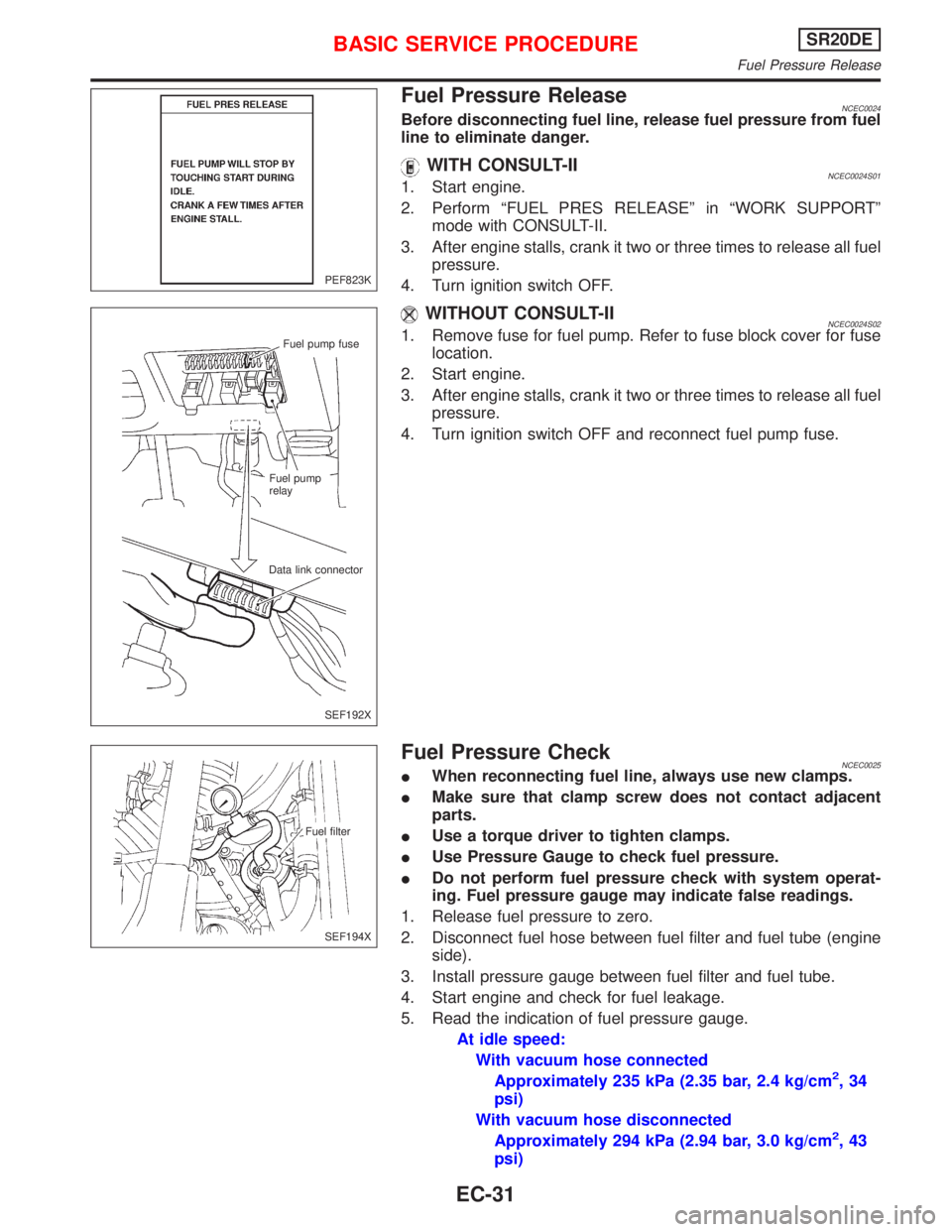
Fuel Pressure ReleaseNCEC0024Before disconnecting fuel line, release fuel pressure from fuel
line to eliminate danger.
WITH CONSULT-IINCEC0024S011. Start engine.
2. Perform ªFUEL PRES RELEASEº in ªWORK SUPPORTº
mode with CONSULT-II.
3. After engine stalls, crank it two or three times to release all fuel
pressure.
4. Turn ignition switch OFF.
WITHOUT CONSULT-IINCEC0024S021. Remove fuse for fuel pump. Refer to fuse block cover for fuse
location.
2. Start engine.
3. After engine stalls, crank it two or three times to release all fuel
pressure.
4. Turn ignition switch OFF and reconnect fuel pump fuse.
Fuel Pressure CheckNCEC0025IWhen reconnecting fuel line, always use new clamps.
IMake sure that clamp screw does not contact adjacent
parts.
IUse a torque driver to tighten clamps.
IUse Pressure Gauge to check fuel pressure.
IDo not perform fuel pressure check with system operat-
ing. Fuel pressure gauge may indicate false readings.
1. Release fuel pressure to zero.
2. Disconnect fuel hose between fuel filter and fuel tube (engine
side).
3. Install pressure gauge between fuel filter and fuel tube.
4. Start engine and check for fuel leakage.
5. Read the indication of fuel pressure gauge.
At idle speed:
With vacuum hose connected
Approximately 235 kPa (2.35 bar, 2.4 kg/cm
2,34
psi)
With vacuum hose disconnected
Approximately 294 kPa (2.94 bar, 3.0 kg/cm
2,43
psi)
PEF823K
Fuel pump fuse
Fuel pump
relay
Data link connector
SEF192X
Fuel filter
SEF194X
BASIC SERVICE PROCEDURESR20DE
Fuel Pressure Release
EC-31
Page 897 of 2267
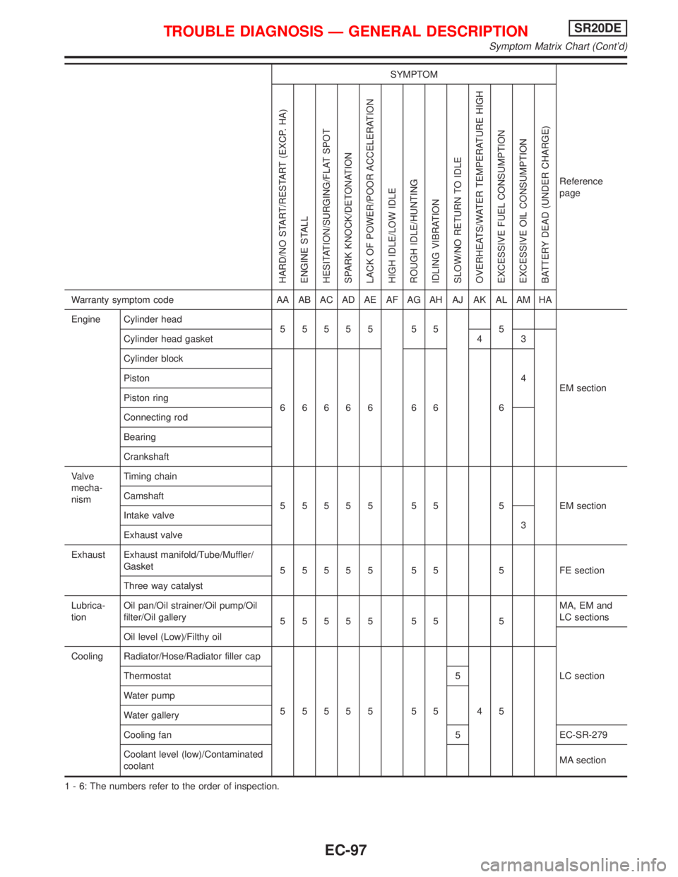
SYMPTOM
Reference
page
HARD/NO START/RESTART (EXCP. HA)
ENGINE STALL
HESITATION/SURGING/FLAT SPOT
SPARK KNOCK/DETONATION
LACK OF POWER/POOR ACCELERATION
HIGH IDLE/LOW IDLE
ROUGH IDLE/HUNTING
IDLING VIBRATION
SLOW/NO RETURN TO IDLE
OVERHEATS/WATER TEMPERATURE HIGH
EXCESSIVE FUEL CONSUMPTION
EXCESSIVE OIL CONSUMPTION
BATTERY DEAD (UNDER CHARGE)
Warranty symptom code AA AB AC AD AE AF AG AH AJ AK AL AM HA
Engine Cylinder head
55555 55 5
EM section Cylinder head gasket 4 3
Cylinder block
66666 66 64 Piston
Piston ring
Connecting rod
Bearing
Crankshaft
Valve
mecha-
nismTiming chain
55555 55 5 EMsection Camshaft
Intake valve
3
Exhaust valve
Exhaust Exhaust manifold/Tube/Muffler/
Gasket
55555 55 5 FEsection
Three way catalyst
Lubrica-
tionOil pan/Oil strainer/Oil pump/Oil
filter/Oil gallery
55555 55 5MA, EM and
LC sections
Oil level (Low)/Filthy oil
LC section Cooling Radiator/Hose/Radiator filler cap
55555 55 45 Thermostat 5
Water pump
Water gallery
Cooling fan 5 EC-SR-279
Coolant level (low)/Contaminated
coolantMA section
1 - 6: The numbers refer to the order of inspection.
TROUBLE DIAGNOSIS Ð GENERAL DESCRIPTIONSR20DE
Symptom Matrix Chart (Cont'd)
EC-97
Page 1015 of 2267
4 CHECK FUEL PRESSURE
1. Release fuel pressure to zero.
Refer to EC-SR-31.
2. Install fuel pressure gauge and check fuel pressure.
At idling:
When fuel pressure regulator valve vacuum hose is connected.
235 kPa (2.35 bar, 2.4 kg/cm
2, 34 psi)
When fuel pressure regulator valve vacuum hose is disconnected.
294 kPa (2.94 bar, 3.0 kg/cm
2, 43 psi)
OK or NG
OK©GO TO 6.
NG©GO TO 5.
5 DETECT MALFUNCTIONING PART
Check the following.
IFuel pump and circuit Refer to EC-SR-316.
IFuel pressure regulator Refer to EC-SR-32.
IFuel lines Refer to ªENGINE MAINTENANCEº in MA section.
IFuel filter for clogging
©Repair or replace.
6 CHECK MASS AIR FLOW SENSOR
With CONSULT-II
Check ªMASS AIR FLOWº in ªDATA MONITORº mode with CONSULT-II.
at idling: 2.5 - 5.0 g×m/sec
at 2,500 rpm: 7.1 - 12.5 g×m/sec
With GST
Check mass air flow sensor signal in MODE 1 with GST.
at idling: 2.5 - 5.0 g×m/sec
at 2,500 rpm: 7.1 - 12.5 g×m/sec
OK or NG
OK©GO TO 7.
NG©Check connectors for rusted terminals or loose connections in the mass air flow sensor
circuit or engine grounds. Refer to EC-SR-120.
DTC P0171 FUEL INJECTION SYSTEM FUNCTION
(LEAN SIDE)SR20DE
Diagnostic Procedure (Cont'd)
EC-215
Page 1027 of 2267
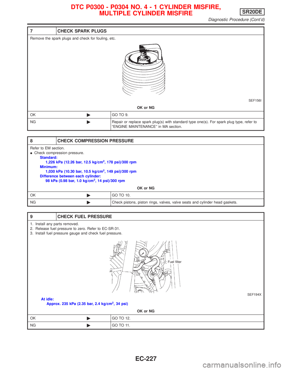
7 CHECK SPARK PLUGS
Remove the spark plugs and check for fouling, etc.
SEF156I
OK or NG
OK©GO TO 9.
NG©Repair or replace spark plug(s) with standard type one(s). For spark plug type, refer to
ªENGINE MAINTENANCEº in MA section.
8 CHECK COMPRESSION PRESSURE
Refer to EM section.
ICheck compression pressure.
Standard:
1,226 kPa (12.26 bar, 12.5 kg/cm
2, 178 psi)/300 rpm
Minimum:
1,030 kPa (10.30 bar, 10.5 kg/cm
2, 149 psi)/300 rpm
Difference between each cylinder:
98 kPa (0.98 bar, 1.0 kg/cm
2, 14 psi)/300 rpm
OK or NG
OK©GO TO 10.
NG©Check pistons, piston rings, valves, valve seats and cylinder head gaskets.
9 CHECK FUEL PRESSURE
1. Install any parts removed.
2. Release fuel pressure to zero. Refer to EC-SR-31.
3. Install fuel pressure gauge and check fuel pressure.
SEF194XAt idle:
Approx. 235 kPa (2.35 bar, 2.4 kg/cm2, 34 psi)
OK or NG
OK©GO TO 12.
NG©GO TO 11.
Fuel filter
DTC P0300 - P0304 NO.4-1CYLINDER MISFIRE,
MULTIPLE CYLINDER MISFIRESR20DE
Diagnostic Procedure (Cont'd)
EC-227
Page 1028 of 2267
10 DETECT MALFUNCTIONING PART
Check the following.
IFuel pump and circuit Refer to EC-SR-320.
IFuel pressure regulator Refer to EC-SR-32.
IFuel lines Refer to ªENGINE MAINTENANCEº in MA section.
IFuel filter for clogging
©Repair or replace.
11 CHECK IGNITION TIMING
Perform ªBasic Inspectionº, EC-SR-84.
OK or NG
OK©GO TO 13.
NG©Adjust ignition timing.
12 CHECK HEATED OXYGEN SENSOR 1 (FRONT)
Refer to ªComponent Inspectionº, EC-SR-154.
OK or NG
OK©GO TO 14.
NG©Replace heated oxygen sensor 1 (front).
13 CHECK MASS AIR FLOW SENSOR
With CONSULT-II
Check ªMASS AIR FLOWº in ªDATA MONITORº mode with CONSULT-II.
at idling: 2.5 - 5.0 g×m/sec
at 2,500 rpm: 7.1 - 12.5 g×m/sec
With GST
Check mass air flow sensor signal in MODE 1 with GST.
at idling: 2.5 - 5.0 g×m/sec
at 2,500 rpm: 7.1 - 12.5 g×m/sec
OK or NG
OK©GO TO 16.
NG©GO TO 15.
14 CHECK CONNECTORS
Check connectors for rusted terminals or loose connections in the mass air flow sensor circuit or engine grounds.
Refer to EC-SR-120.
OK or NG
NG©Repair or replace it.
15 CHECK SYMPTOM MATRIX CHART
Check items on the rough idle symptom in ªSymptom Matrix Chartº, EC-SR-94.
OK or NG
OK©GO TO 17.
NG©Repair or replace.
DTC P0300 - P0304 NO.4-1CYLINDER MISFIRE,
MULTIPLE CYLINDER MISFIRESR20DE
Diagnostic Procedure (Cont'd)
EC-228