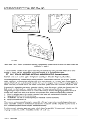
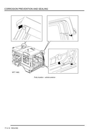
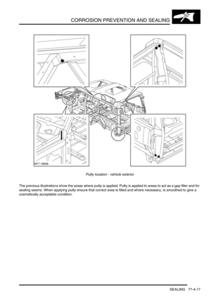
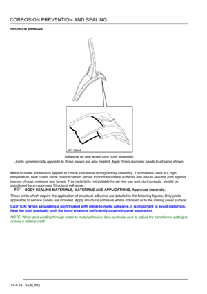
Page 25 of 1529

CONTENTS
22 CONTENTS
PANEL REPAIRS...................................................................................... 77-2-1
REPLACEMENT PANELS
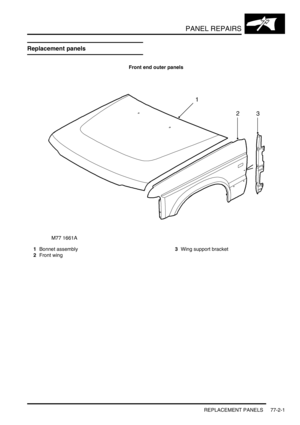
Replacement panels ....................................................................................................................... 77-2-1
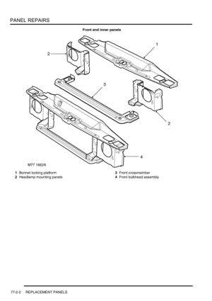
Front end inner panels .................................................................................................................... 77-2-2
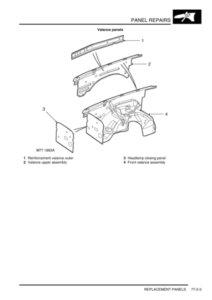
Valance panels .............................................................................................................................. 77-2-3
Body side panels ............................................................................................................................ 77-2-4
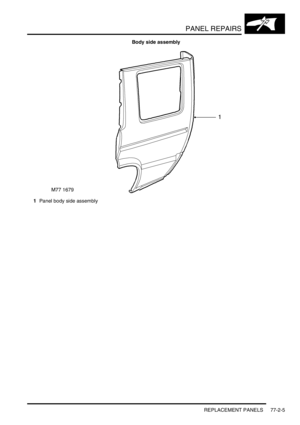
Body side assembly ........................................................................................................................ 77-2-5
'D'-post assembly............................................................................................................................ 77-2-6
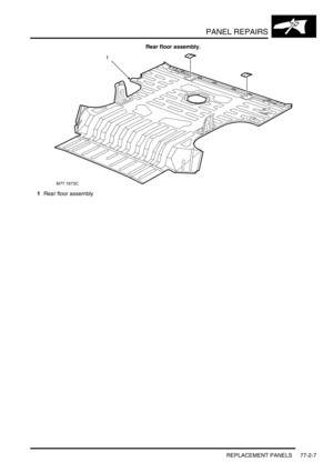
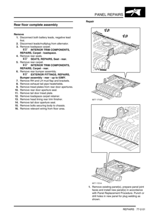
Rear floor assembly. ....................................................................................................................... 77-2-7
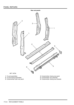
Rear end panels ............................................................................................................................ 77-2-8
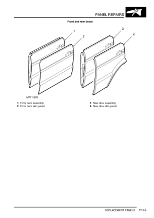
Front and rear doors ....................................................................................................................... 77-2-9
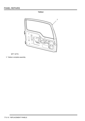
Taildoor ........................................................................................................................................... 77-2-10
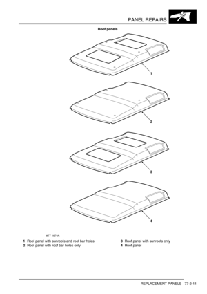
Roof panels..................................................................................................................................... 77-2-11
Replacement panels ....................................................................................................................... 77-2-12
PROCEDURES
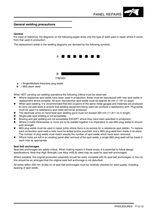
General welding precautions .......................................................................................................... 77-2-13
Electronic control units.................................................................................................................... 77-2-14
PROCEDURES
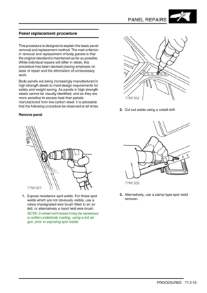
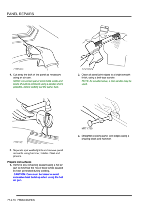
Panel replacement procedure......................................................................................................... 77-2-15
REPAIRS
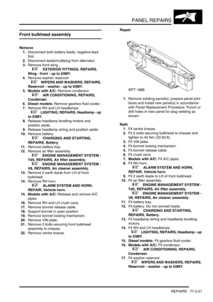
Front bulkhead assembly................................................................................................................ 77-2-21
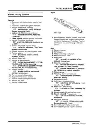
Bonnet locking platform .................................................................................................................. 77-2-23
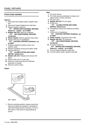
Front cross member........................................................................................................................ 77-2-24
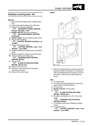
Headlamp mounting panel - RH ..................................................................................................... 77-2-25
Headlamp mounting panel - LH ...................................................................................................... 77-2-26
Valance upper assembly - LH......................................................................................................... 77-2-28
Valance upper assembly - RH ........................................................................................................ 77-2-29
Valance upper assembly (front section) - LH.................................................................................. 77-2-30
Valance upper assembly (front section) - RH ................................................................................. 77-2-32
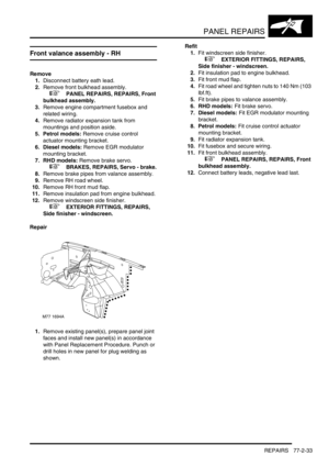
Front valance assembly - RH ......................................................................................................... 77-2-33
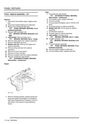
Front valance assembly - LH ......................................................................................................... 77-2-34
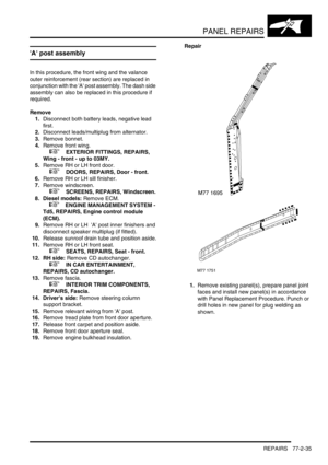
'A' post assembly ............................................................................................................................ 77-2-35
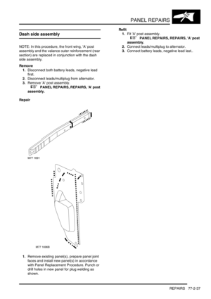
Dash side assembly........................................................................................................................ 77-2-37
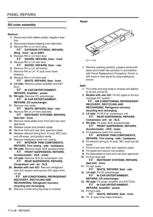
Sill outer assembly.......................................................................................................................... 77-2-38
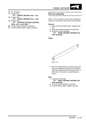
Sill inner assembly .......................................................................................................................... 77-2-39
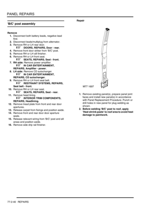
'B/C' post assembly ........................................................................................................................ 77-2-40
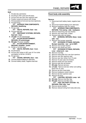
Panel body side assembly .............................................................................................................. 77-2-41
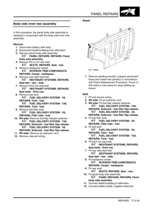
Body side inner rear assembly ....................................................................................................... 77-2-43
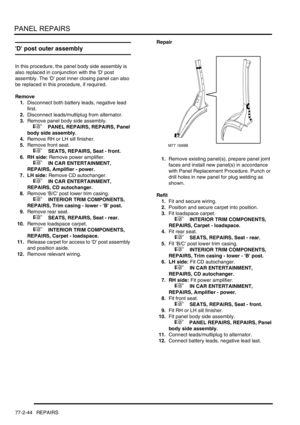
'D' post outer assembly................................................................................................................... 77-2-44
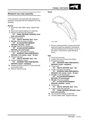
Wheelarch rear outer assembly ...................................................................................................... 77-2-45
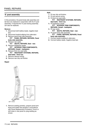
'E' post assembly ............................................................................................................................ 77-2-46
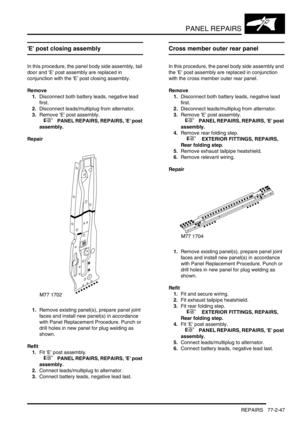
'E' post closing assembly ................................................................................................................ 77-2-47
Cross member outer rear panel ...................................................................................................... 77-2-47
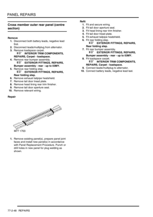
Cross member outer rear panel (centre section) ............................................................................ 77-2-48
Cross member outer rear panel (RH/LH section) ........................................................................... 77-2-49
Cross member closing rear panel ................................................................................................... 77-2-49
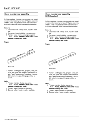
Cross member rear assembly......................................................................................................... 77-2-50
Cross member rear assembly (RH/LH section) .............................................................................. 77-2-50
Rear floor complete assembly ........................................................................................................ 77-2-51
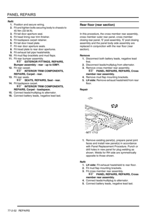
Rear floor (rear section) .................................................................................................................. 77-2-52
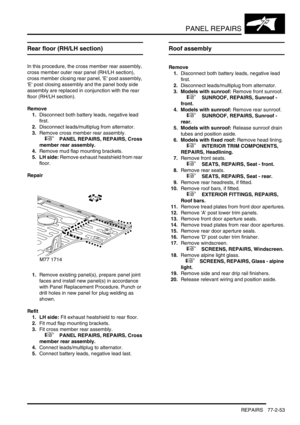
Rear floor (RH/LH section) ............................................................................................................. 77-2-53
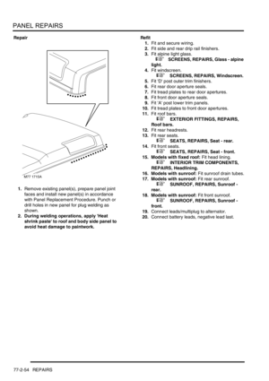
Roof assembly ............................................................................................................................... 77-2-53
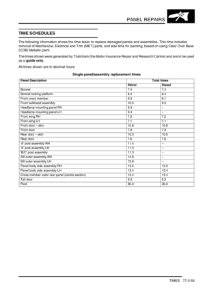
TIMES
TIME SCHEDULES ........................................................................................................................ 77-2-55
Page 26 of 1529

CONTENTS
CONTENTS 23
BODY SEALING MATERIALS ................................................................. 77-3-1
MATERIALS AND APPLICATIONS
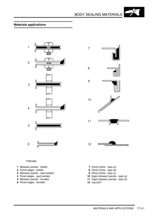
Materials applications ..................................................................................................................... 77-3-1
Approved materials ......................................................................................................................... 77-3-2
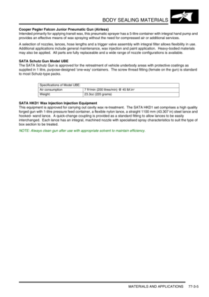
Application equipment..................................................................................................................... 77-3-4
CORROSION PREVENTION AND SEALING .......................................... 77-4-1
CORROSION PREVENTION
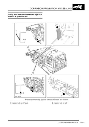
Cavity wax treatment areas and injection holes - 'A' post and sill ................................................... 77-4-1
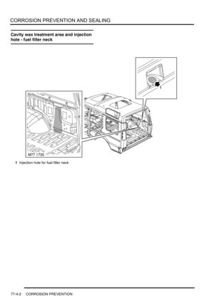
Cavity wax treatment area and injection hole - fuel filler neck ........................................................ 77-4-2
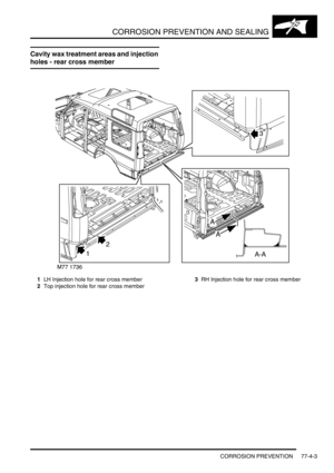
Cavity wax treatment areas and injection holes - rear cross member ............................................ 77-4-3
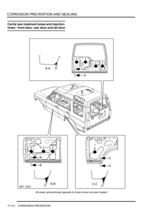
Cavity wax treatment areas and injection holes - front door, rear door and tail door ...................... 77-4-4
Corrosion prevention....................................................................................................................... 77-4-6
SEALING
Body Sealing ................................................................................................................................... 77-4-9
Water leaks ..................................................................................................................................... 77-4-22
PAINTING ................................................................................................ 77-5-1
PROCEDURES
Panel preparation............................................................................................................................ 77-5-1
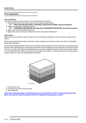
Paint preparation............................................................................................................................. 77-5-2
HEATING AND VENTILATION................................................................. 80-1
DESCRIPTION AND OPERATION
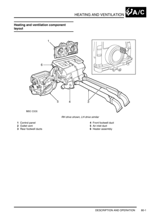
Heating and ventilation component layout ...................................................................................... 80-1
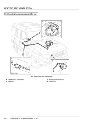
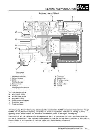
Fuel burning heater component layout ........................................................................................... 80-2
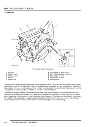
Description ...................................................................................................................................... 80-3
Operation ........................................................................................................................................ 80-13
REPAIRS
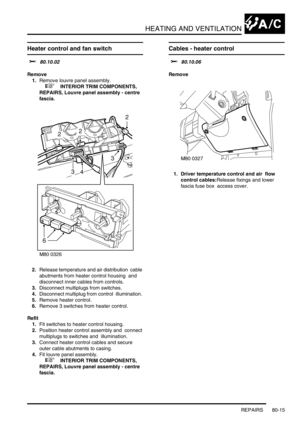
Heater control and fan switch ....................................................................................................... 80-15
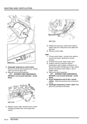
Cables - heater control .................................................................................................................. 80-15
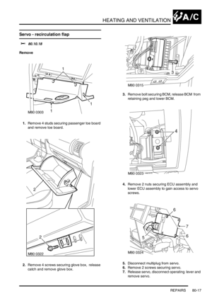
Servo - recirculation flap ............................................................................................................... 80-17
Switch - recirculation control ......................................................................................................... 80-18
Servo - air distribution control ........................................................................................................ 80-19
Servo - air temperature control ....................................................................................................... 80-20
Plenum Air Intake ........................................................................................................................... 80-21
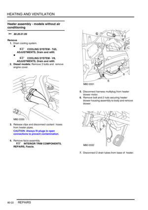
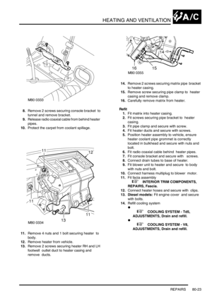
Heater assembly - models without air conditioning ......................................................................... 80-22
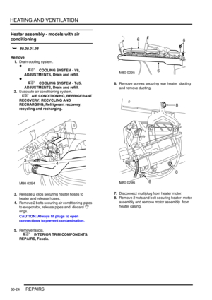
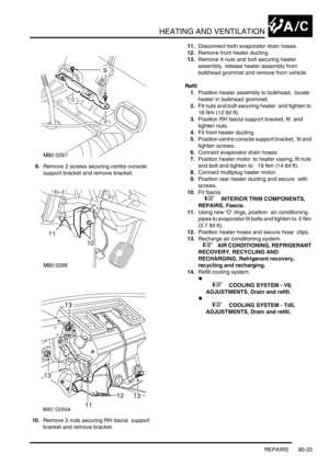
Heater assembly - models with air conditioning .............................................................................. 80-24
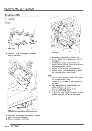
Blower assembly ............................................................................................................................ 80-26
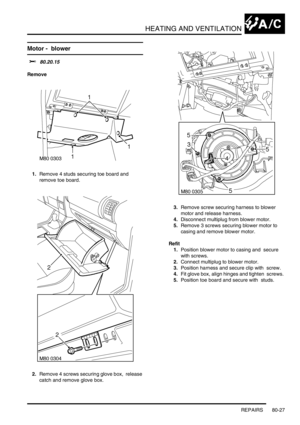
Motor - blower ............................................................................................................................. 80-27
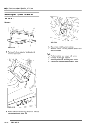
Resistor pack - power resistor A/C ............................................................................................... 80-28
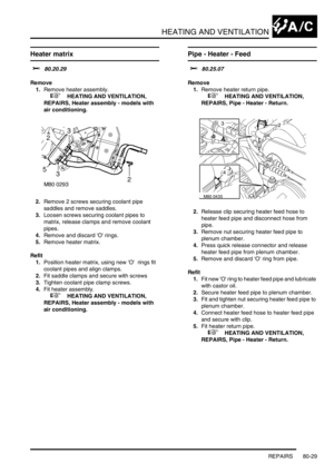
Heater matrix ................................................................................................................................ 80-29
Pipe - Heater - Feed ...................................................................................................................... 80-29
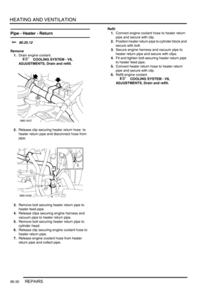
Pipe - Heater - Return .................................................................................................................... 80-30
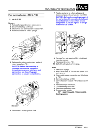
Fuel burning heater - (FBH) - Td5................................................................................................... 80-31
Page 27 of 1529

CONTENTS
24 CONTENTS
AIR CONDITIONING ................................................................................. 82-1
DESCRIPTION AND OPERATION
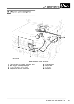
A/C refrigerant system component layout....................................................................................... 82-1
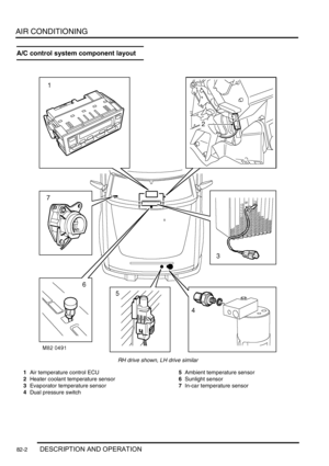
A/C control system component layout ............................................................................................ 82-2
Description ...................................................................................................................................... 82-3
Operation ........................................................................................................................................ 82-16
DESCRIPTION AND OPERATION
Rear A/C refrigerant system component layout .............................................................................. 82-21
Rear A/C distribution and control component layout ...................................................................... 82-22
Description ...................................................................................................................................... 82-23
Operation ........................................................................................................................................ 82-26
REFRIGERANT RECOVERY, RECYCLING AND RECHARGING
Refrigerant recovery, recycling and recharging .............................................................................. 82-27
REPAIRS
Compressor - diesel........................................................................................................................ 82-29
Compressor - V8............................................................................................................................. 82-30
Fan - condenser ............................................................................................................................ 82-31
Condenser .................................................................................................................................... 82-31
Receiver drier and dual pressure switch......................................................................................... 82-33
ECU - air temperature control ......................................................................................................... 82-35
Sensor - ambient air temperature ................................................................................................ 82-35
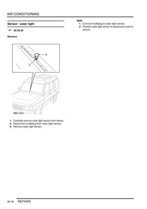
Sensor - solar light ........................................................................................................................ 82-36
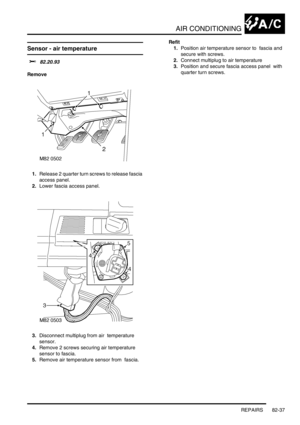
Sensor - air temperature ............................................................................................................. 82-37
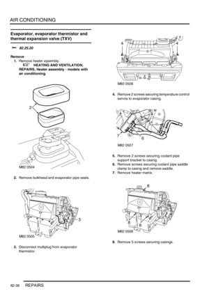
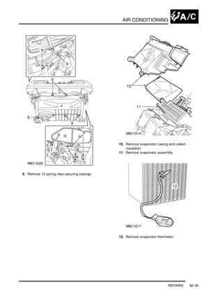
Evaporator, evaporator thermistor and thermal expansion valve (TXV) ........................................ 82-38
Expansion valve - (TXV) - rear ....................................................................................................... 82-41
Evaporator - rear............................................................................................................................. 82-42
Evaporator and motor assembly - rear ........................................................................................... 82-43
Blower motor assembly - rear ......................................................................................................... 82-44
Resistor - blower motor ................................................................................................................. 82-45
Duct - centre - rear.......................................................................................................................... 82-45
Page 28 of 1529

CONTENTS
CONTENTS 25
WIPERS AND WASHERS ........................................................................ 84-1
DESCRIPTION AND OPERATION
Wipers and washers component layout .......................................................................................... 84-1
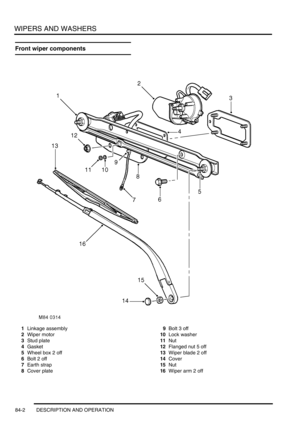
Front wiper components ................................................................................................................. 84-2
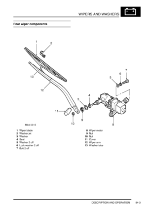
Rear wiper components .................................................................................................................. 84-3
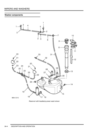
Washer components ....................................................................................................................... 84-4
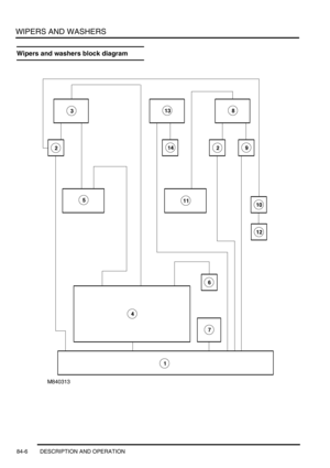
Wipers and washers block diagram ................................................................................................ 84-6
Description ...................................................................................................................................... 84-8
Operation ........................................................................................................................................ 84-17
REPAIRS
Reservoir - washer - up to 03MY .................................................................................................... 84-21
Reservoir - washer - from 03MY ..................................................................................................... 84-22
Jet - washer - windscreen ............................................................................................................... 84-23
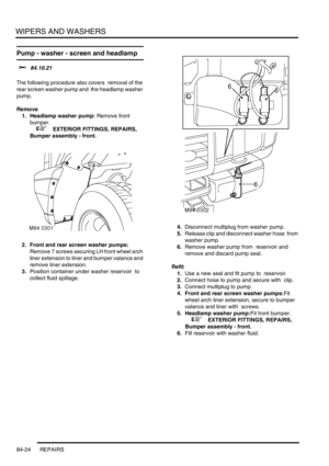
Pump - washer - screen and headlamp ....................................................................................... 84-24
Motor and linkage - wiper - windscreen .......................................................................................... 84-25
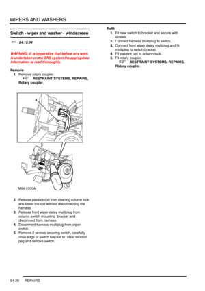
Switch - wiper and washer - windscreen ......................................................................................... 84-26
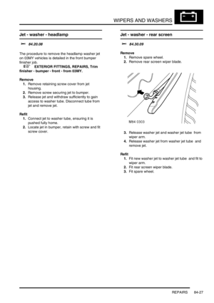
Jet - washer - headlamp ................................................................................................................ 84-27
Jet - washer - rear screen ............................................................................................................ 84-27
Switch - rear wash .......................................................................................................................... 84-28
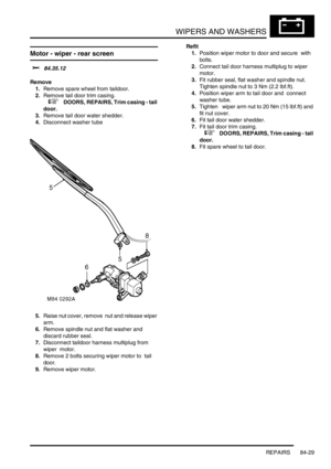
Motor - wiper - rear screen ............................................................................................................. 84-29
Switch - wiper - rear - up to 03MY .................................................................................................. 84-30
Switch - wiper - rear - from 03MY ................................................................................................... 84-30
CHARGING AND STARTING ................................................................... 86-1-1
REPAIRS
Alternator - diesel .......................................................................................................................... 86-1-1
Alternator - V8 ................................................................................................................................. 86-1-3
Belt - auxiliary drive ......................................................................................................................... 86-1-4
Battery ............................................................................................................................................ 86-1-4
Battery carrier ................................................................................................................................ 86-1-5
Starter motor - diesel ...................................................................................................................... 86-1-6
Starter motor - V8 ........................................................................................................................... 86-1-7
Page 29 of 1529

CONTENTS
26 CONTENTS
LIGHTING.................................................................................................. 86-2-1
ADJUSTMENTS
Headlamps beam alignment - up to 03MY ..................................................................................... 86-2-1
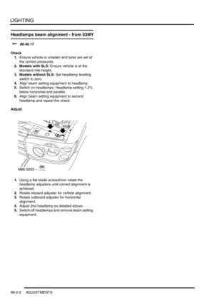
Headlamps beam alignment - from 03MY ...................................................................................... 86-2-2
REPAIRS
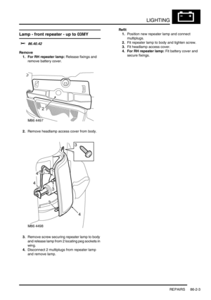
Lamp - front repeater - up to 03MY ................................................................................................ 86-2-3
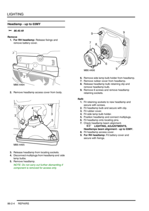
Headlamp - up to 03MY .................................................................................................................. 86-2-4
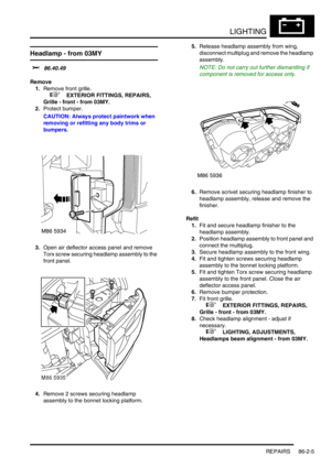
Headlamp - from 03MY .................................................................................................................. 86-2-5
Lamp - tail ..................................................................................................................................... 86-2-6
Lamp - front fog up to 03MY ........................................................................................................... 86-2-6
Lamp - front fog from 03MY ............................................................................................................ 86-2-7
Housing - number plate lamp ......................................................................................................... 86-2-8
Motor - headlamp levelling ............................................................................................................ 86-2-9
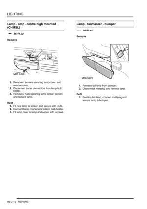
Lamp - stop - centre high mounted (CHMSL) .............................................................................. 86-2-10
Lamp - tail/flasher - bumper ............................................................................................................ 86-2-10
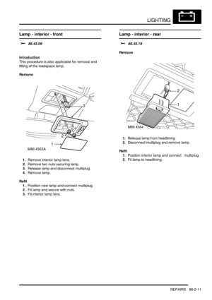
Lamp - interior - front .................................................................................................................... 86-2-11
Lamp - interior - rear ..................................................................................................................... 86-2-11
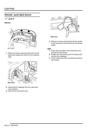
Rheostat - panel lights dimmer ...................................................................................................... 86-2-12
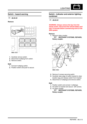
Switch - hazard warning ................................................................................................................ 86-2-13
Switch - indicator and exterior lighting - combined ......................................................................... 86-2-13
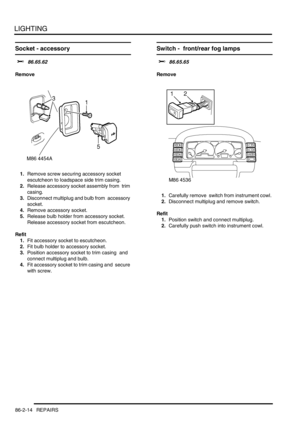
Socket - accessory ........................................................................................................................ 86-2-14
Switch - front/rear fog lamps ......................................................................................................... 86-2-14
BODY CONTROL UNIT ............................................................................ 86-3-1
DESCRIPTION AND OPERATION
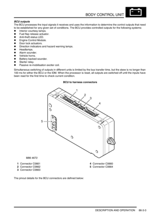
Description ...................................................................................................................................... 86-3-1
Operation ........................................................................................................................................ 86-3-19
REPAIRS
Body control unit (BCU) .................................................................................................................. 86-3-35
ALARM SYSTEM AND HORN.................................................................. 86-4-1
DESCRIPTION AND OPERATION
Alarm system component layout..................................................................................................... 86-4-2
Alarm system block diagram........................................................................................................... 86-4-4
Description ...................................................................................................................................... 86-4-5
Operation ........................................................................................................................................ 86-4-17
REPAIR
Switch - central door locking ......................................................................................................... 86-4-25
Switches - horn ............................................................................................................................. 86-4-25
Vehicle horn .................................................................................................................................. 86-4-26
Sounder - alarm ............................................................................................................................ 86-4-26
Sounder - battery backed-up (BBUS) ............................................................................................. 86-4-27
Switch - bonnet ............................................................................................................................. 86-4-27
Receiver - alarm system - models with sunroof ............................................................................. 86-4-28
Receiver - alarm system - models without sunroof ......................................................................... 86-4-28
Coil - passive immobilisation ........................................................................................................ 86-4-29
Page 30 of 1529

CONTENTS
CONTENTS 27
WINDOWS ................................................................................................ 86-5-1
DESCRIPTION AND OPERATION
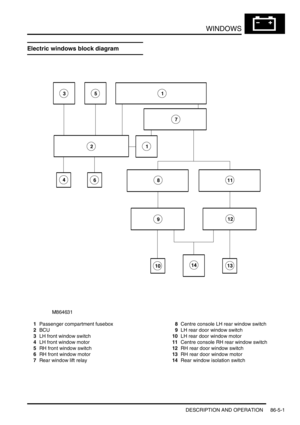
Electric windows block diagram ...................................................................................................... 86-5-1
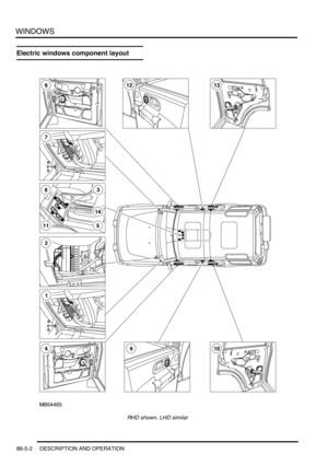
Electric windows component layout ................................................................................................ 86-5-2
Description ...................................................................................................................................... 86-5-4
Operation ....................................................................................................................................... 86-5-11
REPAIRS
Switch - rear door .......................................................................................................................... 86-5-13
Switch - console ............................................................................................................................ 86-5-13
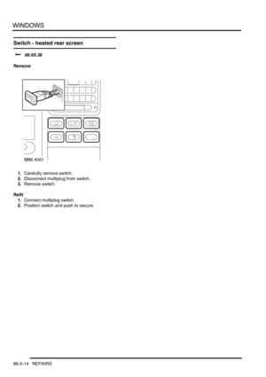
Switch - heated rear screen ............................................................................................................ 86-5-14
IN CAR ENTERTAINMENT ...................................................................... 86-6-1
DESCRIPTION AND OPERATION
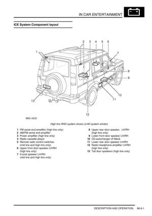
ICE System Component layout ....................................................................................................... 86-6-1
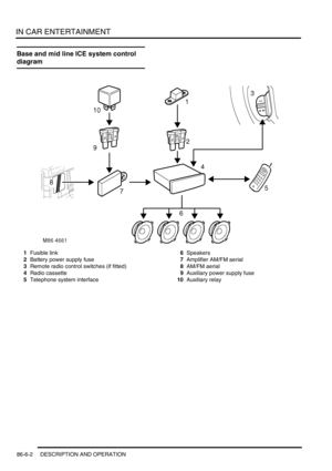
Base and mid line ICE system control diagram .............................................................................. 86-6-2
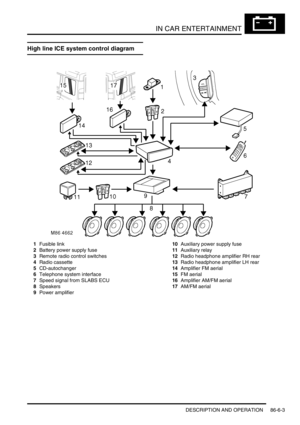
High line ICE system control diagram ............................................................................................. 86-6-3
Description ...................................................................................................................................... 86-6-4
DESCRIPTION AND OPERATION
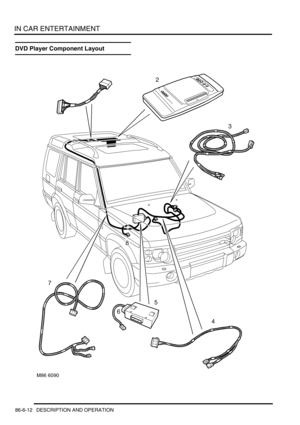
DVD Player Component Layout ...................................................................................................... 86-6-12
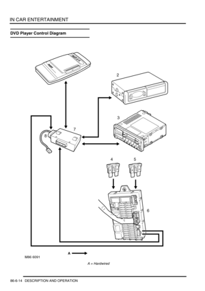
DVD Player Control Diagram .......................................................................................................... 86-6-14
Description ...................................................................................................................................... 86-6-16
Operation ........................................................................................................................................ 86-6-27
REPAIRS
Radio ............................................................................................................................................. 86-6-31
Speaker - low/full range - front door .............................................................................................. 86-6-32
Speaker - low range - rear door ..................................................................................................... 86-6-32
Switches - remote control - ICE .................................................................................................... 86-6-33
Amplifier - aerial .............................................................................................................................. 86-6-33
Speaker - mid range - front door ................................................................................................... 86-6-34
Speaker - high range - rear door ................................................................................................... 86-6-34
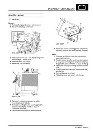
Amplifier - power ........................................................................................................................... 86-6-35
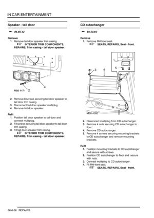
Speaker - tail door ......................................................................................................................... 86-6-36
CD autochanger ............................................................................................................................ 86-6-36
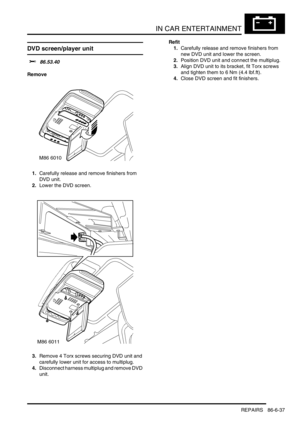
DVD screen/player unit .................................................................................................................. 86-6-37
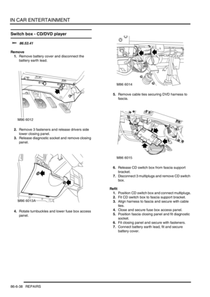
Switch box - CD/DVD player ........................................................................................................... 86-6-38
HARNESSES ............................................................................................ 86-7-1
REPAIRS
Harness - injectors - diesel ............................................................................................................ 86-7-1
Harness - body .............................................................................................................................. 86-7-1
Harness - engine - V8 ..................................................................................................................... 86-7-8
Harness - engine - diesel ................................................................................................................ 86-7-12
Harness - main .............................................................................................................................. 86-7-15
Harness - main - DVD unit ............................................................................................................. 86-7-28
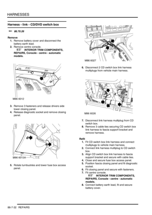
Harness - link - CD/DVD switch box ............................................................................................... 86-7-32
Page 31 of 1529

CONTENTS
28 CONTENTS
DRIVING AIDS .......................................................................................... 86-8-1
DESCRIPTION AND OPERATION
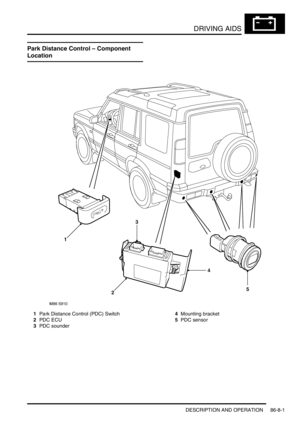
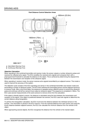
Park Distance Control – Component Location................................................................................ 86-8-1
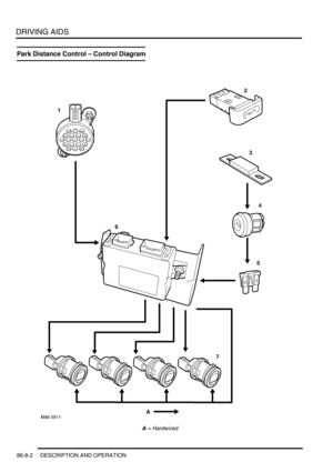
Park Distance Control – Control Diagram....................................................................................... 86-8-2
Description ...................................................................................................................................... 86-8-4
Operation ........................................................................................................................................ 86-8-11
REPAIRS
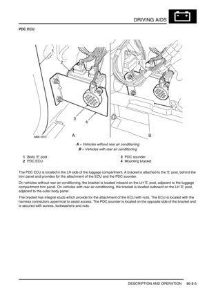
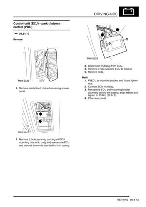
Control unit (ECU) - park distance control (PDC) ........................................................................... 86-8-13
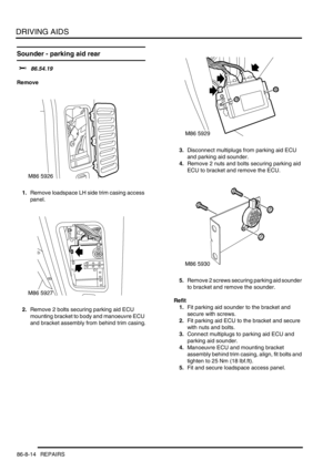
Sounder - parking aid rear ............................................................................................................. 86-8-14
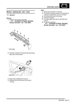
Sensor - parking aid - rear - inner ................................................................................................... 86-8-15
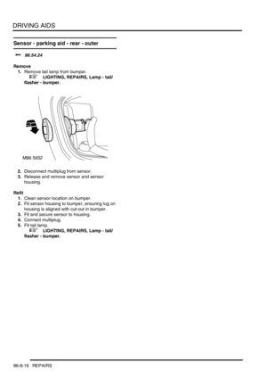
Sensor - parking aid - rear - outer .................................................................................................. 86-8-16
NAVIGATION SYSTEM ............................................................................ 87-1
DESCRIPTION AND OPERATION
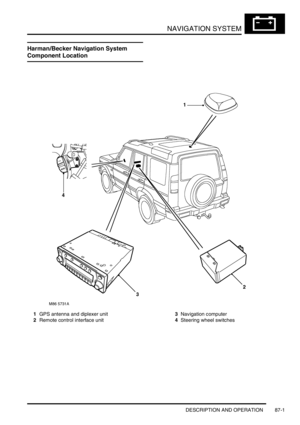
Harman/Becker Navigation System Component Location.............................................................. 87-1
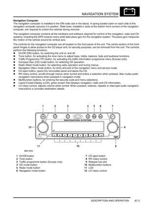
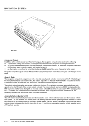
Description ...................................................................................................................................... 87-2
DESCRIPTION AND OPERATION
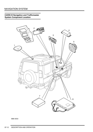
CARiN III Navigation and Trafficmaster System Component Location........................................... 87-12
Description ...................................................................................................................................... 87-14
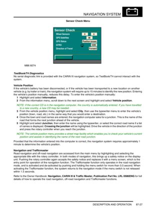
Operation ........................................................................................................................................ 87-20
REPAIRS
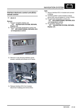
Interface electronic control unit (ECU) - remote control ................................................................. 87-29
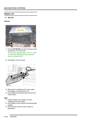
Display unit .................................................................................................................................... 87-30
INSTRUMENTS ......................................................................................... 88-1
DESCRIPTION AND OPERATION
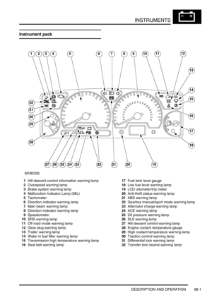
Instrument pack .............................................................................................................................. 88-1
Instrument component location - Engine compartment / underneath vehicle ................................. 88-2
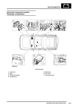
Instrument component location - Passenger compartment ............................................................ 88-3
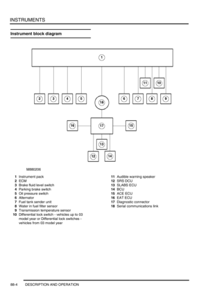
Instrument block diagram ............................................................................................................... 88-4
Description ...................................................................................................................................... 88-5
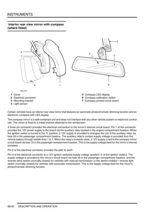
Interior rear view mirror with compass (where fitted) ..................................................................... 88-42
REPAIRS
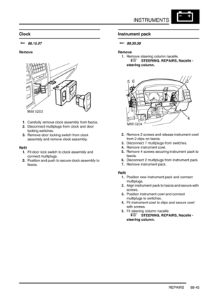
Clock ............................................................................................................................................... 88-45
Instrument pack ............................................................................................................................ 88-45
Page 32 of 1529

INTRODUCTION
01-1
INTRODUCTION
How To Use This Manual
Introduction
This Manual is designed to assist skilled technicians
in the efficient repair and maintenance of Discovery
vehicles.
Individuals who undertake their own repairs should
have some skill and training, and limit repairs to
components which could not affect the safety of the
vehicle or its passengers. Any repairs required to
safety critical items such as steering, brakes,
suspension or supplementary restraint system
should be carried out by a Land Rover Dealer.
Repairs to such items should NEVER be attempted
by untrained individuals.
General
To assist in the use of this Manual, it is divided into
sections and sub-sections. The section title is given
at the top of each page and the relevant sub-section
is given at the bottom.
There is a single contents section at the front of the
Manual, which is divided by section and sub-section.
Each section is numbered from page 1.
The individual items comprising repair operations are
to be followed in the sequence in which they appear.
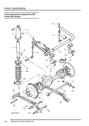
Items numbers in the illustration are referred to in the
text.
Adjustment and Repair operations include reference
to Service tool numbers and the associated
illustration depicts the tool in use. Adjustment and
repair operations also include reference to wear
limits, relevant data, torque figures, and specialist
information and useful assembly details. Each
adjustment or repair operation is given its Service
Repair Operation number.
WARNINGS, CAUTIONS and NOTES have the
following meanings:
WARNING: Procedures which must be followed
precisely to avoid the possibility of injury.
CAUTION: Calls attention to procedures which
must be followed to avoid damage to
components.
NOTE: Gives helpful information.References
References to the LH or RH side given in this Manual
are made when viewing the vehicle from the rear.
With the engine and gearbox assembly removed, the
crankshaft pulley end of the engine is referred to as
the front.
Operations covered in this Manual do not include
reference to testing the vehicle after repair. It is
essential that work is inspected and tested after
completion and if necessary a road test of the vehicle
is carried out particularly where safety related items
are concerned.
Dimensions
The dimensions quoted are to design engineering
specification with Service limits where applicable.