1999 LAND ROVER DISCOVERY tow bar
[x] Cancel search: tow barPage 22 of 1529

CONTENTS
CONTENTS 19
EXTERIOR FITTINGS ............................................................................... 76-2-1
REPAIRS
Wing - front - up to 03MY ................................................................................................................ 76-2-1
Wing - front - from 03MY ................................................................................................................. 76-2-2
Rear folding step ............................................................................................................................ 76-2-4
Liner - wheel arch - front ................................................................................................................. 76-2-5
Liner - wheel arch - rear ................................................................................................................. 76-2-6
Panel - underbelly .......................................................................................................................... 76-2-7
Mirror - exterior - electric ................................................................................................................ 76-2-7
Roof bars ....................................................................................................................................... 76-2-8
Bonnet ........................................................................................................................................... 76-2-9
Cable - bonnet release - up to 03MY .............................................................................................. 76-2-9
Cable - bonnet release - from 03MY ............................................................................................... 76-2-11
Bumper assembly - front ............................................................................................................... 76-2-12
Bumper assembly - rear - from 03MY ............................................................................................. 76-2-13
Trim finisher - bumper - front - from 03MY ...................................................................................... 76-2-14
Bumper assembly - rear - up to 03MY ............................................................................................ 76-2-15
Side finisher - windscreen .............................................................................................................. 76-2-16
Grille - front - up to 03MY................................................................................................................ 76-2-16
Grille - front - from 03MY ................................................................................................................ 76-2-17
INTERIOR TRIM COMPONENTS ............................................................. 76-3-1
REPAIRS
Trim casing - tail door speaker ...................................................................................................... 76-3-1
Trim casing - side - loadspace ....................................................................................................... 76-3-2
Trim casing - upper - 'B' post ......................................................................................................... 76-3-3
Trim casing - lower - 'B' post ......................................................................................................... 76-3-3
Trim casing - 'D' post ...................................................................................................................... 76-3-4
Console - centre - automatic models .............................................................................................. 76-3-5
Console - centre - manual models .................................................................................................. 76-3-7
Fascia ............................................................................................................................................. 76-3-10
Panel - auxiliary switch ................................................................................................................... 76-3-14
Panel - fascia access - driver's side .............................................................................................. 76-3-15
Drink tray assembly - centre fascia ................................................................................................. 76-3-15
Louvre panel assembly - centre fascia ........................................................................................... 76-3-16
Carpet - front ................................................................................................................................... 76-3-18
Carpet - rear .................................................................................................................................. 76-3-19
Carpet - loadspace ......................................................................................................................... 76-3-20
Headlining ...................................................................................................................................... 76-3-20
Stowage pocket - front .................................................................................................................. 76-3-24
Page 65 of 1529

GENERAL DATA
04-2
Lubrication
Type Wet sump, pressure fed
Pump type Eccentric rotor, crankshaft driven integral with stiffener plate.
Filter type:
⇒ Primary Centrifuge filter
⇒ Secondary Disposable canister with full flow by-pass
Pressure at idle (Cold) 3.0 bar (43.5 lbf.in
2)
Pressure at 3500 rev/min (Hot) 1.5-3.0 bar (21.75-43.5 lbf.in
2)
Relief valve opening pressure 4.0 bar (58 lbf.in
2)
Low oil pressure switch opening pressure 0.2-0.6 bar (3.0-8.8 lbf.in
2)
Crankshaft
Main journal diameter 61.9875-62.0125 mm (2.4404-2.4414 in)
Crankpin journal diameter 53.99-54.01 mm (2.125-2.131 in)
End float 0.020 - 0.250 mm (0.0008 - 0.0098 in)
Main bearings
Quantity 6 (5 main, 1 thrust)
Pistons
Type Graphite compound skirt with combustion chamber in crown
Clearance in cylinder bore.
Measured at bottom of skirt, 90° to gudgeon pin0.172-0.206 mm (0.007-0.008 in)
Diameter
(Measured at right angles to gudgeon pin and 40.0 mm
(1.5 in) from bottom of skirt)84.270-85.254 mm (3.321-3.361 in)
Gudgeon pins Fully floating, offset towards piston thrust side
Piston rings
Type: 2 compression, 1 oil control
⇒ Upper compression ring Barrel edge, chrome plated
⇒ Lower compression ring Taper faced
⇒ Oil control ring Bevelled ring with spring
New ring to groove clearance:
⇒ Upper compression Not measured
⇒ Lower compression 0.050-0.082 mm (0.002-0.003 in)
⇒ Oil control 0.050-0.082 mm (0.002-0.003 in)
Piston ring fitted gap in cylinder bore:
⇒ Upper compression 0.30-0.45 mm (0.0118-0.0177 in)
⇒ Lower compression 0.40-0.60 mm (0.0157-0.0236 in)
⇒ Oil control 0.25-0.40 mm (0.0098-0.0157 in)
Camshaft
Bearings 6
Drive Duplex chain
End float 0.06-0.16 mm (0.002-0.006 in)
Tappets
Type Hydraulic lash adjusters with followers
Page 83 of 1529

GENERAL DATA
04-20
Wheels and tyres
CAUTION: When towing, the additional load imposed may cause the tyre maximum load rating to be
exceeded. This is permissible provided the load rating is not exceeded by more than 15% and that road
speeds are limited to 62 mph (100 km/h) and tyres pressures are increased by at least 3 lbf/in
2 (0.2 bar).
NOTE: The tyre size is displayed on the outer wall of each tyre.
Normal operating conditions: carrying up to 4 passengers and luggage.
Wheel size:
⇒ Steel 7J x 16
⇒ Alloy 7J x 16
8J x 16
8J x 18
Tyre size
⇒ With 7J x 16 wheels 235/70 R16 Wrangler HP 105H
235/70 R16 Michelin XPC * 105H
⇒ With 8J x 16 wheels 255/65 R16 Wrangler HP 109H
255/65 R16 Michelin XPC * 109H
⇒ With 8J x 18 wheels 255/55 R18 Wrangler HP 109H
Tyre Pressures
All tyres - normal operating conditions Front Up to 03MY - 1.9 Bar (28 lbf.in
2)
From 03MY - 2.1 Bar (30 lbf.in2)
Rear 2.6 Bar (38 lbf.in
2)
All tyres - vehicle at GVW Front Up to 03MY - 1.9 Bar (28 lbf.in
2)
From 03MY - 2.1 Bar (30 lbf.in2)
Rear 3.2 Bar (46 lbf.in
2)
Page 86 of 1529

GENERAL DATA
04-23
Dimensions
* Measurement taken with vehicle at unladen weight.
Overall length - including towing hitch 4715 mm (185.6 in)
Overall length - including spare wheel 4705 mm (185.24 in)
Overall width (excluding mirrors) 1885 mm (74.2 in)
Overall height - Open sunroof * 2015 mm (79.3 in)
Overall height (without roof bars) * 1940 mm (76.40 in)
Minimum ground clearance * 253.5 mm (10.0 in)
Wheelbase 2540 mm (100.00 in)
Turning circle (kerb to kerb) 11.9 metres (39.1 feet)
Track - front 1540 mm (60.63 in)
Track - rear 1560 mm (61.42 in)
Page 1014 of 1529

SEATS
REPAIRS 76-5-17
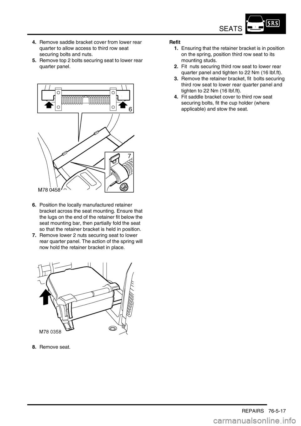
4.Remove saddle bracket cover from lower rear
quarter to allow access to third row seat
securing bolts and nuts.
5.Remove top 2 bolts securing seat to lower rear
quarter panel.
6.Position the locally manufactured retainer
bracket across the seat mounting. Ensure that
the lugs on the end of the retainer fit below the
seat mounting bar, then partially fold the seat
so that the retainer bracket is held in position.
7.Remove lower 2 nuts securing seat to lower
rear quarter panel. The action of the spring will
now hold the retainer bracket in place.
8.Remove seat.Refit
1.Ensuring that the retainer bracket is in position
on the spring, position third row seat to its
mounting studs.
2.Fit nuts securing third row seat to lower rear
quarter panel and tighten to 22 Nm (16 lbf.ft).
3.Remove the retainer bracket, fit bolts securing
third row seat to lower rear quarter panel and
tighten to 22 Nm (16 lbf.ft).
4.Fit saddle bracket cover to third row seat
securing bolts, fit the cup holder (where
applicable) and stow the seat.
Page 1026 of 1529

SEATS
REPAIRS 76-5-29
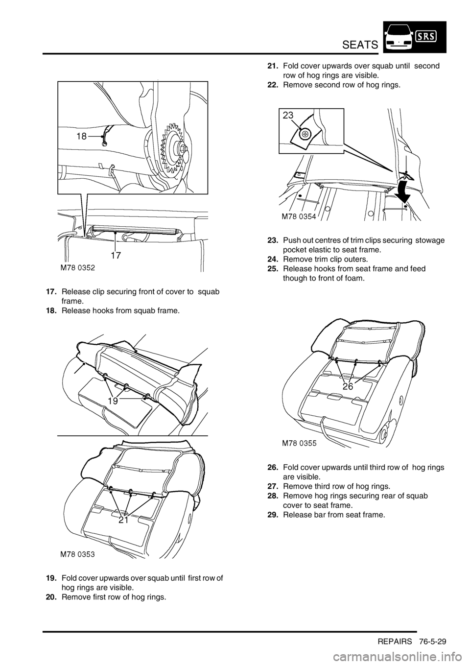
17.Release clip securing front of cover to squab
frame.
18.Release hooks from squab frame.
19.Fold cover upwards over squab until first row of
hog rings are visible.
20.Remove first row of hog rings. 21.Fold cover upwards over squab until second
row of hog rings are visible.
22.Remove second row of hog rings.
23.Push out centres of trim clips securing stowage
pocket elastic to seat frame.
24.Remove trim clip outers.
25.Release hooks from seat frame and feed
though to front of foam.
26.Fold cover upwards until third row of hog rings
are visible.
27.Remove third row of hog rings.
28.Remove hog rings securing rear of squab
cover to seat frame.
29.Release bar from seat frame.
Page 1027 of 1529

SEATS
76-5-30 REPAIRS
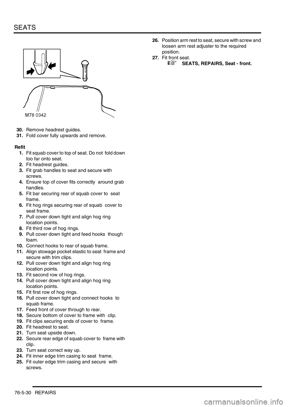
30.Remove headrest guides.
31.Fold cover fully upwards and remove.
Refit
1.Fit squab cover to top of seat. Do not fold down
too far onto seat.
2.Fit headrest guides.
3.Fit grab handles to seat and secure with
screws.
4.Ensure top of cover fits correctly around grab
handles.
5.Fit bar securing rear of squab cover to seat
frame.
6.Fit hog rings securing rear of squab cover to
seat frame.
7.Pull cover down tight and align hog ring
location points.
8.Fit third row of hog rings.
9.Pull cover down tight and feed hooks though
foam.
10.Connect hooks to rear of squab frame.
11.Align stowage pocket elastic to seat frame and
secure with trim clips.
12.Pull cover down tight and align hog ring
location points.
13.Fit second row of hog rings.
14.Pull cover down tight and align hog ring
location points.
15.Fit first row of hog rings.
16.Pull cover down tight and connect hooks to
squab frame.
17.Feed front of cover through to rear.
18.Secure bottom of cover to frame with clip.
19.Fit clips securing ends of cover to frame.
20.Fit headrest to seat.
21.Turn seat upside down.
22.Secure rear edge of squab cover to frame with
clip.
23.Turn seat correct way up.
24.Fit inner edge trim casing to seat frame.
25.Fit outer edge trim casing and secure with
screws. 26.Position arm rest to seat, secure with screw and
loosen arm rest adjuster to the required
position.
27.Fit front seat.
+ SEATS, REPAIRS, Seat - front.