1999 LAND ROVER DISCOVERY ECO mode
[x] Cancel search: ECO modePage 9 of 1529

CONTENTS
6CONTENTS
EMISSION CONTROL - V8 ....................................................................... 17-2-1
DESCRIPTION AND OPERATION
Crankcase emission control system ............................................................................................... 17-2-1
Exhaust emission control ................................................................................................................ 17-2-2
Evaporative emission system component layout ............................................................................ 17-2-3
Evaporative emission system (with positive pressure leak detection) component layout (NAS only) 17-2-4
Evaporative emission system control diagram ............................................................................... 17-2-5
Secondary air injection system component layout.......................................................................... 17-2-6
Secondary air injection system control diagram ............................................................................. 17-2-8
Emission Control Systems .............................................................................................................. 17-2-9
Crankcase Emission Control System ............................................................................................. 17-2-10
Exhaust Emission Control System.................................................................................................. 17-2-11
Evaporative Emission Control System............................................................................................ 17-2-15
Secondary Air Injection System ...................................................................................................... 17-2-26
Crankcase Emission Control Operation.......................................................................................... 17-2-34
Exhaust Emission Control Operation .............................................................................................. 17-2-35
Evaporative Emission Control Operation ........................................................................................ 17-2-39
Secondary Air Injection System Operation ..................................................................................... 17-2-43
SAI System Fault Finding and Check Malfunctions ........................................................................ 17-2-44
REPAIRS
Canister - EVAP ............................................................................................................................ 17-2-51
Canister - EVAP - Models with Fuel Leak Detection Pump - up to 03MY ...................................... 17-2-52
Canister - EVAP - Models with Fuel Leak Detection Pump - from 03MY ....................................... 17-2-53
Valve - purge control ..................................................................................................................... 17-2-54
Solenoid - evap canister vent solenoid (CVS) valve ..................................................................... 17-2-55
Sensor - heated oxygen (HO2S) - pre-catalytic converter .............................................................. 17-2-56
Sensor - heated oxygen (HO2S) - post-catalytic converter ............................................................ 17-2-57
Control Valve - Secondary Air Injection (SAI) ............................................................................... 17-2-58
Reservoir - Vacuum - Secondary Air Injection (SAI) - up to 03MY ................................................. 17-2-58
Reservoir - vacuum - Secondary Air Injection (SAI) - from 03MY .................................................. 17-2-59
Pump - Air - Secondary Air Injection (SAI) ..................................................................................... 17-2-59
Air Manifold - LH - Secondary Air Injection (SAI) ........................................................................... 17-2-60
Air Manifold - RH - Secondary Air Injection (SAI) .......................................................................... 17-2-61
Solenoid - Vacuum - Secondary Air Injection (SAI) ...................................................................... 17-2-62
Pipe - Secondary Air Injection (SAI) .............................................................................................. 17-2-62
Pump - Fuel Leak Detection - up to 03MY...................................................................................... 17-2-64
Pump - fuel leak detection - from 03MY ......................................................................................... 17-2-64
Filter - fuel leak detection pump - up to 03MY ................................................................................ 17-2-65
Filter - fuel leak detection pump - from 03MY ................................................................................. 17-2-65
Page 35 of 1529

INTRODUCTION
01-4
λLambda
lc Low compression
LCD Liquid Crystal Display
LED Light Emitting Diode
LH Left-Hand
LHD Left-Hand Drive
LVS Liquid Vapour Separator
mMetre
µMicro
MAF Mass Air Flow
MAP Manifold Absolute Pressure
MFU Multi-Function Unit
MFL Multi-Function Logic
max. Maximum
MEMS Modular Engine Management
System
MIL Malfunction Indicator Lamp
min. Minimum
MPa MegaPascal
- Minus (tolerance)
' Minute (angle)
mm Millimetre
mph Miles per hour
MPi Multi-Point injection
MY Model Year
NAS North American Specification
(-) Negative (electrical)
Nm Newton metre
No. Number
NO
2Nitrogen Dioxide
NO
xOxides of Nitrogen
NTC Negative Temperature
Coefficient
OBD On Board Diagnostics
o.dia. Outside diameter
ORM Off-road Mode
ΩOhm
PAS Power Assisted Steering
PCV Positive Crankcase Ventilation
PDC Parking Distance Control
% Percentage
+ Plus (tolerance) or Positive
(electrical)
±Plus or minus (tolerance)
PTC Positive Temperature Coefficient
PTFE Polytetrafluorethylene
PWM Pulse Width Modulation
rRadius
:Ratio
ref Reference
RES Rover Engineering Standards
rev/min Revolutions per minute
RF Radio Frequency
RH Right-Hand
RHD Right-Hand Drive
ROM Read Only Memory
RON Research Octane Number
ROV Roll Over ValveROW Rest Of World
SAE Society of Automotive Engineers
" Second (angle)
SLABS Self Levelling and Anti-Lock
Brake System
SLS Self Levelling Suspension
SOHC Single Overhead Camshaft
sp.gr Specific gravity
SRS Supplementary Restraint System
std. Standard
synchro Synchronizer or synchromesh
TDC Top Dead Centre
TMAP Temperature, Manifold Absolute
Pressure
TP Throttle Position
TPS Throttle Position Sensor
TV Torsional Vibration
TXV Thermostatic Expansion Valve
UK United Kingdom
US United States
V Volt
Var. Variable
VIN Vehicle Identification Number
VIS Variable Intake System
VRS Variable Reluctance Sensor
VSS Vehicle Speed Signal
WWatt
Page 36 of 1529

GENERAL INFORMATION
03-1
GENERAL INFORMATION
General Precautions
Dangerous substances
Modern vehicles contain many materials and liquids
which if not handled with care can be hazardous to
both personal health and the environment.
WARNING: Many liquids and other substances
used in motor vehicles are poisonous and should
under no circumstances be consumed and
should, as far as possible, be kept from contact
with the skin. These liquids and substances
include acid, anti-freeze, asbestos, brake fluid,
fuel, windscreen washer additives, lubricants,
refrigerants and various adhesives.
Always read carefully the instructions printed on
labels or stamped on components and obey them
implicitly. Such instructions are included for
reasons of your health and personal safety.
Never disregard them.
Synthetic rubber
Many 'O' rings, seals, hoses, flexible pipes and other
similar items which appear to be natural rubber, are
in fact, made of synthetic materials called
Fluoroelastomers. Under normal operating
conditions this material is safe and does not present
a health hazard. However, if the material is damaged
by fire or excessive heating, it can break down and
produce highly corrosive Hydrofluoric acid.
Contact with Hydrofluoric acid can cause serious
burns on contact with skin. If skin contact does occur:
lRemove any contaminated clothing
immediately.
lIrrigate effected area of skin with a copious
amount of cold water or limewater for 15 to 60
minutes.
lObtain medical assistance immediately.
Should any material be in a burnt or overheated
condition, handle with extreme caution and wear
protective clothing (seamless industrial gloves,
protective apron etc.).
Decontaminate and dispose of gloves immediately
after use.Lubricating oils
Avoid excessive skin contact with used lubricating
oils and always adhere to the health protection
precautions.
WARNING: Avoid excessive skin contact with
used engine oil. Used engine oil contains
potentially harmful contaminants which may
cause skin cancer or other serious skin
disorders.
WARNING: Avoid excessive skin contact with
mineral oil. Mineral oils remove the natural fats
from the skin, leading to dryness, irritation and
dermatitis.
Health protection precautions
The following precautions should be observed at all
times.
lWear protective clothing, including impervious
gloves where practicable.
lAvoid prolonged and repeated contact with oils,
particularly used engine oils.
lDo not put oily rags in pockets.
lAvoid contaminating clothes (particularly those
next to the skin) with oil.
lOveralls must be cleaned regularly. Discard
heavily soiled clothing and oil impregnated
footwear.
lFirst aid treatment should be obtained
immediately for open cuts and wounds.
lApply barrier creams before each work period to
help prevent lubricating oil from contaminating
the skin.
lWash with soap and water to ensure all oil is
removed (proprietary skin cleansers and nail
brushes will help).
lUse moisturisers after cleaning; preparations
containing lanolin help replace the skin's natural
oils which have been removed.
lDo not use petrol/gasoline, kerosene, diesel
fuel, oil, thinners or solvents for cleaning skin.
lWhere practicable, degrease components prior
to handling.
lIf skin disorders develop, obtain medical advice
without delay.
lWear eye protection (e.g. goggles or face
shield) if there is a risk of eye contamination.
Eye wash facilities should be provided in close
vicinity of the work area.
Page 169 of 1529

ENGINE - V8
12-2-14 REPAIRS
Gasket - cylinder head - LH
$% 12.29.02
Remove
1.Remove inlet manifold gasket.
+ MANIFOLDS AND EXHAUST
SYSTEMS - V8, REPAIRS, Gasket - inlet
manifold - lower.
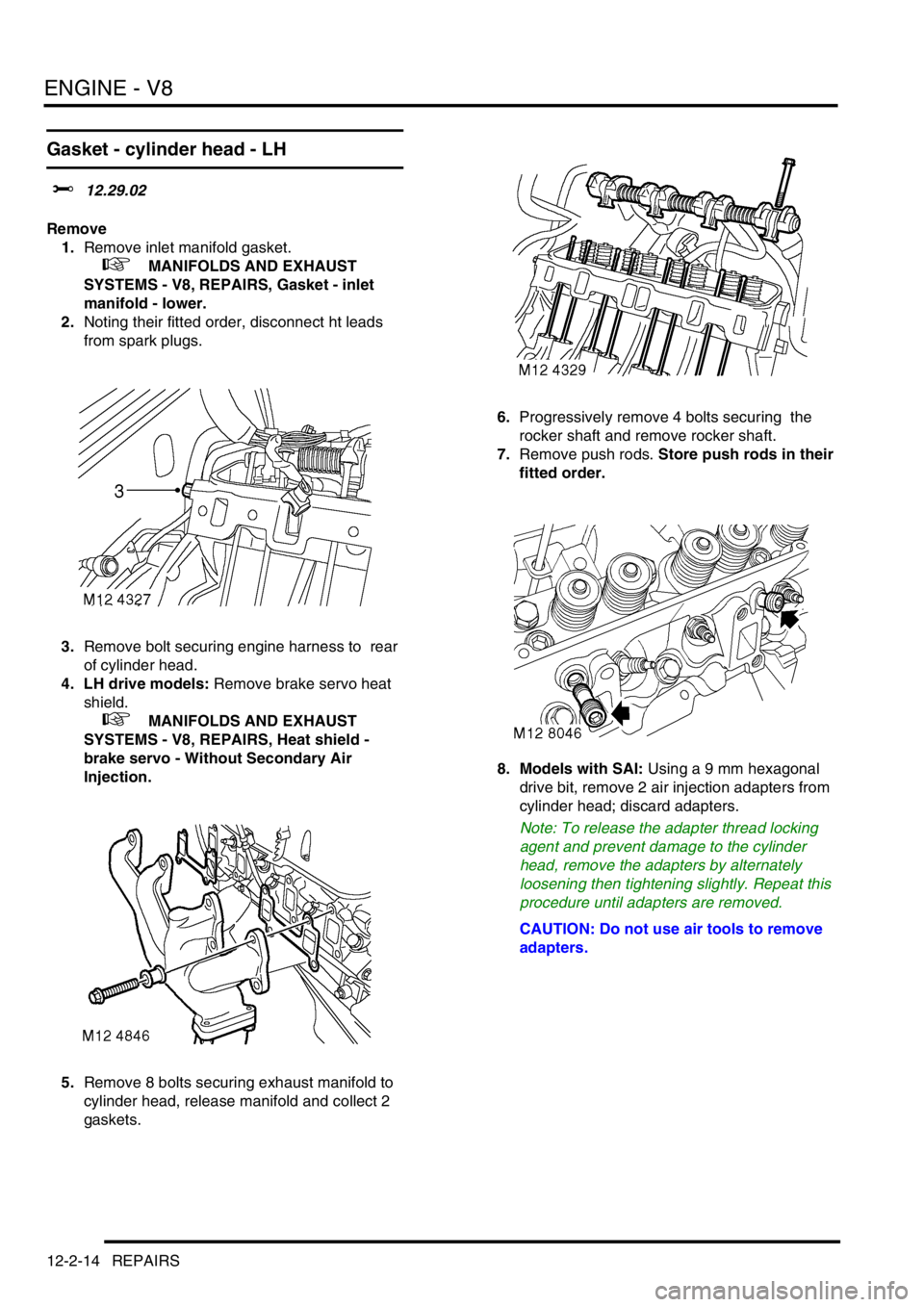
2.Noting their fitted order, disconnect ht leads
from spark plugs.
3.Remove bolt securing engine harness to rear
of cylinder head.
4. LH drive models: Remove brake servo heat
shield.
+ MANIFOLDS AND EXHAUST
SYSTEMS - V8, REPAIRS, Heat shield -
brake servo - Without Secondary Air
Injection.
5.Remove 8 bolts securing exhaust manifold to
cylinder head, release manifold and collect 2
gaskets.6.Progressively remove 4 bolts securing the
rocker shaft and remove rocker shaft.
7.Remove push rods. Store push rods in their
fitted order.
8. Models with SAI: Using a 9 mm hexagonal
drive bit, remove 2 air injection adapters from
cylinder head; discard adapters.
Note: To release the adapter thread locking
agent and prevent damage to the cylinder
head, remove the adapters by alternately
loosening then tightening slightly. Repeat this
procedure until adapters are removed.
CAUTION: Do not use air tools to remove
adapters.
Page 170 of 1529

ENGINE - V8
REPAIRS 12-2-15
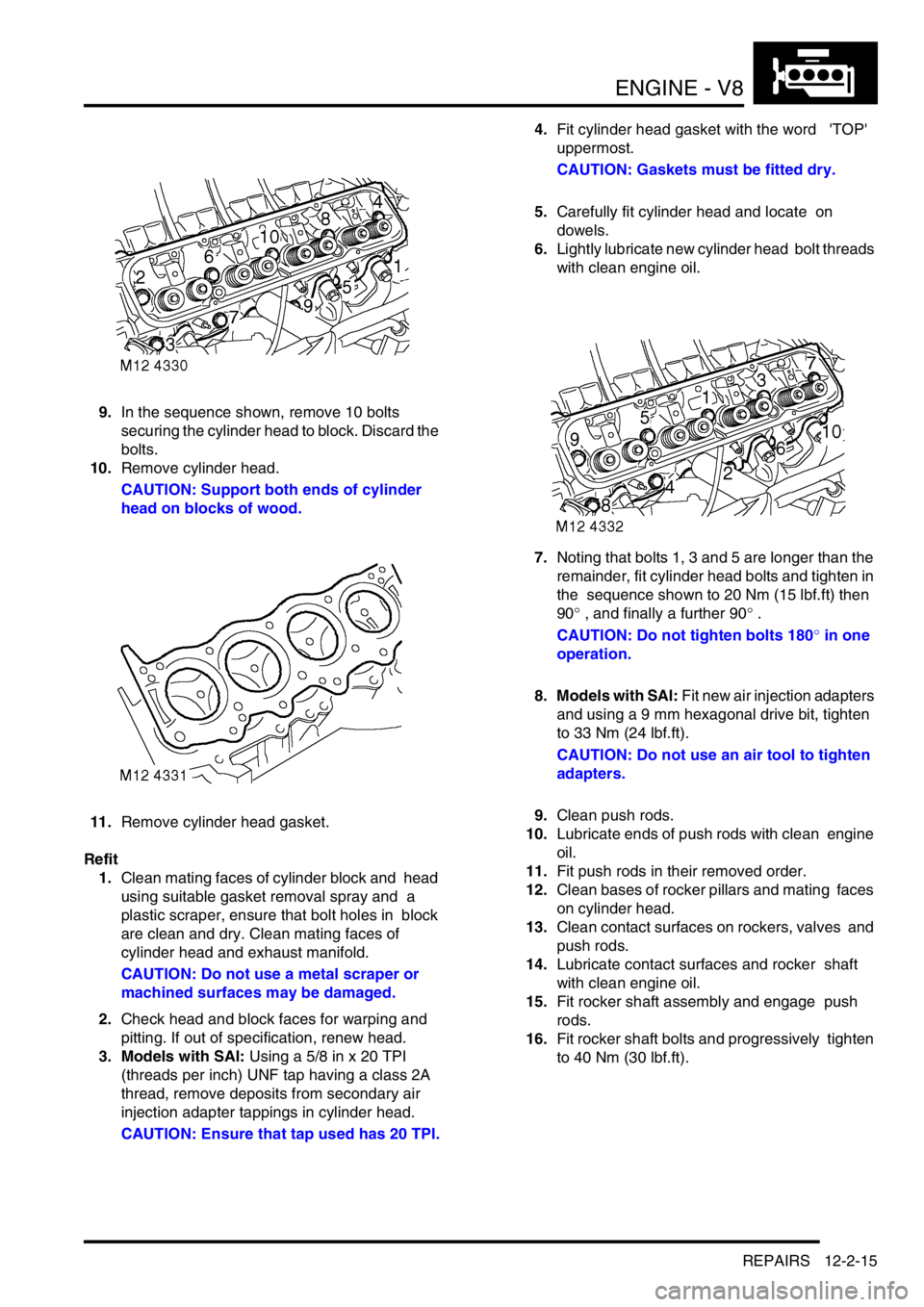
9.In the sequence shown, remove 10 bolts
securing the cylinder head to block. Discard the
bolts.
10.Remove cylinder head.
CAUTION: Support both ends of cylinder
head on blocks of wood.
11.Remove cylinder head gasket.
Refit
1.Clean mating faces of cylinder block and head
using suitable gasket removal spray and a
plastic scraper, ensure that bolt holes in block
are clean and dry. Clean mating faces of
cylinder head and exhaust manifold.
CAUTION: Do not use a metal scraper or
machined surfaces may be damaged.
2.Check head and block faces for warping and
pitting. If out of specification, renew head.
3. Models with SAI: Using a 5/8 in x 20 TPI
(threads per inch) UNF tap having a class 2A
thread, remove deposits from secondary air
injection adapter tappings in cylinder head.
CAUTION: Ensure that tap used has 20 TPI.4.Fit cylinder head gasket with the word 'TOP'
uppermost.
CAUTION: Gaskets must be fitted dry.
5.Carefully fit cylinder head and locate on
dowels.
6.Lightly lubricate new cylinder head bolt threads
with clean engine oil.
7.Noting that bolts 1, 3 and 5 are longer than the
remainder, fit cylinder head bolts and tighten in
the sequence shown to 20 Nm (15 lbf.ft) then
90° , and finally a further 90° .
CAUTION: Do not tighten bolts 180° in one
operation.
8. Models with SAI: Fit new air injection adapters
and using a 9 mm hexagonal drive bit, tighten
to 33 Nm (24 lbf.ft).
CAUTION: Do not use an air tool to tighten
adapters.
9.Clean push rods.
10.Lubricate ends of push rods with clean engine
oil.
11.Fit push rods in their removed order.
12.Clean bases of rocker pillars and mating faces
on cylinder head.
13.Clean contact surfaces on rockers, valves and
push rods.
14.Lubricate contact surfaces and rocker shaft
with clean engine oil.
15.Fit rocker shaft assembly and engage push
rods.
16.Fit rocker shaft bolts and progressively tighten
to 40 Nm (30 lbf.ft).
Page 171 of 1529

ENGINE - V8
12-2-16 REPAIRS
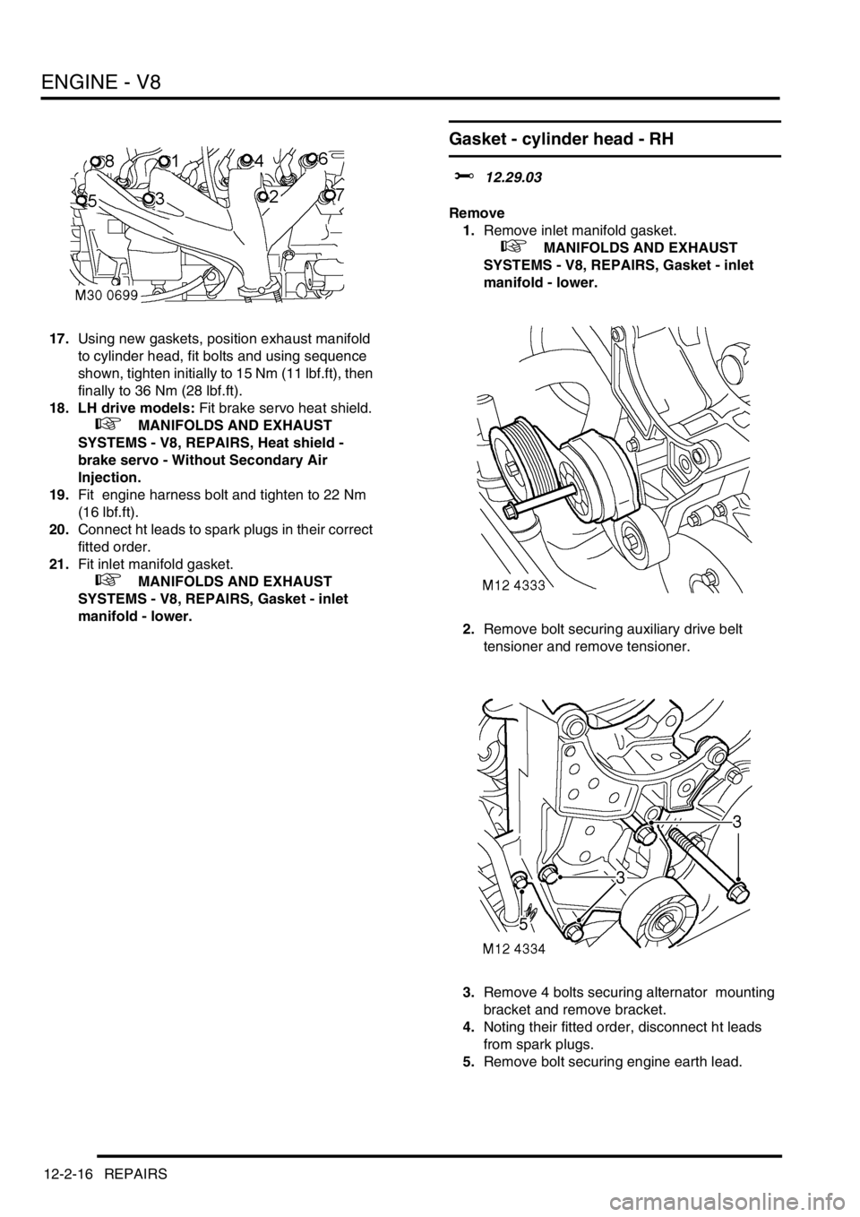
17.Using new gaskets, position exhaust manifold
to cylinder head, fit bolts and using sequence
shown, tighten initially to 15 Nm (11 lbf.ft), then
finally to 36 Nm (28 lbf.ft).
18. LH drive models: Fit brake servo heat shield.
+ MANIFOLDS AND EXHAUST
SYSTEMS - V8, REPAIRS, Heat shield -
brake servo - Without Secondary Air
Injection.
19.Fit engine harness bolt and tighten to 22 Nm
(16 lbf.ft).
20.Connect ht leads to spark plugs in their correct
fitted order.
21.Fit inlet manifold gasket.
+ MANIFOLDS AND EXHAUST
SYSTEMS - V8, REPAIRS, Gasket - inlet
manifold - lower.
Gasket - cylinder head - RH
$% 12.29.03
Remove
1.Remove inlet manifold gasket.
+ MANIFOLDS AND EXHAUST
SYSTEMS - V8, REPAIRS, Gasket - inlet
manifold - lower.
2.Remove bolt securing auxiliary drive belt
tensioner and remove tensioner.
3.Remove 4 bolts securing alternator mounting
bracket and remove bracket.
4.Noting their fitted order, disconnect ht leads
from spark plugs.
5.Remove bolt securing engine earth lead.
Page 172 of 1529

ENGINE - V8
REPAIRS 12-2-17
6. RH drive models: Remove brake servo heat
shield.
+ MANIFOLDS AND EXHAUST
SYSTEMS - V8, REPAIRS, Heat shield -
brake servo - Without Secondary Air
Injection.
7.Remove 8 bolts securing exhaust manifold to
cylinder head, release manifold and collect 2
gaskets.
8.Progressively remove 4 bolts securing the
rocker shaft and remove rocker shaft.
9.Remove push rods. Store push rods in their
fitted order. 10. Models with SAI: Using a 9 mm hexagonal
drive bit, remove 2 air injection adapters from
cylinder head; discard adapters.
Note: To release the adapter thread locking
agent and prevent damage to the cylinder
head, remove the adapters by alternately
loosening then tightening slightly. Repeat this
procedure until adapters are removed.
CAUTION: Do not use air tools to remove
adapters.
11.In the sequence shown, remove 10 bolts
securing the cylinder head to block. Discard the
bolts.
12.Remove cylinder head.
CAUTION: Support both ends of cylinder
head on blocks of wood.
Page 173 of 1529

ENGINE - V8
12-2-18 REPAIRS
13.Remove cylinder head gasket.
Refit
1.Clean mating faces of cylinder block and head
using suitable gasket removal spray and a
plastic scraper, ensure that bolt holes in block
are clean and dry. Clean mating faces of
cylinder head and exhaust manifold.
CAUTION: Do not use a metal scraper or
machined surfaces may be damaged.
2.Check head and block faces for warping and
pitting. If out of specification, renew head.
3. Models with SAI: Using a 5/8 in x 20 TPI
(threads per inch) UNF tap having a class 2A
thread, remove deposits from secondary air
injection adapter tappings in cylinder head.
CAUTION: Ensure that tap used has 20 TPI.
4.Fit cylinder head gasket with the word 'TOP'
uppermost.
CAUTION: Gasket must be fitted dry.
5.Carefully fit cylinder head and locate on
dowels.
6.Lightly lubricate new cylinder head bolt threads
with clean engine oil. 7.Noting that bolts 1, 3 and 5 are longer than the
remainder, fit bolts and tighten in the sequence
shown to 20 Nm (15 lbf.ft) then 90°, and finally
a further 90°.
CAUTION: Do not tighten bolts 180° in one
operation.
8. Models with SAI: Fit new air injection adapters
and using a 9 mm hexagonal drive bit, tighten
to 33 Nm (24 lbf.ft).
CAUTION: Do not use an air tool to tighten
adapters.
9.Clean push rods.
10.Lubricate ends of push rods with clean engine
oil.
11.Fit push rods in their removed order.
12.Clean bases of rocker pillars and mating faces
on cylinder head.
13.Clean contact surfaces on rockers, valves and
push rods.
14.Lubricate contact surfaces and rocker shaft
with clean engine oil.
15.Fit rocker shaft assembly and engage push
rods.
16.Fit rocker shaft bolts and progressively tighten
to 40 Nm (30 lbf.ft).
17.Position alternator mounting bracket, fit bolts
and tighten to 40 Nm (30 lbf.ft).
18.Position auxiliary drive belt tensioner, fit bolt
and tighten to 45 Nm (33 lbf.ft).
19.Connect ht leads to spark plugs in their fitted
order.
20. Using new gaskets, fit exhaust manifold to
cylinder head. Fit bolts and using sequence
shown, tighten initially to 15 Nm (11 lbf.ft), then
finally tighten to 36 Nm (28 lbf.ft).
21. RH drive models: Fit brake servo heat shield.
+ MANIFOLDS AND EXHAUST
SYSTEMS - V8, REPAIRS, Heat shield -
brake servo - Without Secondary Air
Injection.
22.Position engine earth lead, fit bolt and tighten to
22 Nm (16 lbf.ft).
23.Fit inlet manifold gasket.
+ MANIFOLDS AND EXHAUST
SYSTEMS - V8, REPAIRS, Gasket - inlet
manifold - lower.