1999 DODGE NEON air conditioning
[x] Cancel search: air conditioningPage 865 of 1200

POWERTRAIN CONTROL MODULE
The Powertrain Control Module (PCM) is a digital
computer containing a microprocessor (Fig. 2). The
PCM receives input signals from various switches
and sensors that are referred to as PCM Inputs.
Based on these inputs, the PCM adjusts various
engine and vehicle operations through devices that
are referred to as PCM Outputs.
PCM Inputs:
²Air Conditioning Controls
²Battery Voltage
²Battery Temperature Sensor
²Brake Switch
²Camshaft Position Sensor
²Crankshaft Position Sensor
²Engine Coolant Temperature Sensor
²Fuel Level Sensor
²Ignition Switch
²Intake Air Temperature Sensor
²Knock Sensor
²Manifold Absolute Pressure (MAP) Sensor
²Oxygen Sensors
²Power Steering Pressure Switch
²SCI Receive
²Speed Control Switches
²Throttle Position Sensor
²Transmission Park/Neutral Switch (automatic
transmission)
²Vehicle Speed Sensor
PCM Outputs:
²Air Conditioning WOT Relay
²Auto Shutdown (ASD) Relay
²Charging Indicator Lamp
²Data Link Connector
²Duty Cycle EVAP Canister Purge Solenoid
²EGR Solenoid
²Fuel Injectors
²Fuel Pump Relay²Generator Field
²Idle Air Control Motor
²Ignition Coils
²Malfunction Indicator (Check Engine) Lamp
²Radiator Fan Relay
²Speed Control Solenoids
²Tachometer
²Torque Convertor Clutch Solenoid
Based on inputs it receives, the PCM adjusts fuel
injector pulse width, idle speed, ignition spark
advance, ignition coil dwell and EVAP canister purge
operation. The PCM regulates the cooling fan, air
conditioning and speed control systems. The PCM
changes generator charge rate by adjusting the gen-
erator field. The PCM also performs diagnostics.
The PCM adjusts injector pulse width (air-fuel
ratio) based on the following inputs.
²Battery voltage
²Coolant temperature
²Intake air temperature
²Exhaust gas content (oxygen sensor)
²Engine speed (crankshaft position sensor)
²Manifold absolute pressure
²Throttle position
The PCM adjusts ignition timing based on the fol-
lowing inputs.
²Coolant temperature
²Intake air temperature
²Engine speed (crankshaft position sensor)
²Knock sensor
²Manifold absolute pressure
²Throttle position
²Transmission gear selection (park/neutral
switch)
The PCM also adjusts engine idle speed through
the idle air control motor based on the following
inputs.
²Air conditioning sense
²Battery voltage
²Battery temperature
²Brake switch
²Coolant temperature
²Engine speed (crankshaft position sensor)
²Engine run time
²Manifold absolute pressure
²Power steering pressure switch
²Throttle position
²Transmission gear selection (park/neutral
switch)
²Vehicle distance (speed)
The Auto Shutdown (ASD) and fuel pump relays
are mounted externally, but turned on and off by the
PCM.
The crankshaft position sensor signal is sent to the
PCM. If the PCM does not receive the signal within
approximately one second of engine cranking, it deac-
Fig. 2 Powertrain Control Module (PCM)
14 - 24 FUEL SYSTEMPL
DESCRIPTION AND OPERATION (Continued)
Page 866 of 1200

tivates the ASD relay and fuel pump relay. When
these relays deactivate, power is shut off from the
fuel injectors, ignition coils, heating element in the
oxygen sensors and the fuel pump.
The PCM contains a voltage converter that
changes battery voltage to a regulated 9 volts direct
current to power the camshaft position sensor, crank-
shaft position sensor and vehicle speed sensor. The
PCM also provides a 5 volt direct current supply for
the manifold absolute pressure sensor and throttle
position sensor.
AIR CONDITIONING PRESSURE TRANSDUCERÐ
PCM INPUT
The Powertrain Control Module (PCM) monitors
the A/C compressor discharge (high side) pressure
through the air conditioning pressure transducer.
The transducer supplies an input to the PCM. The
PCM engages the A/C compressor clutch if pressure
is sufficient for A/C system operation.
AUTOMATIC SHUTDOWN (ASD) SENSEÐPCM
INPUT
The ASD sense circuit informs the PCM when the
ASD relay energizes. A 12 volt signal at this input
indicates to the PCM that the ASD has been acti-
vated. This input is used only to sense that the ASD
relay is energized.
When energized, the ASD relay supplies battery
voltage to the fuel injectors, ignition coils and the
heating element in each oxygen sensor. If the PCM
does not receive 12 volts from this input after
grounding the ASD relay, it sets a Diagnostic Trouble
Code (DTC).
BATTERY VOLTAGEÐPCM INPUT
The PCM monitors the battery voltage input to
determine fuel injector pulse width and generator
field control.
If battery voltage is low the PCM will increase
injector pulse width (period of time that the injector
is energized).
BATTERY TEMPERATURE SENSORÐPCM INPUT
The PCM uses the temperature of the battery area
to control the charge rate. The signal is used to reg-
ulate the system voltage. The system voltage is
higher at cold temperatures and is gradually reduced
as temperature is increased.
BRAKE SWITCHÐPCM INPUT
When the brake switch is activated, the PCM
receives an input indicating that the brakes are
being applied. The brake switch is mounted on the
brake pedal support bracket.
CAMSHAFT POSITION SENSORÐPCM INPUT
The PCM determines fuel injection synchronization
and cylinder identification from inputs provided by
the camshaft position sensor (Fig. 3) or (Fig. 4) and
crankshaft position sensor. From the two inputs, the
PCM determines crankshaft position.
The camshaft position sensor attaches to the rear
of the cylinder head. A target magnet attaches to the
rear of the camshaft and indexes to the correct posi-
tion. The target magnet has four different poles
arranged in an asymmetrical pattern (Fig. 5). As the
target magnet rotates, the camshaft position sensor
senses the change in polarity (Fig. 6). The sensor out-
put switch switches from high (5.0 volts) to low (0.5
volts) as the target magnet rotates. When the north
pole of the target magnet passes under the sensor,
the output switches high. The sensor output switches
low when the south pole of the target magnet passes
underneath.
The sensor also acts as a thrust plate to control
camshaft endplay.
Fig. 3 Camshaft Position SensorÐSOHC
Fig. 4 Camshaft Position SensorÐDOHC
PLFUEL SYSTEM 14 - 25
DESCRIPTION AND OPERATION (Continued)
Page 872 of 1200

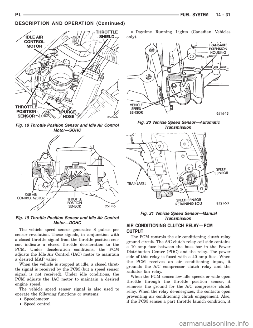
The vehicle speed sensor generates 8 pulses per
sensor revolution. These signals, in conjunction with
a closed throttle signal from the throttle position sen-
sor, indicate a closed throttle deceleration to the
PCM. Under deceleration conditions, the PCM
adjusts the Idle Air Control (IAC) motor to maintain
a desired MAP value.
When the vehicle is stopped at idle, a closed throt-
tle signal is received by the PCM (but a speed sensor
signal is not received). Under idle conditions, the
PCM adjusts the IAC motor to maintain a desired
engine speed.
The vehicle speed sensor signal is also used to
operate the following functions or systems:
²Speedometer
²Speed control²Daytime Running Lights (Canadian Vehicles
only).AIR CONDITIONING CLUTCH RELAYÐPCM
OUTPUT
The PCM controls the air conditioning clutch relay
ground circuit. The A/C clutch relay coil side contains
a 10 amp fuse between the buss bar in the Power
Distribution Center (PDC) and the relay. The power
side of this relay is fused with a 40 amp fuse. When
the PCM receives an air conditioning input, it
grounds the A/C compressor clutch relay and the
radiator fan relay.
When the PCM senses low idle speeds or wide open
throttle through the throttle position sensor, it
removes the ground for the A/C compressor clutch
relay. When the relay de-energizes, the contacts open
preventing air conditioning clutch engagement. Also,
if the PCM senses a part throttle launch condition, it
Fig. 18 Throttle Position Sensor and Idle Air Control
MotorÐSOHC
Fig. 19 Throttle Position Sensor and Idle Air Control
MotorÐDOHC
Fig. 20 Vehicle Speed SensorÐAutomatic
Transmission
Fig. 21 Vehicle Speed SensorÐManual
Transmission
PLFUEL SYSTEM 14 - 31
DESCRIPTION AND OPERATION (Continued)
Page 873 of 1200

disables the A/C compressor clutch for several sec-
onds.
The air conditioning clutch relay is located in the
PDC. The inside top of the PDC cover has a label
showing relay and fuse location.
AUTOMATIC SHUTDOWN RELAYÐPCM OUTPUT
The automatic shutdown (ASD) relay supplies bat-
tery voltage to the fuel injectors, electronic ignition
coil and the heating elements in the oxygen sensors.
A buss bar in the power distribution center (PDC)
supplies voltage to the solenoid side and contact side
of the relay. The ASD relay power circuit contains a
20 amp fuse between the buss bar in the PDC and
the relay. The fuse also protects the power circuit for
the fuel pump relay and pump. The fuse is located in
the PDC. Refer to Group 8W, Wiring Diagrams for
circuit information.
The PCM controls the relay by switching the
ground path for the solenoid side of the relay on and
off. The PCM turns the ground path off when the
ignition switch is in the Off position unless the 02
Heater Monitor test is being run. Refer to Group 25,
On-Board Diagnostics. When the ignition switch is in
the On or Crank position, the PCM monitors the
crankshaft position sensor and camshaft position sen-
sor signals to determine engine speed and ignition
timing (coil dwell). If the PCM does not receive the
crankshaft position sensor and camshaft position sen-
sor signals when the ignition switch is in the Run
position, it will de- energize the ASD relay.
The ASD relay is located in the PDC. The inside
top of the PDC cover has a label showing relay and
fuse location.
CHARGING SYSTEM INDICATOR LAMPÐPCM
OUTPUT
The PCM turns the instrument panel Charging
System Lamp on. Refer to Group 8C for charging sys-
tem information.
FUEL PUMP RELAYÐPCM OUTPUT
The fuel pump relay supplies battery voltage to the
fuel pump. A buss bar in the Power Distribution Cen-
ter (PDC) supplies voltage to the solenoid side and
contact side of the relay. The fuel pump relay power
circuit contains a 20 amp fuse between the buss bar
in the PDC and the relay. The fuse also protects the
power circuit for the Automatic Shutdown (ASD)
relay. The fuse is located in the PDC. Refer to Group
8W, Wiring Diagrams for circuit information.
The PCM controls the fuel pump relay by switch-
ing the ground path for the solenoid side of the relay
on and off. The PCM turns the ground path off when
the ignition switch is in the Off position. When the
ignition switch is in the On position, the PCM ener-gizes the fuel pump. If the crankshaft position sensor
does not detect engine rotation, the PCM de-ener-
gizes the relay after approximately one second.
The fuel pump relay is located in the PDC. The
inside top of the PDC cover has a label showing relay
and fuse location.
DUTY CYCLE EVAP PURGE SOLENOIDÐPCM
OUTPUT
The duty cycle EVAP purge solenoid regulates the
rate of vapor flow from the EVAP canister to the
throttle body. The powertrain control module oper-
ates the solenoid.
During the cold start warm-up period and the hot
start time delay, the PCM does not energize the sole-
noid. When de-energized, no vapors are purged.
The engine enters closed loop operation after it
reaches a specified temperature and the programmed
time delay ends. During closed loop operation, the
PCM energizes and de-energizes the solenoid 5 to 10
times per second, depending upon operating condi-
tions. The PCM varies the vapor flow rate by chang-
ing solenoid pulse width. Pulse width is the amount
of time the solenoid is energized.
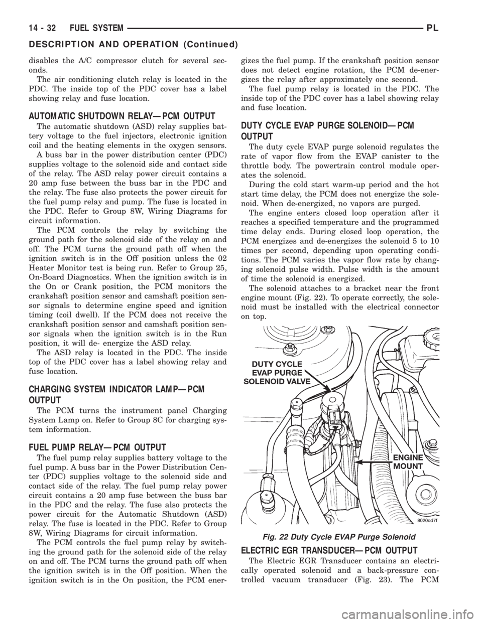
The solenoid attaches to a bracket near the front
engine mount (Fig. 22). To operate correctly, the sole-
noid must be installed with the electrical connector
on top.
ELECTRIC EGR TRANSDUCERÐPCM OUTPUT
The Electric EGR Transducer contains an electri-
cally operated solenoid and a back-pressure con-
trolled vacuum transducer (Fig. 23). The PCM
Fig. 22 Duty Cycle EVAP Purge Solenoid
14 - 32 FUEL SYSTEMPL
DESCRIPTION AND OPERATION (Continued)
Page 874 of 1200

operates the solenoid based on inputs from the multi-
port fuel injection system. The transducer and EGR
valve are serviced as an assembly.
When the PCM energizes the solenoid, vacuum
does not reach the transducer. Vacuum flows to the
transducer when the PCM de-energizes the solenoid.
When exhaust system back-pressure becomes high
enough, it fully closes a bleed valve in the vacuum
transducer. When the PCM de-energizes the solenoid
and back-pressure closes the transducer bleed valve,
vacuum flows through the transducer to operate the
EGR valve.
De-energizing the solenoid, but not fully closing the
transducer bleed hole (because of low back-pressure),
varies the strength of the vacuum signal applied to
the EGR valve. Varying the strength of the vacuum
signal changes the amount of EGR supplied to the
engine. This provides the correct amount of exhaust
gas recirculation for different operating conditions.
The transducer mounts to the clean air hose and
the EGR valve mount to the rear of the cylinder head
(Fig. 23).
GENERATOR FIELDÐPCM OUTPUT
The PCM regulates the charging system voltage
within a range of 12.9 to 15.0 volts. Refer to Group
8A for Battery system information and 8C for charg-
ing system information.
IDLE AIR CONTROL MOTORÐPCM OUTPUT
The Idle Air Control (IAC) motor is mounted on the
throttle body. The PCM operates the idle air control
motor (Fig. 24). The PCM adjusts engine idle speed
through the idle air control motor to compensate for
engine load, coolant temperature or barometric pres-
sure changes.
The throttle body has an air bypass passage that
provides air for the engine during closed throttle idle.The idle air control motor pintle protrudes into the
air bypass passage and regulates air flow through it.
The PCM adjusts engine idle speed by moving the
IAC motor pintle in and out of the bypass passage.
The adjustments are based on inputs the PCM
receives. The inputs are from the throttle position
sensor, crankshaft position sensor, coolant tempera-
ture sensor, MAP sensor, vehicle speed sensor and
various switch operations (brake, park/neutral, air
conditioning).
DATA LINK CONNECTOR
The data link connector (diagnostic connector)
links the DRB scan tool with the powertrain control
module (PCM). Refer to On-Board Diagnostics in the
General Diagnosis section of this group. The data
link connector is located inside the vehicle, under the
instrument panel, left of the steering column (Fig.
25).
Fig. 23 Electric EGR Backpressure TransducerÐ
Typical
Fig. 24 Idle Air Control Motor Air Bypass PassageÐ
Typical
Fig. 25 Data Link Connector
PLFUEL SYSTEM 14 - 33
DESCRIPTION AND OPERATION (Continued)
Page 876 of 1200

send incorrect signals. The PCM substitutes for the
incorrect signals with inputs from other sensors.
If the PCM detects active engine misfire severe
enough to cause catalyst damage, it flashes the MIL.
At the same time the PCM also sets a Diagnostic
Trouble Code (DTC).
For signals that can trigger the MIL (Check
Engine Lamp) refer to Group 25, On-Board
Dianostics.
SOLID STATE FAN RELAYÐPCM OUTPUT
The radiator fan runs when coolant temperature
and A/C system pressure demand cooling. The radia-
tor fan circuit contains a Solid State Fan Relay
(SSFR). Refer to the Group 8W for a circuit sche-
matic.
A 5 volt signal is supplied to the SSFR. The PCM
provides a pulsed ground for the SSFR. Depending
upon the amount of pulse on time, the SSFR puts out
a proportional voltage to the fan motor at the lower
speed. For instance, if the on time is 30 percent, then
the voltage to the fan motor will be 3.6 volts.
When engine coolant reaches approximately 99ÉC
(210ÉF) the PCM grounds the SSFR relay. When the
PCM grounds the relay it operates at a 30% duty
cycle and immediately ramps up to 100% duty cycle.
The PCM de-energizes the SSFR relay when coolant
temperature drops to approximately 93ÉC (199ÉF).
Also, when the air conditioning pressure switch
closes, the PCM grounds the SSFR. The air condi-
tioning switch closes at 285 psi610 psi. When air
conditioning pressure drops approximately 40 psi, the
pressure switch opens and the fan turns off.
The SSFR relay is located on the left front inner
frame just behind the radiator.
SPEED CONTROLÐPCM INPUT
The speed control system provides five separate
voltages (inputs) to the Powertrain Control Module
(PCM). The voltages correspond to the ON/OFF, SET,
RESUME and CANCEL.
The speed control ON voltage informs the PCM
that the speed control system has been activated.
The speed control SET voltage informs the PCM that
a fixed vehicle speed has been selected. The speed
control RESUME voltage indicates the previous fixed
speed is requested. The speed control CANCEL volt-
age tells the PCM to deactivate but retain set speed
in memory (same as depressing the brake pedal). The
speed control OFF voltage tells the PCM that the
speed control system has deactivated. Refer to Group
8H for more speed control information.
SCI RECEIVEÐPCM OUTPUT
SCI Receive is the serial data communication
receive circuit for the DRB scan tool. The Powertrain
Control Module (PCM) receives data from the DRB
through the SCI Receive circuit.
TACHOMETERÐPCM OUTPUT
The PCM operates the tachometer on the instru-
ment panel. The PCM calculates engine RPM from
the crankshaft position sensor input.
TORQUE CONVERTOR CLUTCH SOLENOIDÐPCM
OUTPUT
Three-speed automatic transaxles use a torque con-
verter clutch solenoid. The PCM controls the engage-
ment of the torque converter clutch through the
solenoid (Fig. 29). The torque converter clutch is
engaged up only in direct drive mode. Refer to Group
21 for transmission information.
DIAGNOSIS AND TESTING
VISUAL INSPECTIONÐSOHC
Before diagnosing or servicing the fuel injection
system, perform a visual inspection for loose, discon-
nected, or misrouted wires and hoses (Fig. 30). A
thorough visual inspection that includes the following
checks saves unnecessary test and diagnostic time.
(1) Inspect the battery connections. Clean corroded
terminals (Fig. 31).
(2) Check the 2 PCM 40-way connector for
stretched wires on pushed out terminals (Fig. 31).
Fig. 29 Torque Convertor Clutch Solenoid
PLFUEL SYSTEM 14 - 35
DESCRIPTION AND OPERATION (Continued)
Page 905 of 1200

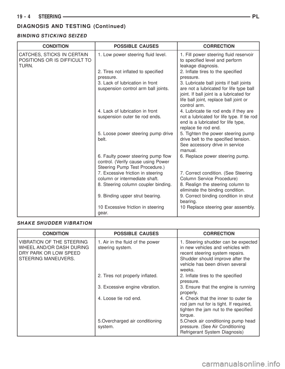
BINDING STICKING SEIZED
SHAKE SHUDDER VIBRATION
CONDITION POSSIBLE CAUSES CORRECTION
CATCHES, STICKS IN CERTAIN
POSITIONS OR IS DIFFICULT TO
TURN.1. Low power steering fluid level. 1. Fill power steering fluid reservoir
to specified level and perform
leakage diagnosis.
2. Tires not inflated to specified
pressure.2. Inflate tires to the specified
pressure.
3. Lack of lubrication in front
suspension control arm ball joints.3. Lubricate ball joints if ball joints
are not a lubricated for life type ball
joint. If ball joint is a lubricated for
life ball joint, replace ball joint or
control arm.
4. Lack of lubrication in front
suspension outer tie rod ends.4. Lubricate tie rod ends if they are
not a lubricated for life type. If tie rod
end is a lubricated for life type,
replace tie rod end.
5. Loose power steering pump drive
belt.5. Tighten the power steering pump
drive belt to the specified tension.
See accessory drive in service
manual.
6. Faulty power steering pump flow
control. (Verify cause using Power
Steering Pump Test Procedure.)6. Replace power steering pump.
7. Excessive friction in steering
column or intermediate shaft.7. Correct condition. (See Steering
Column Service Procedure)
8. Steering column coupler binding. 8. Realign the steering column to
eliminate the binding condition.
9. Binding upper strut bearing. 9. Correct binding condition in strut
bearing.
10 Excessive friction in steering
gear.10 Replace steering gear assembly.
CONDITION POSSIBLE CAUSES CORRECTION
VIBRATION OF THE STEERING
WHEEL AND/OR DASH DURING
DRY PARK OR LOW SPEED
STEERING MANEUVERS.1. Air in the fluid of the power
steering system.1. Steering shudder can be expected
in new vehicles and vehicles with
recent steering system repairs.
Shudder should improve after the
vehicle has been driven several
weeks.
2. Tires not properly inflated. 2. Inflate tires to the specified
pressure.
3. Excessive engine vibration. 3. Ensure that the engine is running
properly.
4. Loose tie rod end. 4. Check that the inner to outer tie
rod jam nut for is tight. If required,
tighten the jam nut to the specified
torque.
5.Overcharged air conditioning
system.5.Check air conditioning pump head
pressure. (See Air Conditioning
Refrigerant System Diagnosis)
19 - 4 STEERINGPL
DIAGNOSIS AND TESTING (Continued)
Page 1134 of 1200

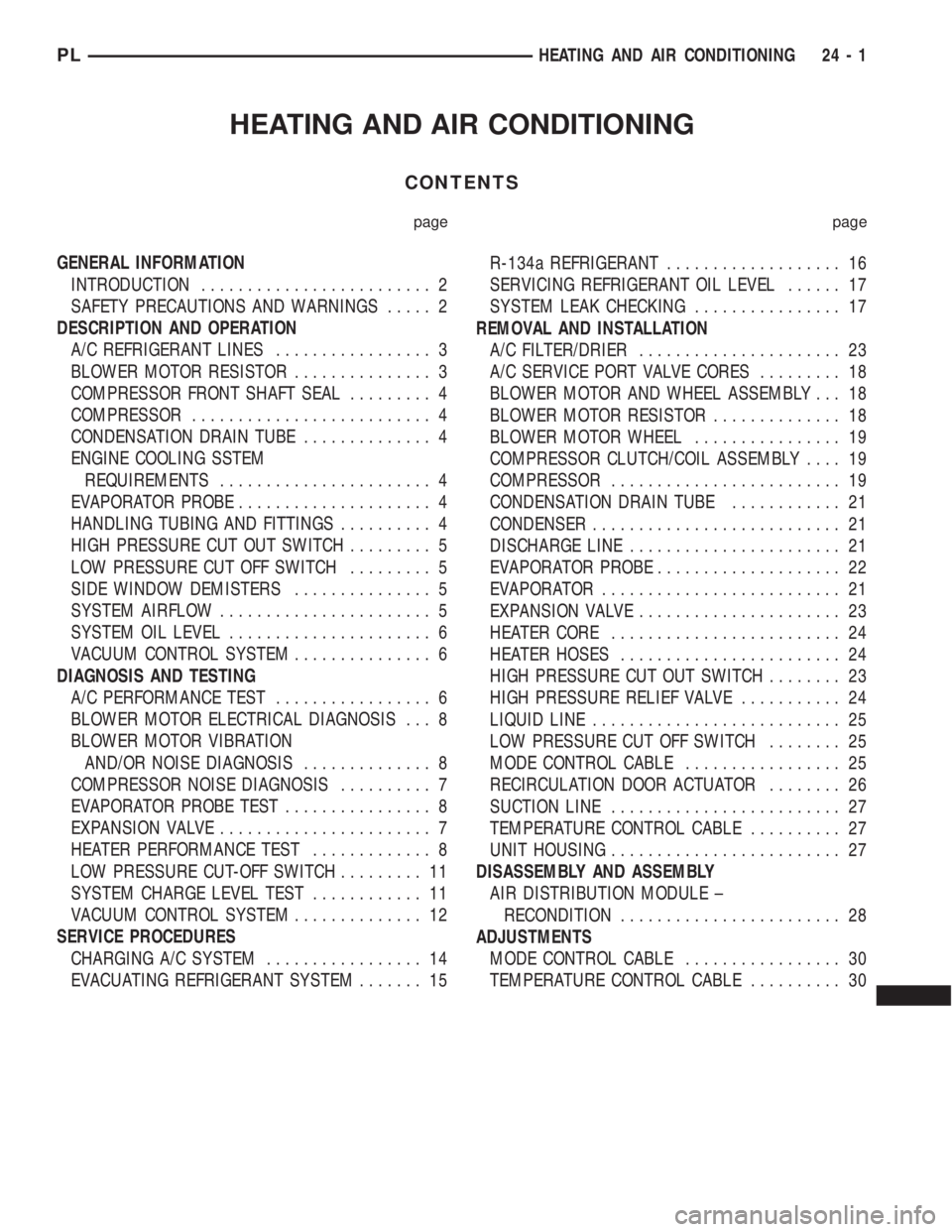
HEATING AND AIR CONDITIONING
CONTENTS
page page
GENERAL INFORMATION
INTRODUCTION......................... 2
SAFETY PRECAUTIONS AND WARNINGS..... 2
DESCRIPTION AND OPERATION
A/C REFRIGERANT LINES................. 3
BLOWER MOTOR RESISTOR............... 3
COMPRESSOR FRONT SHAFT SEAL......... 4
COMPRESSOR.......................... 4
CONDENSATION DRAIN TUBE.............. 4
ENGINE COOLING SSTEM
REQUIREMENTS....................... 4
EVAPORATOR PROBE..................... 4
HANDLING TUBING AND FITTINGS.......... 4
HIGH PRESSURE CUT OUT SWITCH......... 5
LOW PRESSURE CUT OFF SWITCH......... 5
SIDE WINDOW DEMISTERS............... 5
SYSTEM AIRFLOW....................... 5
SYSTEM OIL LEVEL...................... 6
VACUUM CONTROL SYSTEM............... 6
DIAGNOSIS AND TESTING
A/C PERFORMANCE TEST................. 6
BLOWER MOTOR ELECTRICAL DIAGNOSIS . . . 8
BLOWER MOTOR VIBRATION
AND/OR NOISE DIAGNOSIS.............. 8
COMPRESSOR NOISE DIAGNOSIS.......... 7
EVAPORATOR PROBE TEST................ 8
EXPANSION VALVE....................... 7
HEATER PERFORMANCE TEST............. 8
LOW PRESSURE CUT-OFF SWITCH......... 11
SYSTEM CHARGE LEVEL TEST............ 11
VACUUM CONTROL SYSTEM.............. 12
SERVICE PROCEDURES
CHARGING A/C SYSTEM................. 14
EVACUATING REFRIGERANT SYSTEM....... 15R-134a REFRIGERANT................... 16
SERVICING REFRIGERANT OIL LEVEL...... 17
SYSTEM LEAK CHECKING................ 17
REMOVAL AND INSTALLATION
A/C FILTER/DRIER...................... 23
A/C SERVICE PORT VALVE CORES......... 18
BLOWER MOTOR AND WHEEL ASSEMBLY . . . 18
BLOWER MOTOR RESISTOR.............. 18
BLOWER MOTOR WHEEL................ 19
COMPRESSOR CLUTCH/COIL ASSEMBLY.... 19
COMPRESSOR......................... 19
CONDENSATION DRAIN TUBE............ 21
CONDENSER........................... 21
DISCHARGE LINE....................... 21
EVAPORATOR PROBE.................... 22
EVAPORATOR.......................... 21
EXPANSION VALVE...................... 23
HEATER CORE......................... 24
HEATER HOSES........................ 24
HIGH PRESSURE CUT OUT SWITCH........ 23
HIGH PRESSURE RELIEF VALVE........... 24
LIQUID LINE........................... 25
LOW PRESSURE CUT OFF SWITCH........ 25
MODE CONTROL CABLE................. 25
RECIRCULATION DOOR ACTUATOR........ 26
SUCTION LINE......................... 27
TEMPERATURE CONTROL CABLE.......... 27
UNIT HOUSING......................... 27
DISASSEMBLY AND ASSEMBLY
AIR DISTRIBUTION MODULE ±
RECONDITION........................ 28
ADJUSTMENTS
MODE CONTROL CABLE................. 30
TEMPERATURE CONTROL CABLE.......... 30
PLHEATING AND AIR CONDITIONING 24 - 1