Page 1159 of 1200
RECIRCULATION DOOR ACTUATOR
The recirculation door actuator is a vacuum con-
trolled actuator used to control movement of the
recirculation door in air conditioned equipped vehi-
cles.
The instrument panel must be removed from the
vehicle to gain access to the recirculation door actua-
tor.
REMOVAL
(1) Remove instrument panel from vehicle. Refer
to Group 8E, Instrument Panel And Systems for
removal procedures.
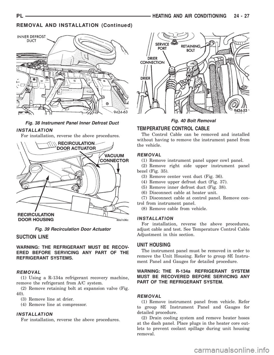
(2) Disconnect vacuum line from actuator (Fig. 39).
(3) Remove two nuts retaining vacuum actuator to
recirculation door housing.
(4) Disconnect actuator from recirc. door link.
(5) Remove recirculation door actuator from vehi-
cle.
Fig. 37 Instrument Panel Defrost Duct
24 - 26 HEATING AND AIR CONDITIONINGPL
REMOVAL AND INSTALLATION (Continued)
Page 1160 of 1200

INSTALLATION
For installation, reverse the above procedures.
SUCTION LINE
WARNING: THE REFRIGERANT MUST BE RECOV-
ERED BEFORE SERVICING ANY PART OF THE
REFRIGERANT SYSTEMS.
REMOVAL
(1) Using a R-134a refrigerant recovery machine,
remove the refrigerant from A/C system.
(2) Remove retaining bolt at expansion valve (Fig.
40).
(3) Remove line at drier.
(4) Remove line at compressor.
INSTALLATION
For installation, reverse the above procedures.
TEMPERATURE CONTROL CABLE
The Control Cable can be removed and installed
without having to remove the instrument panel from
the vehicle.
REMOVAL
(1) Remove instrument panel upper cowl panel.
(2) Remove right side upper instrument panel
bezel (Fig. 35).
(3) Remove center vent duct (Fig. 36).
(4) Remove upper defrost duct (Fig. 37).
(5) Remove inner defrost duct (Fig. 38).
(6) Disconnect cable at heater unit.
(7) Disconnect cable at control panel. Remove con-
trol from instrument panel.
(8) Remove cable from vehicle.
INSTALLATION
For installation, reverse the above procedures,
adjust cable and test. See Temperature Control Cable
Adjustment in this section.
UNIT HOUSING
The instrument panel must be removed in order to
remove the Unit Housing. Refer to group 8E Instru-
ment Panel and Gauges for detailed procedure.
WARNING: THE R-134a REFRIGERANT SYSTEM
MUST BE RECOVERED BEFORE SERVICING ANY
PART OF THE REFRIGERANT SYSTEM.
REMOVAL
(1) Remove instrument panel from vehicle. Refer
to group 8E Instrument Panel and Gauges for
detailed procedure.
(2) Drain cooling system and remove heater hoses
at the dash panel. Place plugs in the heater core out-
lets to prevent coolant spillage during unit housing
removal.
Fig. 40 Bolt RemovalFig. 38 Instrument Panel Inner Defrost Duct
Fig. 39 Recirculation Door Actuator
PLHEATING AND AIR CONDITIONING 24 - 27
REMOVAL AND INSTALLATION (Continued)
Page 1161 of 1200

(3) Using a refrigerant recovery machine, remove
the refrigerant from the A/C system, if equipped.
(4) Remove suction line at expansion valve. Place a
piece of tape over open refrigerant line to prevent
moisture and/or dirt from entering the line.
(5) Remove expansion valve from evaporator. Place
a piece of tape over open evaporator fitting to pre-
vent moisture and/or dirt from entering the evapora-
tor.
(6) Remove rubber drain tube extension from con-
densation drain tube.
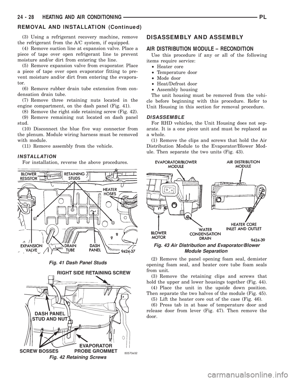
(7) Remove three retaining nuts located in the
engine compartment, on the dash panel (Fig. 41).
(8) Remove the right side retaining screw (Fig. 42).
(9) Remove remaining nut located on dash panel
stud.
(10) Disconnect the blue five way connector from
the plenum. Module wiring harness must be removed
with module.
(11) Remove assembly from the vehicle.
INSTALLATION
For installation, reverse the above procedures.
DISASSEMBLY AND ASSEMBLY
AIR DISTRIBUTION MODULE ± RECONDITION
Use this procedure if any or all of the following
items require service:
²Heater core
²Temperature door
²Mode door
²Heat/Defrost door
²Assembly housing
The unit housing must be removed from the vehi-
cle before beginning with this procedure. Refer to
Unit Housing in this section for removal procedure.
DISASSEMBLE
For RHD vehicles, the Unit Housing does not sep-
arate. It is a one piece unit and must be replaced as
a whole.
(1) Remove the clips and screws that hold the Air
Distribution Module to the Evaporator/Blower Mod-
ule. Then separate the two units (Fig. 43).
(2) Remove the panel opening foam seal, demister
opening foam seal, and heater core tube foam seals
from unit.
(3) Remove the retaining clips and screws that
hold the upper and lower housings together (Fig. 44).
(4) Place the unit in the upside down position.
Then separate the two halves of the module (Fig. 45).
(5) Lift the heater core out of the case (Fig. 46).
(6) Press tab in at base of temperature door and
release door from lever (Fig. 47). Then remove the
door.
Fig. 41 Dash Panel Studs
Fig. 42 Retaining Screws
Fig. 43 Air Distribution and Evaporator/Blower
Module Separation
24 - 28 HEATING AND AIR CONDITIONINGPL
REMOVAL AND INSTALLATION (Continued)
Page 1162 of 1200
(7) Press tab in at base of mode door and release
door from lever (Fig. 48).
(8) Remove Heat/Defrost door cam screw (Fig. 49).
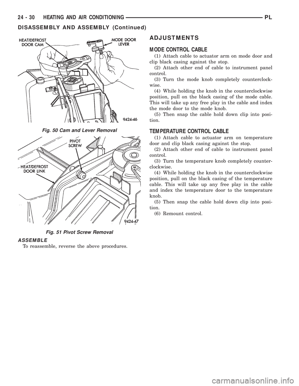
(9) Lift the cam and mode door lever off of the
housing (Fig. 50).(10) Remove the Heat/Defrost link pivot screw
(Fig. 51).
(11) Lift the Heat/Defrost link and the door as an
assembly. Then separate the link from the door.
Fig. 44 Retaining Clip Removal
Fig. 45 Case Separation
Fig. 46 Heater Core Removal
Fig. 47 Temperature Door Removal
Fig. 48 Mode Door Removal
Fig. 49 Cam Screw Removal
PLHEATING AND AIR CONDITIONING 24 - 29
DISASSEMBLY AND ASSEMBLY (Continued)
Page 1163 of 1200

ASSEMBLE
To reassemble, reverse the above procedures.
ADJUSTMENTS
MODE CONTROL CABLE
(1) Attach cable to actuator arm on mode door and
clip black casing against the stop.
(2) Attach other end of cable to instrument panel
control.
(3) Turn the mode knob completely counterclock-
wise.
(4) While holding the knob in the counterclockwise
position, pull on the black casing of the mode cable.
This will take up any free play in the cable and index
the mode door to the mode knob.
(5) Then snap the cable hold down clip into posi-
tion.
TEMPERATURE CONTROL CABLE
(1) Attach cable to actuator arm on temperature
door and clip black casing against the stop.
(2) Attach other end of cable to instrument panel
control.
(3) Turn the temperature knob completely counter-
clockwise.
(4) While holding the knob in the counterclockwise
position, pull on the black casing of the temperature
cable. This will take up any free play in the cable
and index the temperature door to the temperature
knob.
(5) Then snap the cable hold down clip into posi-
tion.
(6) Remount control.
Fig. 50 Cam and Lever Removal
Fig. 51 Pivot Screw Removal
24 - 30 HEATING AND AIR CONDITIONINGPL
DISASSEMBLY AND ASSEMBLY (Continued)
Page 1200 of 1200

GROUP TAB LOCATOR
INIntroduction
INaIntroduction
0Lubrication and Maintenance
2Suspension
3Differential and Driveline
5Brakes
6Clutch
6aClutch
7Cooling
8ABattery
8BStarting
8CCharging System
8CaCharging System
8DIgnition System
8EInstrument Panel and Systems
8EaInstrument Panel and Systems
8FAudio System
8GHorns
8HVehicle Speed Control System
8HaVehicle Speed Control System
8JTurn Signal and Flashers
8KWindshield Wipers and Washers
8KaWindshield Wipers and Washers
8LLamps
8LaLamps
8MRestraint System
8NElectrically Heated Systems
8NaElectrically Heated Systems
8PPower Door Locks
8QaImmobilizer System
8SPower Windows
8TPower Mirrors
8TaPower Mirrors
8UChime Warning/Reminder System
8WWiring Diagrams - LHD and RHD
9Engine
9aEngine
11Exhaust System and Intake Manifold
11aExhaust System and Intake Manifold
13Frame and Bumpers
13aFrame and Bumpers
14Fuel System
14aFuel System - 1.8L Engine
19Steering
19aSteering
21Transaxle
21aTransaxle
22Tires and Wheels
23Body
24Heating and Air Conditioning
25Emission Control Systems
25aEmission Control System - 1.8L Engine