Page 214 of 1200

must be replaced withonlythe recommended part
for adequate strength, performance and safety.
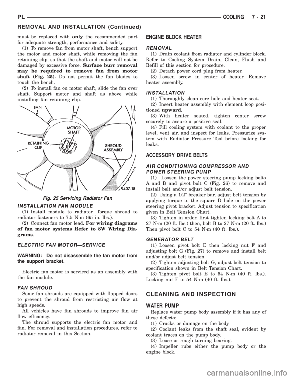
(1) To remove fan from motor shaft, bench support
the motor and motor shaft, while removing the fan
retaining clip, so that the shaft and motor will not be
damaged by excessive force.Surface burr removal
may be required to remove fan from motor
shaft (Fig. 25).Do not permit the fan blades to
touch the bench.
(2) To install fan on motor shaft, slide the fan over
shaft. Support motor and shaft as above while
installing fan retaining clip.
INSTALLATION FAN MODULE
(1) Install module to radiator. Torque shroud to
radiator fasteners to 7.5 N´m (65 in. lbs.).
(2) Connect fan motor lead.For wiring diagrams
of fan motor systems Refer to 8W Wiring Dia-
grams.
ELECTRIC FAN MOTORÐSERVICE
WARNING: Do not disassemble the fan motor from
the support bracket.
Electric fan motor is serviced as an assembly with
the fan module.
FAN SHROUD
Some fan shrouds are equipped with flapped doors
to prevent the shroud from restricting air flow at
high speeds.
All vehicles have fan shrouds to improve fan air
flow efficiency.
The shroud supports the electric fan motor and
fan. For removal and installation procedures, refer to
radiator removal in this Section.
ENGINE BLOCK HEATER
REMOVAL
(1) Drain coolant from radiator and cylinder block.
Refer to Cooling System Drain, Clean, Flush and
Refill of this section for procedure.
(2) Detach power cord plug from heater.
(3) Loosen screw in center of heater. Remove
heater assembly.
INSTALLATION
(1) Thoroughly clean core hole and heater seat.
(2) Insert heater assembly with element loop posi-
tionedupward.
(3) With heater seated, tighten center screw
securely to assure a positive seal.
(4) Fill cooling system with coolant to the proper
level, vent air, and inspect for leaks. Pressurize sys-
tem with Radiator Pressure Tool before looking for
leaks.
ACCESSORY DRIVE BELTS
AIR CONDITIONING COMPRESSOR AND
POWER STEERING PUMP
(1) Loosen the power steering pump locking bolts
A and B and pivot bolt C (Fig. 26) to remove and
install belt and/or adjust belt tension.
(2) Using a 1/2º breaker bar, adjust belt tension by
applying torque to the square D hole on the power
steering pivot bracket. Adjust tension to specification
given in Belt Tension Chart.
(3) Tighten in order, first tighten locking bolt A to
27 N´m (20 ft. lbs.) then, bolt B to 27 N´m (20 ft. lbs.)
Then pivot bolt C to 54 N´m (40 ft. lbs.).
GENERATOR BELT
(1) Loosen pivot bolt E then locking nut F and
adjusting bolt G (Fig. 27) to remove and install belt
and/or adjust belt tension.
(2) Tighten adjusting bolt G, adjust belt tension to
specification shown in Belt Tension Chart.
(3) Tighten pivot bolt E to 54 N´m (40 ft. lbs.).
Locking nut F to 54 N´m (40 ft. lbs.).
CLEANING AND INSPECTION
WATER PUMP
Replace water pump body assembly if it has any of
these defects:
(1) Cracks or damage on the body.
(2) Coolant leaks from the shaft seal, evident by
coolant traces on the pump body.
(3) Loose or rough turning bearing.
(4) Impeller rubs either the pump body or the
engine block.
Fig. 25 Servicing Radiator Fan
PLCOOLING 7 - 21
REMOVAL AND INSTALLATION (Continued)
Page 392 of 1200

WIRING DIAGRAMS
CONTENTS
page page
AIR CONDITIONING-HEATER.......... 8W-42-1
AIRBAG SYSTEM................... 8W-43-1
ANTI-LOCK BRAKES................. 8W-35-1
AUDIO SYSTEMS................... 8W-47-1
CHARGING SYSTEM................. 8W-20-1
COMPONENT INDEX................. 8W-02-1
CONNECTOR/GROUND LOCATIONS..... 8W-90-1
CONNECTOR PIN-OUTS.............. 8W-80-1
FRONT LIGHTING................... 8W-50-1
FUEL/IGNITION SYSTEMS............ 8W-30-1
FUSE BLOCK....................... 8W-11-1
GENERAL INFORMATION............. 8W-01-1
GROUND DISTRIBUTION............. 8W-15-1
HORN/CIGAR LIGHTER............... 8W-41-1INSTRUMENT CLUSTER.............. 8W-40-1
INTERIOR LIGHTING................. 8W-44-1
POWER DISTRIBUTION.............. 8W-10-1
POWER DOOR LOCKS............... 8W-61-1
POWER MIRRORS.................. 8W-62-1
POWER SUNROOF.................. 8W-64-1
POWER WINDOWS.................. 8W-60-1
REAR LIGHTING.................... 8W-51-1
REAR WINDOW DEFOGGER........... 8W-48-1
SPLICE INFORMATION............... 8W-70-1
SPLICE LOCATIONS................. 8W-95-1
STARTING SYSTEM................. 8W-21-1
TURN SIGNALS..................... 8W-52-1
WIPERS........................... 8W-53-1
PLWIRING DIAGRAMS 8W - 1
Page 512 of 1200

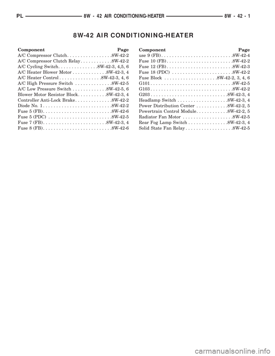
8W-42 AIR CONDITIONING-HEATER
Component Page
A/C Compressor Clutch.................8W-42-2
A/C Compressor Clutch Relay............8W-42-2
A/C Cycling Switch...............8W-42-3, 4,5, 6
A/C Heater Blower Motor.............8W-42-3, 4
A/C Heater Control................8W-42-3, 4, 6
A/C High Pressure Switch..............8W-42-5
A/C Low Pressure Switch.............8W-42-5, 6
Blower Motor Resistor Block...........8W-42-3, 4
Controller Anti-Lock Brake..............8W-42-2
Diode No. 1..........................8W-42-2
Fuse 5 (FB)..........................8W-42-6
Fuse 5 (PDC)........................8W-42-5
Fuse 7 (FB)........................8W-42-3, 4
Fuse 8 (FB)..........................8W-42-6Component Page
use 9 (FB)...........................8W-42-4
Fuse 10 (FB).........................8W-42-2
Fuse 12 (FB).........................8W-42-3
Fuse 18 (PDC).......................8W-42-2
Fuse Block....................8W-42-2, 3, 4, 6
G101...............................8W-42-5
G103...............................8W-42-2
G203.............................8W-42-3, 4
Headlamp Switch...................8W-42-3, 4
Power Distribution Center............8W-42-2, 5
Powertrain Control Module............8W-42-2, 5
Radiator Fan Motor...................8W-42-5
Rear Fog Lamp Switch...............8W-42-3, 4
Solid State Fan Relay..................8W-42-5
PL8W - 42 AIR CONDITIONING-HEATER 8W - 42 - 1
Page 513 of 1200
18
36
35
3233
POWER
DISTRIBUTION
CENTER
15A
FUSE
10
10
30BLOCK FUSE
F12
20
DG/WT
F12
20
DG/WT
F12
18
DG/WT
Z1
18
BK
G103CLUTCH COMPRESSOR
A/C
C1
64
POWERTRAIN
CONTROL
MODULE S109
C28
18
DB/OR
A/C
COMPRESSOR
CLUTCH
RELAY
CONTROL
ST-RUN A21
10A
FUSE
18
17
BATT A0
1
2
A/C
COMPRESSOR
CLUTCH
RELAY
DIODE
C3 16DB/BK
18BK Z1
71
DB/BK16 C3
A17
12
RD/BK
9
BRAKE ANTI-LOCK
CONTROLLER
NO. 1
6C101
(8W-10-5)
(8W-10-6) (8W-11-14)(8W-11-2)
(8W-11-3)
(8W-11-4)
(8W-15-5)
(8W-15-6) (8W-30-12) (8W-11-14)
(8W-10-14) (8W-10-9)
(8W-10-5)
(8W-35-2)
8W - 42 - 2 8W-42 AIR CONDITIONING-HEATERPL
J988W-18284
Page 514 of 1200
C4
14
TNC5
14
LGC6
14
LBC7
14
BK/TN
BLOCK RESISTOR
MOTOR
BLOWER
C2
22
DB/YL
C2
22
DB/YL1
C206
G203
Z8
14
BK/VT
S204
4A
FUSE
12
7
27
32
25A
FUSE
7
12
BLOCK FUSE
1
BATT F33
C1
14
DG
C7
14
BK/TN 4
C206
6C206
RUN A22
FUSE
BLOCK
1
2
5124
SWITCH
OUTPUT2
10
MOTOR BLOWER
HEATER
A/C
A/C
CYCLING
SWITCH
C2256
S314
TOZ8
18
BK/VT
M
C1 14DGE1
20
TN
E2
20
OR
S210
14 HI-A/C 13 M2-A/C
12 M1-A/C
11 LOW-A/C
10 BLOWER-LOW
9 BLOWER-M1
8 BLOWER-M2
7 BLOWER-HI
6 DEF
5 DEF/FLOOR (MIX) 2 PANEL 0 OFF
3 BI-LEVEL
4 FLOOR (HEAT)
ILLUMINATION
A/C
HEATER
CONTROL
10
9
8
70
11
12
13
14
23
4
5
6MODE
SWITCH
SWITCH BLOWER
73 4 5
1
26
3
6
E2 20OR
MODE
2 HEAD 1 PARK
0 OFF
HEADLAMP
SWITCH
-EXPORT) (BUILT-UP
SWITCH
LAMP
FOG
REAR
(8W-15-9) (8W-42-6)(8W-11-7)
(8W-10-8)
(8W-11-2)
(8W-11-3) (8W-11-2)
(8W-11-3)
(8W-11-12)
(8W-11-17)
(8W-11-18)
(8W-15-9)(8W-11-17)
(8W-11-18)(8W-50-2)
(8W-50-3)
(8W-51-11)
PL8W-42 AIR CONDITIONING-HEATER
LHD8W - 42 - 3
8285J988W-1
Page 515 of 1200
C4
14
TNC5
14
LGC6
14
LBC7
14
BK/TN
BLOCK RESISTOR
MOTOR
BLOWER
C2
22
DB/YL
C2
22
DB/YL1
C206
G203
Z8
14
BK/VT
S204
4A
FUSE
9
7
27
29
25A
FUSE
7
9
BLOCK FUSE
1
BATT F33
C1
14
DG
C7
14
BK/TN 4
C206
6C206
RUN A22
FUSE
BLOCK
1
2
5124
SWITCH
OUTPUT2
10
MOTOR BLOWER
HEATER
A/C
A/C
CYCLING
SWITCH
C2256
S314
TOZ8
18
BK/VT
M
C1 14DGE1
20
TN
E2
20
OR
S210
14 HI-A/C 13 M2-A/C
12 M1-A/C
11 LOW-A/C
10 BLOWER-LOW
9 BLOWER-M1
8 BLOWER-M2
7 BLOWER-HI
6 DEF
5 DEF/FLOOR (MIX) 2 PANEL 0 OFF
3 BI-LEVEL
4 FLOOR (HEAT)
ILLUMINATION
A/C
HEATER
CONTROL
10
9
8
70
11
12
13
14
23
4
5
6MODE
SWITCH
SWITCH BLOWER
73 4 5
1
26
3
6
E2 20OR
MODE
2 HEAD 1 PARK
0 OFF
HEADLAMP
SWITCH
-EXPORT) (BUILT-UP
SWITCH
LAMP
FOG
REAR
(8W-15-9) (8W-42-6)(8W-11-9)
(8W-10-8)
(8W-11-4) (8W-11-4)
(8W-11-13)
(8W-11-19)
(8W-15-9)(8W-11-19)(8W-50-4)
(8W-51-11)
8W - 42 - 4 8W-42 AIR CONDITIONING-HEATER
RHDPL
J988W-18286
Page 516 of 1200
30A
FUSE
5
5 6
BATT A0
POWER
DISTRIBUTION
CENTER
1
2A16
14
GY
RELAY FAN
STATE
SOLID
C2
18
K173
20
DG
K173
20
LG
13C160
Z1
18
BK
S111
Z1
14
BK
C25
14
LG
Z1
14
BK
G101
S108
POWERTRAIN
CONTROL
MODULE MOTOR FAN
RADIATOR
4
13
BR/OR18 C20
DB/OR22 C21
A/C
HIGH
PRESSURE
SWITCH A/C
LOW
PRESSURE
SWITCH
C2
38
DB/OR20 C21
C2063
2
1
2
1
C1605
SENSE SWITCHA/C
BR/OR20 C20
DB/WT20 C22
DB/OR22 C21
1
2
A/C
CYCLING
SWITCH
RADIATOR
FAN
PULSE
CONTROLA/C
CYCLING
SWITCH
OUTPUT
2C101
FUSED
B(+)
RELAY
CONTROL GROUNDRELAY
OUTPUT
RADIATOR
FAN
MOTOR
21
ATX MTX
M
MM
(8W-10-12)(8W-10-5)
(8W-10-6)
(8W-15-2)
(8W-15-3)
(8W-15-2)
(8W-15-3) (8W-15-2)
(8W-15-3)
(8W-30-12) (8W-10-5)
(8W-42-6)
PL8W-42 AIR CONDITIONING-HEATER 8W - 42 - 5
8287J988W-1
Page 517 of 1200
RUN A22
5
25
10A
FUSE
5
FUSED
IGN.
(RUN)
SWITCH CYCLING
A/C
C2
22
DB/YL
C2
22
DB/YL
F20
20
WT
F20
22
WT
2C206
2
MODE
SWITCH
OUTPUTA/C
CYCLING
SWITCH
OUTPUT
C21
22
DB/OR
3C206
13
1C206
S211
C21
20
DB/OR
BLOCK FUSE
C21
22
DB/OR
F20
22
WT
62
SWITCH PRESSURE
LOW
A/C
8FUSE10A
288
RUN A22
WT20 F20
RHD LHD
A/C
HEATER
CONTROL
2C101
(8W-11-13)
(8W-11-12)
(8W-11-13)(8W-11-2)
(8W-11-3)
(8W-11-4)
(8W-42-5) (8W-10-8) (8W-10-8)
(8W-11-12)
(8W-42-3)
(8W-42-4)
8W - 42 - 6 8W-42 AIR CONDITIONING-HEATERPL
J988W-18288