Page 587 of 1659
DIAGNOSTIC PROCEDURE 9
Security indicator check
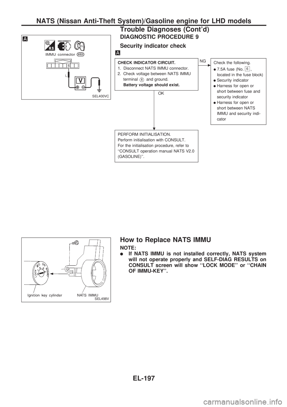
CHECK INDICATOR CIRCUIT.
1. Disconnect NATS IMMU connector.
2. Check voltage between NATS IMMU
terminal
V6and ground.
Battery voltage should exist.
OK
cNG
Check the following.
l7.5A fuse (No.6,
located in the fuse block)
lSecurity indicator
lHarness for open or
short between fuse and
security indicator
lHarness for open or
short between NATS
IMMU and security indi-
cator
PERFORM INITIALISATION.
Perform initialisation with CONSULT.
For the initialisation procedure, refer to
``CONSULT operation manual NATS V2.0
(GASOLINE)''.
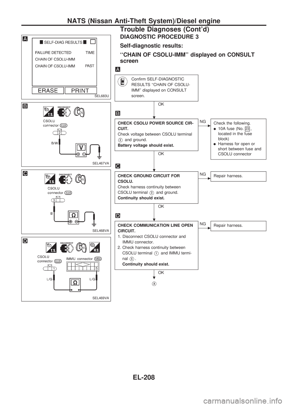
How to Replace NATS IMMU
NOTE:
lIf NATS IMMU is not installed correctly, NATS system
will not operate properly and SELF-DIAG RESULTS on
CONSULT screen will show ``LOCK MODE'' or ``CHAIN
OF IMMU-KEY''.
SEL400VC
SEL498V
.
NATS (Nissan Anti-Theft System)/Gasoline engine for LHD models
Trouble Diagnoses (Cont'd)
EL-197
Page 596 of 1659

SYMPTOM CHART
SymptomDisplayed ``SELF-DIAG
RESULTS'' on CONSULT
screenDiagnostic Procedure
(Reference page)System
(Malfunctioning part or mode)
lNo lighting/lighting of secu-
rity indicator with ignition
switch in ``ON'' position
lHard to start engineIMMU PROCEDURE 1
(EL-207)IMMU
lLighting of security indica-
tor with ignition switch in
``ON'' position
lHard to start engineCSOLU PROCEDURE 2
(EL-207)CSOLU
CHAIN OF CSOLU-IMM PROCEDURE 3
(EL-208)Open circuit in ignition line of CSOLU
Open circuit in ground line of CSOLU
Open or short circuit in communication line
between IMMU and CSOLU
IMMU
CSOLU
KEY ID
[NO INPUT]PROCEDURE 5
(EL-211)Open or short circuit in communication line
between ANT/AMP and IMMU
Open circuit in power source line of ANT/
AMP circuit
Open circuit in ground of ANT/AMP circuit
Malfunction of key ID chip
IMMU
Antenna amp.
ID DISCORD, IMM-CSLU PROCEDURE 6
(EL-213)System initialisation has not yet been com-
pleted.
CSOLU
IMMU
lHard to start engine
lLighting of security indica-
tor with ignition switch in
``ON'' position (See note)KEY ID
[DIFFERENCE]PROCEDURE 4
(EL-210)Unregistered key
lHard to start engine
lNo lighting of security indi-
cator.
lImpossible to proceed with
the CONSULT diagnosesAfter touch ``START'',
CONSULT screen dis-
plays ``IMPOSSIBLE TO
PROCEED''.PROCEDURE 7
(EL-214)Open or short circuit in communication line
between IMMU and CONSULT data link
connector
Open or short circuit in antenna amp. power
source circuit between IMMU and antenna
amp.
Open circuit in power source line of IMMU
circuit
Open circuit in ignition line of IMMU circuit
Open circuit in ground line of IMMU circuit
IMMU
lNATS security ind. does
not blink with ignition
switch in ``OFF'' or ``ACC''.
lEngine starts properly.Ð PROCEDURE 8
(EL-216)NATS security ind.
Open circuit between fuse and NATS IMMU
Continuation of initialisation mode
NOTE: NATS security ind. may light off for 1 minute after ignition switch is turned to ``OFF'' position.
NATS (Nissan Anti-Theft System)/Diesel engine
Trouble Diagnoses (Cont'd)
EL-206
Page 598 of 1659
DIAGNOSTIC PROCEDURE 3
Self-diagnostic results:
``CHAIN OF CSOLU-IMM'' displayed on CONSULT
screen
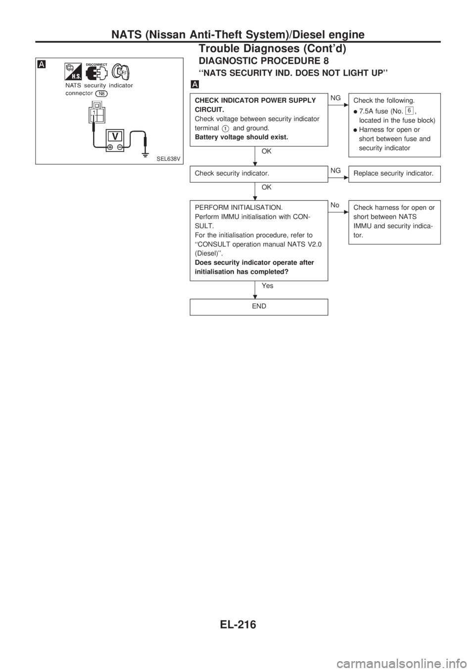
Confirm SELF-DIAGNOSTIC
RESULTS ``CHAIN OF CSOLU-
IMM'' displayed on CONSULT
screen.
OK
CHECK CSOLU POWER SOURCE CIR-
CUIT.
Check voltage between CSOLU terminal
V2and ground.
Battery voltage should exist.
OK
cNG
Check the following.
l10A fuse (No.23,
located in the fuse
block)
lHarness for open or
short between fuse and
CSOLU connector
CHECK GROUND CIRCUIT FOR
CSOLU.
Check harness continuity between
CSOLU terminal
V3and ground.
Continuity should exist.
OK
cNG
Repair harness.
CHECK COMMUNICATION LINE OPEN
CIRCUIT.
1. Disconnect CSOLU connector and
IMMU connector.
2. Check harness continuity between
CSOLU terminal
V1and IMMU termi-
nal
V5.
Continuity should exist.
OK
cNG
Repair harness.
VA
SEL683U
SEL467VA
SEL468VA
SEL469VA
.
.
.
.
NATS (Nissan Anti-Theft System)/Diesel engine
Trouble Diagnoses (Cont'd)
EL-208
Page 605 of 1659
VA
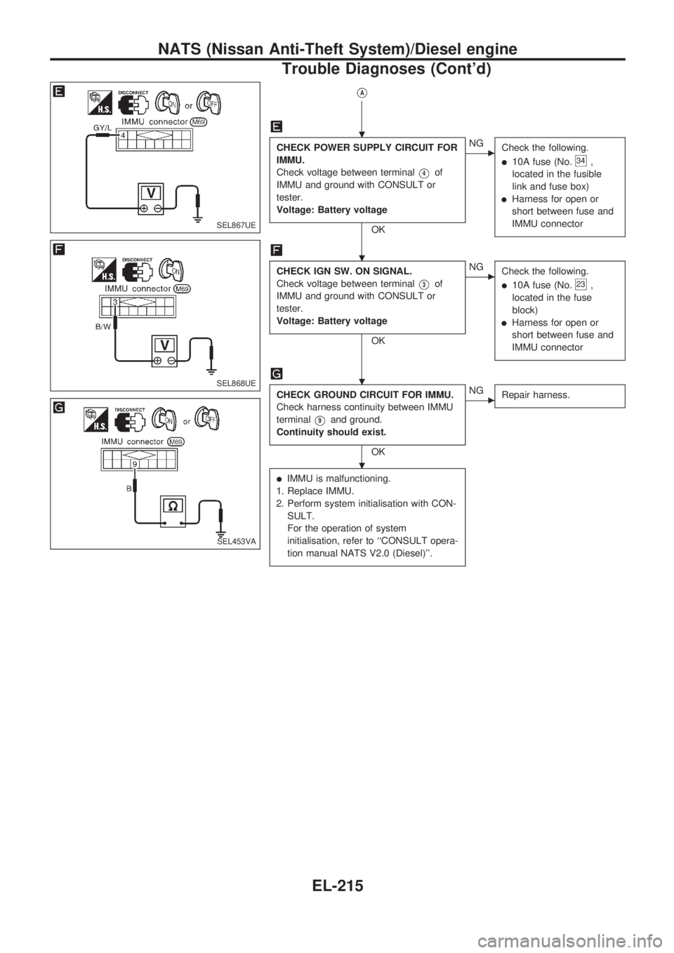
CHECK POWER SUPPLY CIRCUIT FOR
IMMU.
Check voltage between terminal
V4of
IMMU and ground with CONSULT or
tester.
Voltage: Battery voltage
OK
cNG
Check the following.
l10A fuse (No.34,
located in the fusible
link and fuse box)
lHarness for open or
short between fuse and
IMMU connector
CHECK IGN SW. ON SIGNAL.
Check voltage between terminal
V3of
IMMU and ground with CONSULT or
tester.
Voltage: Battery voltage
OK
cNG
Check the following.
l10A fuse (No.23,
located in the fuse
block)
lHarness for open or
short between fuse and
IMMU connector
CHECK GROUND CIRCUIT FOR IMMU.
Check harness continuity between IMMU
terminal
V9and ground.
Continuity should exist.
OK
cNG
Repair harness.
lIMMU is malfunctioning.
1. Replace IMMU.
2. Perform system initialisation with CON-
SULT.
For the operation of system
initialisation, refer to ``CONSULT opera-
tion manual NATS V2.0 (Diesel)''.
SEL867UE
SEL868UE
SEL453VA
.
.
.
.
NATS (Nissan Anti-Theft System)/Diesel engine
Trouble Diagnoses (Cont'd)
EL-215
Page 606 of 1659
DIAGNOSTIC PROCEDURE 8
``NATS SECURITY IND. DOES NOT LIGHT UP''
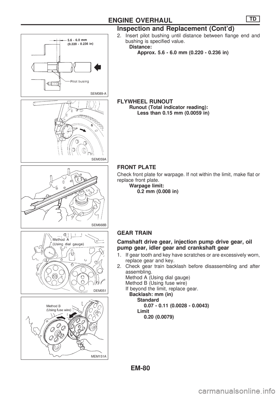
CHECK INDICATOR POWER SUPPLY
CIRCUIT.
Check voltage between security indicator
terminal
V1and ground.
Battery voltage should exist.
OK
cNG
Check the following.
l7.5A fuse (No.6,
located in the fuse block)
lHarness for open or
short between fuse and
security indicator
Check security indicator.
OK
cNG
Replace security indicator.
PERFORM INITIALISATION.
Perform IMMU initialisation with CON-
SULT.
For the initialisation procedure, refer to
``CONSULT operation manual NATS V2.0
(Diesel)''.
Does security indicator operate after
initialisation has completed?
Yes
cNo
Check harness for open or
short between NATS
IMMU and security indica-
tor.
END
SEL638V.
.
.
NATS (Nissan Anti-Theft System)/Diesel engine
Trouble Diagnoses (Cont'd)
EL-216
Page 725 of 1659
2. Insert pilot bushing until distance between flange end and
bushing is specified value.
Distance:
Approx. 5.6 - 6.0 mm (0.220 - 0.236 in)
FLYWHEEL RUNOUT
Runout (Total indicator reading):
Less than 0.15 mm (0.0059 in)
FRONT PLATE
Check front plate for warpage. If not within the limit, make flat or
replace front plate.
Warpage limit:
0.2 mm (0.008 in)
GEAR TRAIN
Camshaft drive gear, injection pump drive gear, oil
pump gear, idler gear and crankshaft gear
1. If gear tooth and key have scratches or are excessively worn,
replace gear and key.
2. Check gear train backlash before disassembling and after
assembling.
Method A (Using dial gauge)
Method B (Using fuse wire)
If beyond the limit, replace gear.
Backlash: mm (in)
Standard
0.07 - 0.11 (0.0028 - 0.0043)
Limit
0.20 (0.0079)
SEM089-A
SEM059A
SEM668B
DEM051
MEM151A
ENGINE OVERHAULTD
Inspection and Replacement (Cont'd)
EM-80
Page 754 of 1659
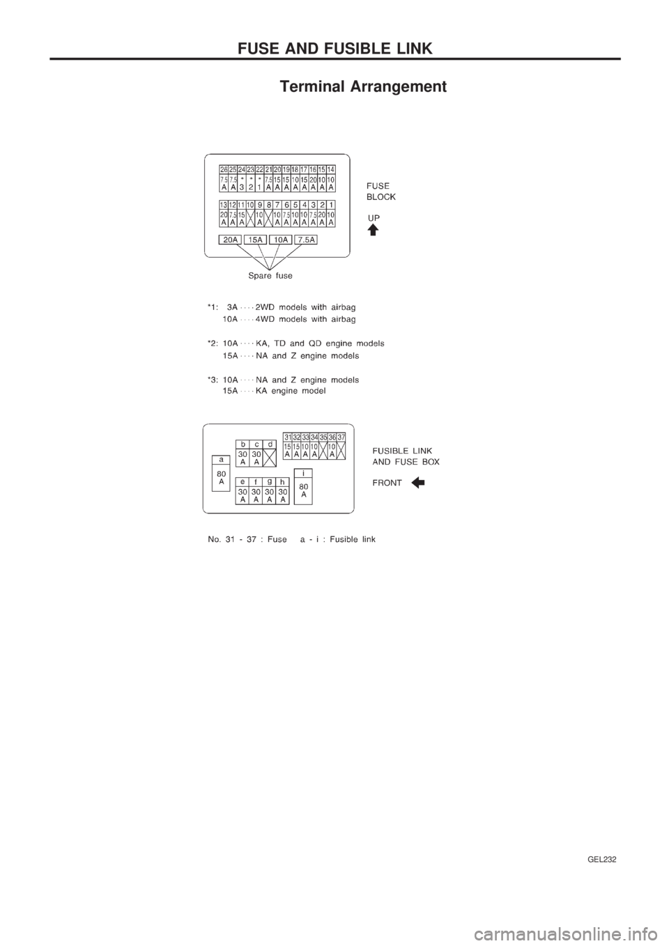
Terminal Arrangement
GEL232
FUSE AND FUSIBLE LINK
Page 815 of 1659

Description
Number Item Description
V1Power conditionlThis shows the condition when the system receives battery positive voltage (can
be operated).
V2Fusible link
lThe double line shows that this is a fusible link.
lThe open circle shows current flow in, and the shaded circle shows current flow
out.
V3Fusible link/fuse locationlThis shows the location of the fusible link or fuse in the fusible link or fuse box.
For arrangement, refer to EL section (``POWER SUPPLY ROUTING'').
V4Fuse
lThe single line shows that this is a fuse.
lThe open circle shows current flow in, and the shaded circle shows current flow
out.
V5Current ratinglThis shows the current rating of the fusible link or fuse.
V6Connectors
lThis shows that connectorE3is female and connectorM1is male.
lThe G/R wire is located in the 1A terminal of both connectors.
lTerminal number with an alphabet (1A, 5B, etc.) indicates that the connector is
SMJ connector. Refer to GI-17.
V7Optional splicelThe open circle shows that the splice is optional depending on vehicle application.
V8SplicelThe shaded circle shows that the splice is always on the vehicle.
V9Page crossinglThis arrow shows that the circuit continues to an adjacent page.
lThe A will match with the A on the preceding or next page.
V10Common connectorlThe dotted lines between terminals show that these terminals are part of the same
connector.
V11Option abbreviationlThis shows that the circuit is optional depending on vehicle application.
V12RelaylThis shows an internal representation of the relay. For details, refer to EL section
(``STANDARDIZED RELAY'').
V13ConnectorslThis shows that the connector is connected to the body or a terminal with bolt or
nut.
V14Wire color
lThis shows a code for the color of the wire.
B = Black BR = Brown
W = White OR = Orange
R = Red P = Pink
G = Green PU = Purple
L = Blue GY = Gray
Y = Yellow SB = Sky Blue
LG = Light Green CH = Dark Brown
DG = Dark Green
When the wire color is striped, the base color is given first, followed by the stripe
color as shown below:
Example: L/W = Blue with White Stripe
V15Option descriptionlThis shows a description of the option abbreviation used on the page.
V16Switch
lThis shows that continuity exists between terminals 1 and 2 when the switch is in
the A position. Continuity exists between terminals 1 and 3 when the switch is in
the B position.
V17Assembly partslConnector terminal in component shows that it is a harness incorporated assem-
bly.
V18Cell codelThis identifies each page of the wiring diagram by section, system and wiring dia-
gram page number.
HOW TO READ WIRING DIAGRAMS
GI-11