1998 NISSAN PICK-UP fuse
[x] Cancel search: fusePage 426 of 1659
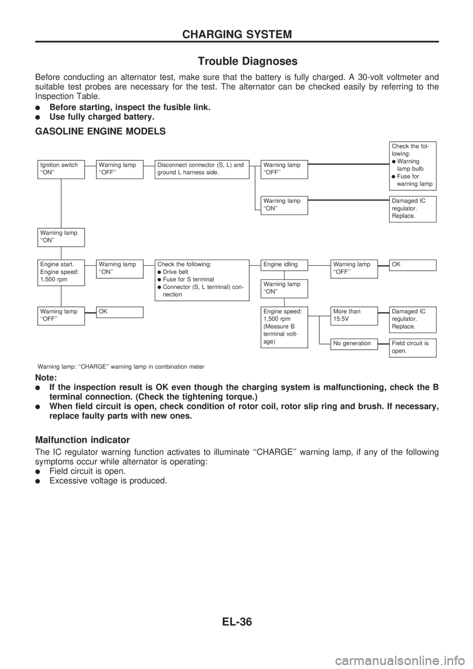
Trouble Diagnoses
Before conducting an alternator test, make sure that the battery is fully charged. A 30-volt voltmeter and
suitable test probes are necessary for the test. The alternator can be checked easily by referring to the
Inspection Table.
lBefore starting, inspect the fusible link.
lUse fully charged battery.
GASOLINE ENGINE MODELS
Check the fol-
lowing:
lWarning
lamp bulb
lFuse for
warning lamp
Ignition switch
``ON''Warning lamp
``OFF''Disconnect connector (S, L) and
ground L harness side.Warning lamp
``OFF''
Warning lamp
``ON''Damaged IC
regulator.
Replace.
Warning lamp
``ON''
Engine start.
Engine speed:
1,500 rpmWarning lamp
``ON''Check the following:lDrive beltlFuse for S terminallConnector (S, L terminal) con-
nection
Engine idlingWarning lamp
``OFF''OK
Warning lamp
``ON''
Warning lamp
``OFF''OKEngine speed:
1,500 rpm
(Measure B
terminal volt-
age)More than
15.5VDamaged IC
regulator.
Replace.
No generationField circuit is
open.
Warning lamp: ``CHARGE'' warning lamp in combination meter
Note:
lIf the inspection result is OK even though the charging system is malfunctioning, check the B
terminal connection. (Check the tightening torque.)
lWhen field circuit is open, check condition of rotor coil, rotor slip ring and brush. If necessary,
replace faulty parts with new ones.
Malfunction indicator
The IC regulator warning function activates to illuminate ``CHARGE'' warning lamp, if any of the following
symptoms occur while alternator is operating:
lField circuit is open.
lExcessive voltage is produced.
CHARGING SYSTEM
EL-36
Page 427 of 1659
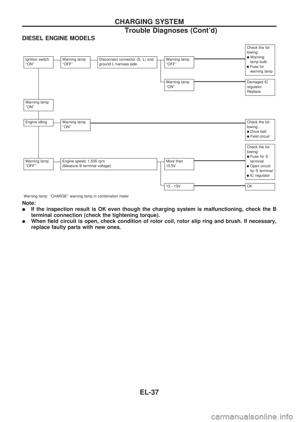
DIESEL ENGINE MODELS
Check the fol-
lowing:
lWarning
lamp bulb
lFuse for
warning lamp
Ignition switch
``ON''Warning lamp
``OFF''Disconnect connector (S, L) and
ground L harness side.Warning lamp
``OFF''
Warning lamp
``ON''Damaged IC
regulator.
Replace.
Warning lamp
``ON''
Engine idlingWarning lamp
``ON''Check the fol-
lowing:
lDrive beltlField circuit
Check the fol-
lowing:
lFuse for S
terminal
lOpen circuit
for S terminal
lIC regulator
Warning lamp
``OFF''Engine speed: 1,500 rpm
(Measure B terminal voltage)More than
15.5V
13 - 15VOK
Warning lamp: ``CHARGE'' warning lamp in combination meter
Note:
lIf the inspection result is OK even though the charging system is malfunctioning, check the B
terminal connection (check the tightening torque).
lWhen field circuit is open, check condition of rotor coil, rotor slip ring and brush. If necessary,
replace faulty parts with new ones.
CHARGING SYSTEM
Trouble Diagnoses (Cont'd)
EL-37
Page 438 of 1659
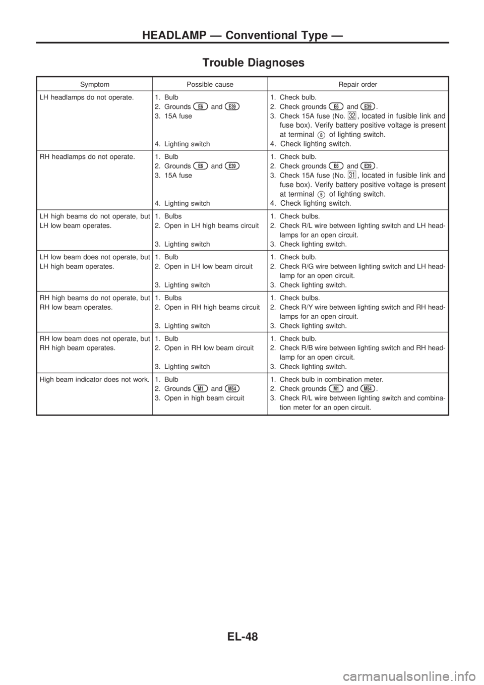
Trouble Diagnoses
Symptom Possible cause Repair order
LH headlamps do not operate. 1. Bulb
2. Grounds
E6andE39
3. 15A fuse
4. Lighting switch1. Check bulb.
2. Check grounds
E6andE39.
3. Check 15A fuse (No.
32, located in fusible link and
fuse box). Verify battery positive voltage is present
at terminal
V8of lighting switch.
4. Check lighting switch.
RH headlamps do not operate. 1. Bulb
2. Grounds
E6andE39
3. 15A fuse
4. Lighting switch1. Check bulb.
2. Check grounds
E6andE39.
3. Check 15A fuse (No.
31, located in fusible link and
fuse box). Verify battery positive voltage is present
at terminal
V5of lighting switch.
4. Check lighting switch.
LH high beams do not operate, but
LH low beam operates.1. Bulbs
2. Open in LH high beams circuit
3. Lighting switch1. Check bulbs.
2. Check R/L wire between lighting switch and LH head-
lamps for an open circuit.
3. Check lighting switch.
LH low beam does not operate, but
LH high beam operates.1. Bulb
2. Open in LH low beam circuit
3. Lighting switch1. Check bulb.
2. Check R/G wire between lighting switch and LH head-
lamp for an open circuit.
3. Check lighting switch.
RH high beams do not operate, but
RH low beam operates.1. Bulbs
2. Open in RH high beams circuit
3. Lighting switch1. Check bulbs.
2. Check R/Y wire between lighting switch and RH head-
lamps for an open circuit.
3. Check lighting switch.
RH low beam does not operate, but
RH high beam operates.1. Bulb
2. Open in RH low beam circuit
3. Lighting switch1. Check bulb.
2. Check R/B wire between lighting switch and RH head-
lamp for an open circuit.
3. Check lighting switch.
High beam indicator does not work. 1. Bulb
2. Grounds
M1andM54
3. Open in high beam circuit1. Check bulb in combination meter.
2. Check grounds
M1andM54.
3. Check R/L wire between lighting switch and combina-
tion meter for an open circuit.
HEADLAMP Ð Conventional Type Ð
EL-48
Page 470 of 1659
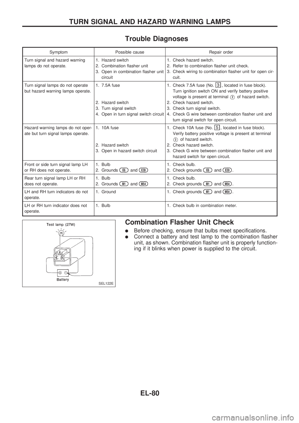
Trouble Diagnoses
Symptom Possible cause Repair order
Turn signal and hazard warning
lamps do not operate.1. Hazard switch
2. Combination flasher unit
3. Open in combination flasher unit
circuit1. Check hazard switch.
2. Refer to combination flasher unit check.
3. Check wiring to combination flasher unit for open cir-
cuit.
Turn signal lamps do not operate
but hazard warning lamps operate.1. 7.5A fuse
2. Hazard switch
3. Turn signal switch
4. Open in turn signal switch circuit1. Check 7.5A fuse (No.
, located in fuse block).
Turn ignition switch ON and verify battery positive
voltage is present at terminal
V2of hazard switch.
2. Check hazard switch.
3. Check turn signal switch.
4. Check G wire between combination flasher unit and
turn signal switch for open circuit.
Hazard warning lamps do not oper-
ate but turn signal lamps operate.1. 10A fuse
2. Hazard switch
3. Open in hazard switch circuit1. Check 10A fuse (No.
, located in fuse block).
Verify battery positive voltage is present at terminal
V3of hazard switch.
2. Check hazard switch.
3. Check G wire between combination flasher unit and
hazard switch for open circuit.
Front or side turn signal lamp LH
or RH does not operate.1. Bulb
2. Grounds
E6andE39
1. Check bulb.
2. Check grounds
E6andE39.
Rear turn signal lamp LH or RH
does not operate.1. Bulb
2. Grounds
M1andM54
1. Check bulb.
2. Check grounds
M1andM54.
LH and RH turn indicators do not
operate.1. Ground 1. Check grounds
M1andM54.
LH or RH turn indicator does not
operate.1. Bulb 1. Check bulb in combination meter.
Combination Flasher Unit Check
lBefore checking, ensure that bulbs meet specifications.
lConnect a battery and test lamp to the combination flasher
unit, as shown. Combination flasher unit is properly function-
ing if it blinks when power is supplied to the circuit.
SEL122E
TURN SIGNAL AND HAZARD WARNING LAMPS
EL-80
Page 490 of 1659
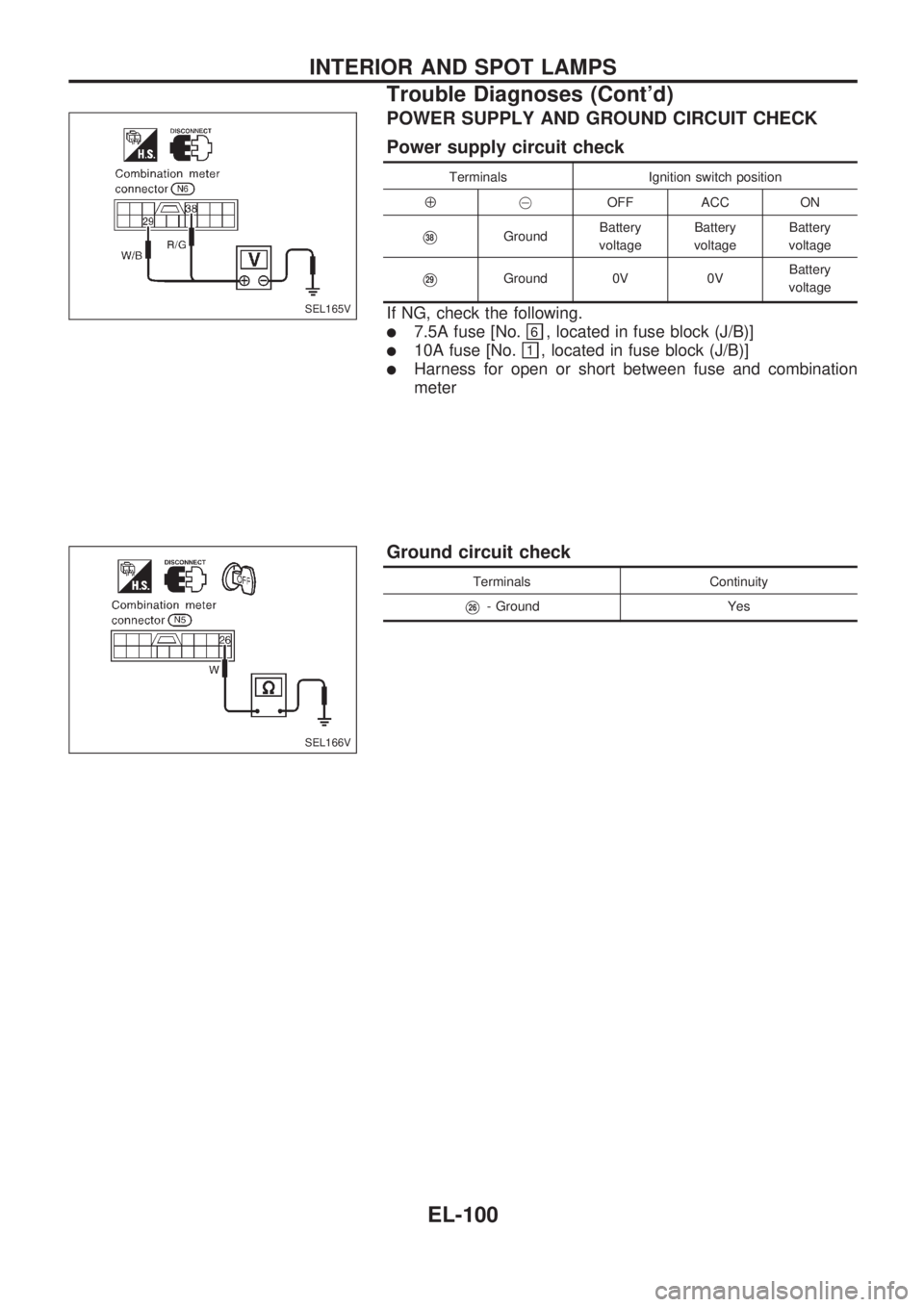
POWER SUPPLY AND GROUND CIRCUIT CHECK
Power supply circuit check
Terminals Ignition switch position
Å@OFF ACC ON
V38GroundBattery
voltageBattery
voltageBattery
voltage
V29Ground 0V 0VBattery
voltage
If NG, check the following.
l7.5A fuse [No., located in fuse block (J/B)]
l10A fuse [No., located in fuse block (J/B)]
lHarness for open or short between fuse and combination
meter
Ground circuit check
Terminals Continuity
V26- Ground Yes
SEL165V
SEL166V
INTERIOR AND SPOT LAMPS
Trouble Diagnoses (Cont'd)
EL-100
Page 510 of 1659
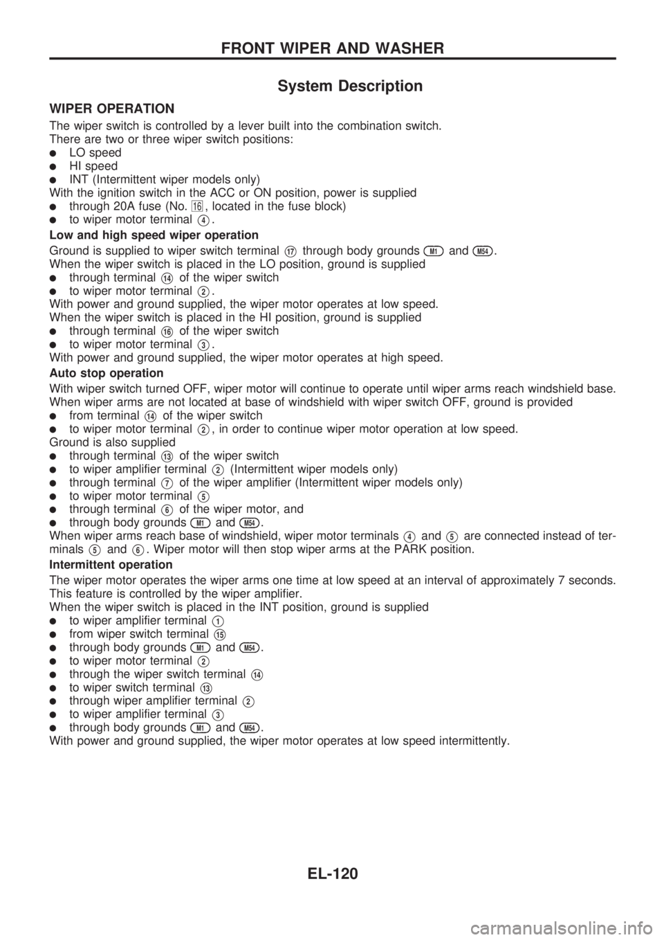
System Description
WIPER OPERATION
The wiper switch is controlled by a lever built into the combination switch.
There are two or three wiper switch positions:
lLO speed
lHI speed
lINT (Intermittent wiper models only)
With the ignition switch in the ACC or ON position, power is supplied
lthrough 20A fuse (No.16, located in the fuse block)
lto wiper motor terminalV4.
Low and high speed wiper operation
Ground is supplied to wiper switch terminal
V17through body groundsM1andM54.
When the wiper switch is placed in the LO position, ground is supplied
lthrough terminalV14of the wiper switch
lto wiper motor terminalV2.
With power and ground supplied, the wiper motor operates at low speed.
When the wiper switch is placed in the HI position, ground is supplied
lthrough terminalV16of the wiper switch
lto wiper motor terminalV3.
With power and ground supplied, the wiper motor operates at high speed.
Auto stop operation
With wiper switch turned OFF, wiper motor will continue to operate until wiper arms reach windshield base.
When wiper arms are not located at base of windshield with wiper switch OFF, ground is provided
lfrom terminalV14of the wiper switch
lto wiper motor terminalV2, in order to continue wiper motor operation at low speed.
Ground is also supplied
lthrough terminalV13of the wiper switch
lto wiper amplifier terminalV2(Intermittent wiper models only)
lthrough terminalV7of the wiper amplifier (Intermittent wiper models only)
lto wiper motor terminalV5
lthrough terminalV6of the wiper motor, and
lthrough body groundsM1andM54.
When wiper arms reach base of windshield, wiper motor terminals
V4andV5are connected instead of ter-
minals
V5andV6. Wiper motor will then stop wiper arms at the PARK position.
Intermittent operation
The wiper motor operates the wiper arms one time at low speed at an interval of approximately 7 seconds.
This feature is controlled by the wiper amplifier.
When the wiper switch is placed in the INT position, ground is supplied
lto wiper amplifier terminalV1
lfrom wiper switch terminalV15
lthrough body groundsM1andM54.
lto wiper motor terminalV2
lthrough the wiper switch terminalV14
lto wiper switch terminalV13
lthrough wiper amplifier terminalV2
lto wiper amplifier terminalV3
lthrough body groundsM1andM54.
With power and ground supplied, the wiper motor operates at low speed intermittently.
FRONT WIPER AND WASHER
EL-120
Page 511 of 1659
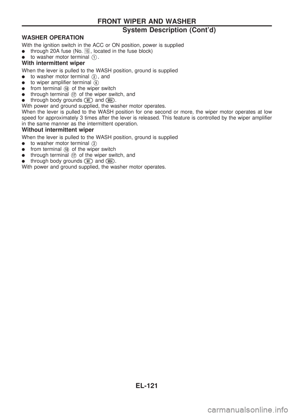
WASHER OPERATION
With the ignition switch in the ACC or ON position, power is supplied
lthrough 20A fuse (No.16, located in the fuse block)
lto washer motor terminalV1.
With intermittent wiper
When the lever is pulled to the WASH position, ground is supplied
lto washer motor terminalV2, and
lto wiper amplifier terminalV6
lfrom terminalV18of the wiper switch
lthrough terminalV17of the wiper switch, and
lthrough body groundsM1andM54.
With power and ground supplied, the washer motor operates.
When the lever is pulled to the WASH position for one second or more, the wiper motor operates at low
speed for approximately 3 times after the lever is released. This feature is controlled by the wiper amplifier
in the same manner as the intermittent operation.
Without intermittent wiper
When the lever is pulled to the WASH position, ground is supplied
lto washer motor terminalV2
lfrom terminalV18of the wiper switch
lthrough terminalV17of the wiper switch, and
lthrough body groundsM1andM54.
With power and ground supplied, the washer motor operates.
FRONT WIPER AND WASHER
System Description (Cont'd)
EL-121
Page 516 of 1659
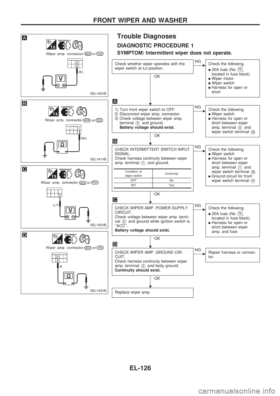
Trouble Diagnoses
DIAGNOSTIC PROCEDURE 1
SYMPTOM: Intermittent wiper does not operate.
Check whether wiper operates with the
wiper switch at Lo position.
OK
cNG
Check the following.
l20A fuse (No.16,
located in fuse block)
lWiper motorlWiper switchlHarness for open or
short
1) Turn front wiper switch to OFF.
2) Disconnect wiper amp. connector.
3) Check voltage between wiper amp.
terminal
V2and ground.
Battery voltage should exist.
OK
cNG
Check the following.
lWiper switchlHarness for open or
short between wiper
amp. terminal
V2and
wiper switch terminal
V13
CHECK INTERMITTENT SWITCH INPUT
SIGNAL.
Check harness continuity between wiper
amp. terminal
V1and ground.
OK
cNG
Check the following.
lWiper switchlHarness for open or
short between wiper
amp. terminal
V1and
wiper switch terminal
V15lGround circuit for front
wiper switch terminal
V17
CHECK WIPER AMP. POWER SUPPLY
CIRCUIT.
Check voltage between wiper amp. termi-
nal
V5and ground while ignition switch is
``ACC''.
Battery voltage should exist.
OK
cNG
Check the following.
l20A fuse (No.16,
located in fuse block)
lHarness for open or
short between wiper
amp. and fuse
CHECK WIPER AMP. GROUND CIR-
CUIT.
Check harness continuity between wiper
amp. terminal
V3and body ground.
Continuity should exist.
OK
cNG
Repair harness or connec-
tor.
Replace wiper amp.
Condition of
wiper switchContinuity
OFF No
INT Yes
SEL140VB
SEL141VB
SEL142VB
SEL143VB
.
.
.
.
.
FRONT WIPER AND WASHER
EL-126