1998 NISSAN PICK-UP fuse
[x] Cancel search: fusePage 816 of 1659

Number Item Description
V19Current flow arrow
lArrow indicates electric current flow, especially where the direction of standard
flow (vertically downward or horizontally from left to right) is difficult to follow.
lA double arrow ``bÐ
c'' shows that current can flow in either direction depending
on circuit operation.
V20System branchlThis shows that the system branches to another system identified by cell code
(section and system).
V21Page crossing
lThis arrow shows that the circuit continues to another page identified by cell code.
lThe C will match with the C on another page within the system other than the next
or preceding pages.
V22Shielded linelThe line enclosed by broken line circle shows shield wire.
V23Component box in wave
linelThis shows that another part of the component is also shown on another page
(indicated by wave line) within the system.
V24Component namelThis shows the name of a component.
V25Connector number
lThis shows the connector number.
lThe letter shows which harness the connector is located in.
Example:M: main harness. For detail and to locate the connector, refer to EL sec-
tion (``Main Harness'', ``HARNESS LAYOUT''). A coordinate grid is included for
complex harnesses to aid in locating connectors.
V26Ground (GND)lThe line spliced and grounded under wire color shows that ground line is spliced
at the grounded connector.
V27Ground (GND)lThis shows the ground connection.
V28Connector viewslThis area shows the connector faces of the components in the wiring diagram on
the page.
V29Common componentlConnectors enclosed in broken line show that these connectors belong to the
same component.
V30Connector colorlThis shows a code for the color of the connector. For code meaning, refer to wire
color codes, Number
V14of this chart.
V31Fusible link and fuse box
lThis shows the arrangement of fusible link(s) and fuse(s), used for connector
views of ``POWER SUPPLY ROUTING'' in EL section.
The open square shows current flow in, and the shaded square shows current
flow out.
V32Reference arealThis shows that more information on the Super Multiple Junction (SMJ) and Joint
Connectors (J/C) exists on the foldout page. Refer to GI-17 for details.
HOW TO READ WIRING DIAGRAMS
Description (Cont'd)
GI-12
Page 829 of 1659
Circuit Inspection
INTRODUCTION
In general, testing electrical circuits is an easy task if it is approached in a logical and organized method.
Before beginning it is important to have all available information on the system to be tested. Also, get a
thorough understanding of system operation. Then you will be able to use the appropriate equipment and
follow the correct test procedure.
You may have to simulate vehicle vibrations while testing electrical components.Gently shakethe wiring
harness or electrical component to do this.
OPEN A circuit is open when there is no continuity through a section of the circuit.
SHORT There are two types of shorts.
lSHORT CIRCUITWhen a circuit contacts another circuit and causes the
normal resistance to change.
lSHORT TO GROUNDWhen a circuit contacts a ground source and grounds the
circuit.
TESTING FOR ``OPENS'' IN THE CIRCUIT
Before you begin to diagnose and test the system, you should rough sketch a schematic of the system. This
will help you to logically walk through the diagnosis process. Drawing the sketch will also reinforce your
working knowledge of the system.
Continuity check method
The continuity check is used to find an open in the circuit. The Digital Multimeter (DMM) set on the resis-
tance function will indicate an open circuit as over limit (no beep tone or no ohms symbol). Make sure to
always start with the DMM at the highest resistance level.
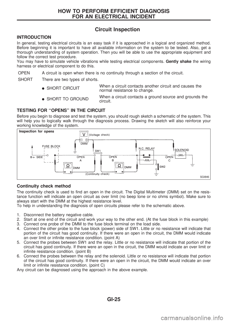
To help in understanding the diagnosis of open circuits please refer to the schematic above.
1. Disconnect the battery negative cable.
2. Start at one end of the circuit and work your way to the other end. (At the fuse block in this example)
3. Connect one probe of the DMM to the fuse block terminal on the load side.
4. Connect the other probe to the fuse block (power) side of SW1. Little or no resistance will indicate that
portion of the circuit has good continuity. If there were an open in the circuit, the DMM would indicate
an over limit or infinite resistance condition. (point A)
5. Connect the probes between SW1 and the relay. Little or no resistance will indicate that portion of the
circuit has good continuity. If there were an open in the circuit, the DMM would indicate an over limit or
infinite resistance condition. (point B)
6. Connect the probes between the relay and the solenoid. Little or no resistance will indicate that portion
of the circuit has good continuity. If there were an open in the circuit, the DMM would indicate an over
limit or infinite resistance condition. (point C)
Any circuit can be diagnosed using the approach in the above example.
SGI846
HOW TO PERFORM EFFICIENT DIAGNOSIS
FOR AN ELECTRICAL INCIDENT
GI-25
Page 830 of 1659
Voltage check method
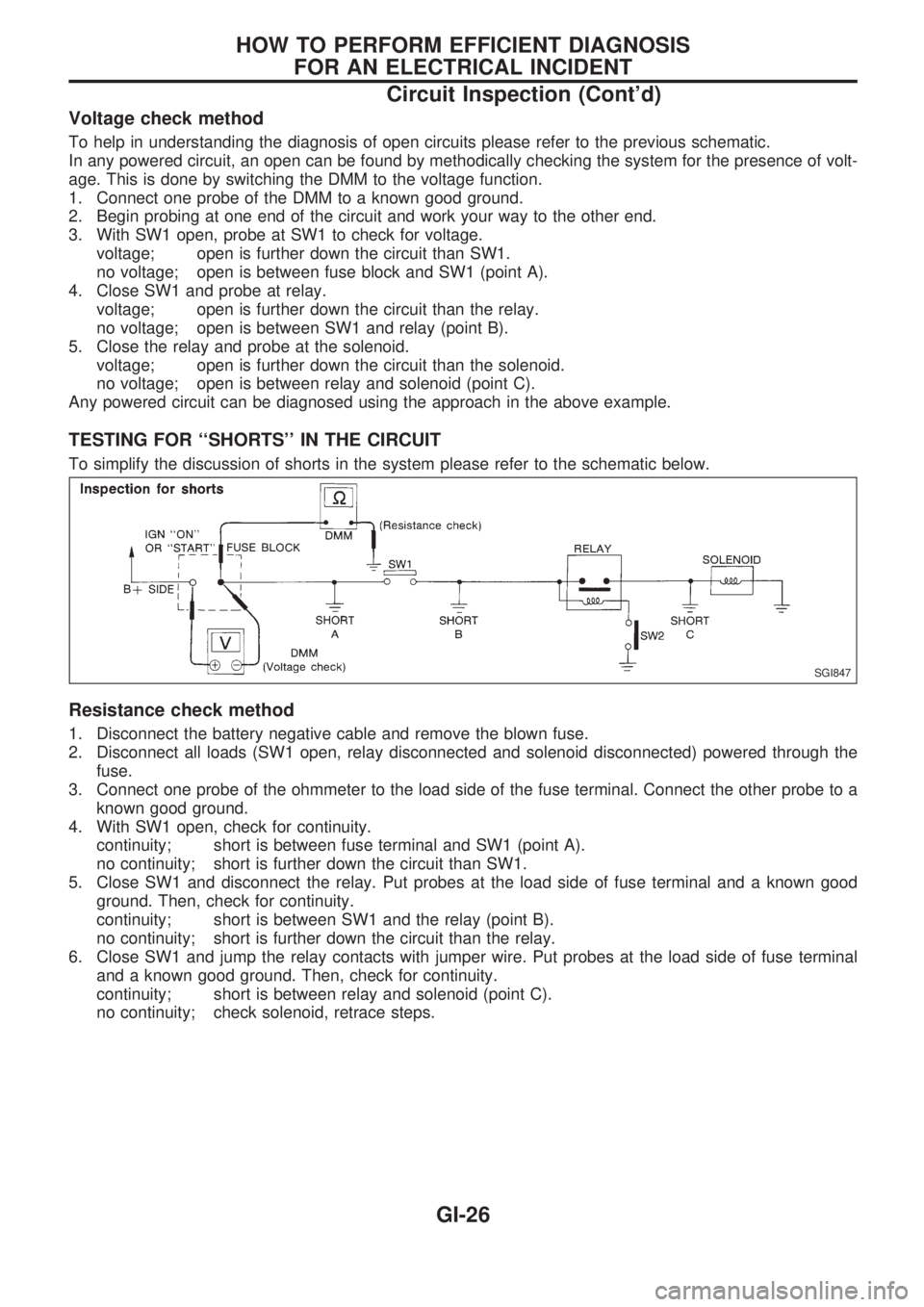
To help in understanding the diagnosis of open circuits please refer to the previous schematic.
In any powered circuit, an open can be found by methodically checking the system for the presence of volt-
age. This is done by switching the DMM to the voltage function.
1. Connect one probe of the DMM to a known good ground.
2. Begin probing at one end of the circuit and work your way to the other end.
3. With SW1 open, probe at SW1 to check for voltage.
voltage; open is further down the circuit than SW1.
no voltage; open is between fuse block and SW1 (point A).
4. Close SW1 and probe at relay.
voltage; open is further down the circuit than the relay.
no voltage; open is between SW1 and relay (point B).
5. Close the relay and probe at the solenoid.
voltage; open is further down the circuit than the solenoid.
no voltage; open is between relay and solenoid (point C).
Any powered circuit can be diagnosed using the approach in the above example.
TESTING FOR ``SHORTS'' IN THE CIRCUIT
To simplify the discussion of shorts in the system please refer to the schematic below.
Resistance check method
1. Disconnect the battery negative cable and remove the blown fuse.
2. Disconnect all loads (SW1 open, relay disconnected and solenoid disconnected) powered through the
fuse.
3. Connect one probe of the ohmmeter to the load side of the fuse terminal. Connect the other probe to a
known good ground.
4. With SW1 open, check for continuity.
continuity; short is between fuse terminal and SW1 (point A).
no continuity; short is further down the circuit than SW1.
5. Close SW1 and disconnect the relay. Put probes at the load side of fuse terminal and a known good
ground. Then, check for continuity.
continuity; short is between SW1 and the relay (point B).
no continuity; short is further down the circuit than the relay.
6. Close SW1 and jump the relay contacts with jumper wire. Put probes at the load side of fuse terminal
and a known good ground. Then, check for continuity.
continuity; short is between relay and solenoid (point C).
no continuity; check solenoid, retrace steps.
SGI847
HOW TO PERFORM EFFICIENT DIAGNOSIS
FOR AN ELECTRICAL INCIDENT
Circuit Inspection (Cont'd)
GI-26
Page 831 of 1659
Voltage check method
1. Remove the blown fuse and disconnect all loads (i.e. SW1 open, relay disconnected and solenoid dis-
connected) powered through the fuse.
2. Turn the ignition key to the ON or START position. Verify battery voltage at the B
+side of the fuse ter-
minal (one lead on the B
+terminal side of the fuse block and one lead on a known good ground).
3. With SW1 open and the DMM leads across both fuse terminals, check for voltage.
voltage; short is between fuse block and SW1 (point A).
no voltage; short is further down the circuit than SW1.
4. With SW1 closed, relay and solenoid disconnected and the DMM leads across both fuse terminals, check
for voltage.
voltage; short is between SW1 and the relay (point B).
no voltage; short is further down the circuit than the relay.
5. With SW1 closed, relay contacts jumped with fused jumper wire check for voltage.
voltage; short is down the circuit of the relay or between the relay and the disconnected solenoid
(point C).
no voltage; retrace steps and check power to fuse block.
GROUND INSPECTION
Ground connections are very important to the proper operation of electrical and electronic circuits. Ground
connections are often exposed to moisture, dirt and other corrosive elements. The corrosion (rust) can
become an unwanted resistance. This unwanted resistance can change the way a circuit works.
Electronically controlled circuits are very sensitive to proper grounding. A loose or corroded ground can
drastically affect an electronically controlled circuit. A poor or corroded ground can easily affect the circuit.
Even when the ground connection looks clean, there can be a thin film of rust on the surface.
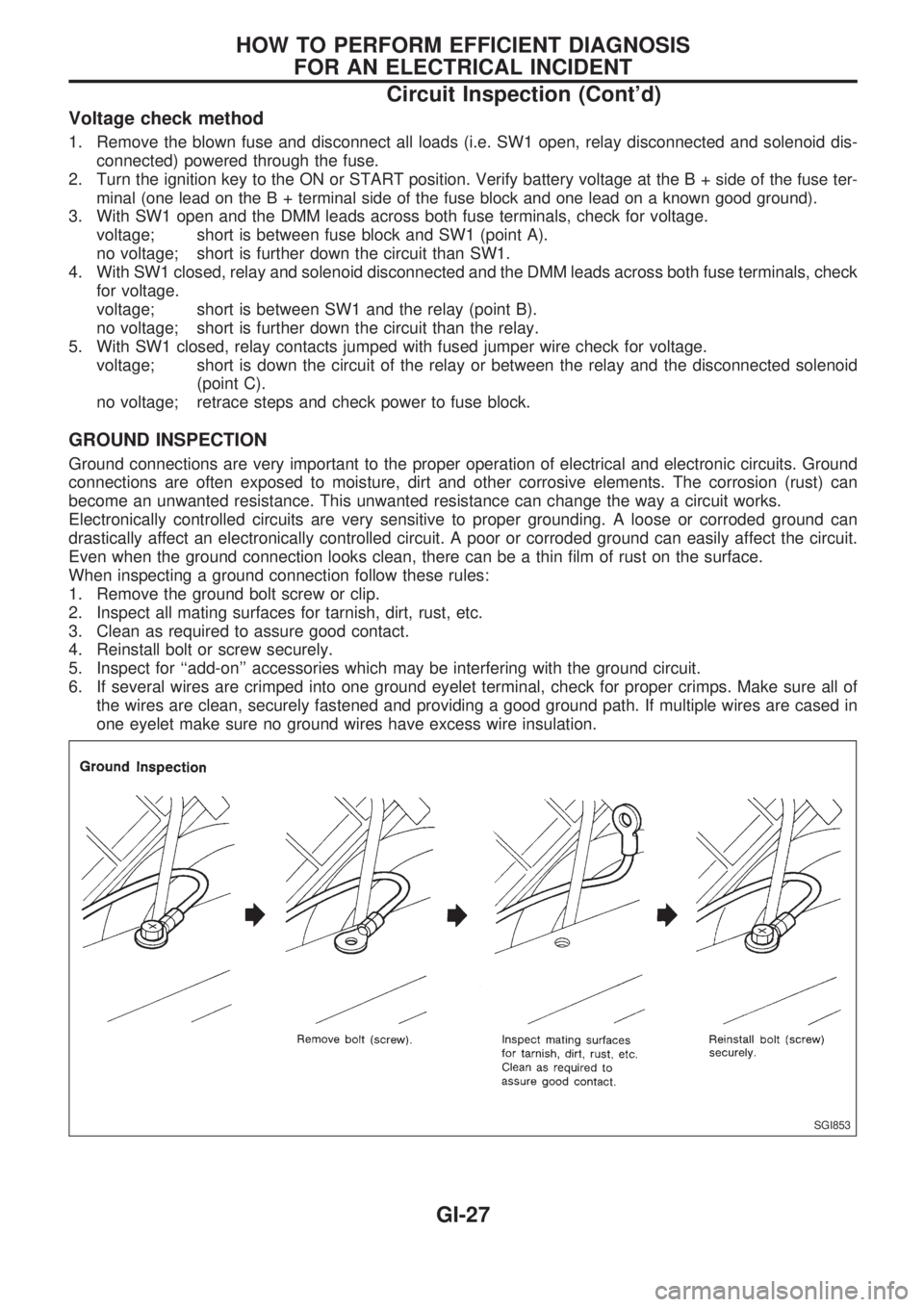
When inspecting a ground connection follow these rules:
1. Remove the ground bolt screw or clip.
2. Inspect all mating surfaces for tarnish, dirt, rust, etc.
3. Clean as required to assure good contact.
4. Reinstall bolt or screw securely.
5. Inspect for ``add-on'' accessories which may be interfering with the ground circuit.
6. If several wires are crimped into one ground eyelet terminal, check for proper crimps. Make sure all of
the wires are clean, securely fastened and providing a good ground path. If multiple wires are cased in
one eyelet make sure no ground wires have excess wire insulation.
SGI853
HOW TO PERFORM EFFICIENT DIAGNOSIS
FOR AN ELECTRICAL INCIDENT
Circuit Inspection (Cont'd)
GI-27
Page 837 of 1659

KEY TO SYMBOLS SIGNIFYING MEASUREMENTS OR PROCEDURES
Symbol Symbol explanation Symbol Symbol explanation
Check after disconnecting the connector
to be measured.Procedure with CONSULT
Check after connecting the connector to
be measured.Procedure without CONSULT
Insert key into ignition switch.A/C switch is ``OFF''.
Remove key from ignition switch.A/C switch is ``ON''.
Turn ignition switch to ``OFF'' position.Fan switch is ``ON''. (At any position
except for ``OFF'' position)
Turn ignition switch to ``ON'' position.Fan switch is ``OFF''.
Turn ignition switch to ``START'' position.Apply positive voltage from battery with
fuse directly to components.
Turn ignition switch from ``OFF'' to ``ACC''
position.Drive vehicle.
Turn ignition switch from ``ACC'' to ``OFF''
position.Disconnect battery negative cable.
Turn ignition switch from ``OFF'' to ``ON''
position.Depress brake pedal.
Turn ignition switch from ``ON'' to ``OFF''
position.Release brake pedal.
Do not start engine, or check with engine
stopped.Depress accelerator pedal.
Start engine, or check with engine run-
ning.Release accelerator pedal.
Apply parking brake.
Pin terminal check for SMJ type ECM
and TCM control unit connectors.
For details regarding the terminal
arrangement, refer to the foldout page.Release parking brake.
Check after engine is warmed up suffi-
ciently.
Voltage should be measured with a volt-
meter.
Circuit resistance should be measured
with an ohmmeter.
Current should be measured with an
ammeter.
HOW TO FOLLOW FLOW CHART IN TROUBLE DIAGNOSES
How to Follow This Flow Chart (Cont'd)
GI-33
Page 866 of 1659

EVAP vapor lines inspection ....................... MA-22
Electrical diagnoses ...................................... GI-21
Engine compartment .................................... BT-44
Engine control module (ECM) ....................... EC-5
Engine coolant temperature sensor
(ECTS) (KA24 engine) ............................. EC-95
Engine coolant temperature sensor
(ECTS) (TD25 engine) ........................... EC-209
Engine oil filter replacement
(KA24 engine).......................................... MA-20
Engine oil filter replacement
(TD25 engine).......................................... MA-24
Engine oil precautions .................................... GI-4
Engine oil replacement
(KA24 engine).......................................... MA-19
Engine oil replacement
(TD25 engine).......................................... MA-24
Engine outer component parts
(KA24 engine)............................................ EM-9
Engine outer component parts
(TD25 engine).......................................... EM-49
Engine removal (KA24 engine) ................... EM-36
Engine removal (TD25 engine) ................... EM-69
Engine room - See Engine
compartment............................................. BT-44
Engine speed sensor ................................. EC-219
Evaporative emission (EVAP) system ......... EC-19
Exhaust system inspection.......................... MA-32
Exhaust system .............................................. FE-5
Exterior ......................................................... BT-24
F
F/PUMP - Wiring diagram...........................EC-153
FCUT - Wiring diagram ............................. EC-225
FICD - Wiring diagram (KA24 engine) ...... EC-168
FICD - Wiring diagram (TD25 engine) ...... EC-230
Fan switch.................................................... HA-43
Fast idle cam (FIC) inspection and
adjustment................................................ EC-24
Final drive disassembly (C200) ................... PD-34
Final drive disassembly (H233B)................. PD-56
Final drive pre-inspection (C200) ................ PD-34
Final drive pre-inspection (H233B) .............. PD-56
Final drive removal and installation ............. PD-15
Floor trim ...................................................... BT-15
Flow charts.................................................... GI-31
Fluids ........................................................... MA-12
Flywheel (clutch) .......................................... CL-12
Flywheel runout (KA24 engine)................... EM-45
Flywheel runout (TD25 engine)................... EM-80
Fog lamp, rear .............................................. EL-72
Fork rod (M/T) (FS5R30A) .......................... MT-38
Fork rod (M/T) (FS5W71C) ......................... MT-17
Front axle ..................................................... FA-12
Front bumper.................................................. BT-5
Front case (Transfer) ..................................... TF-8
Front combination lamp removal and
installation................................................... BT-5Front disc brake ........................................... BR-21
Front door..................................................... BT-10
Front drive shaft (Transfer) ............................ TF-9
Front final drive disassembly (4WD) ........... PD-17
Front final drive pre-inspection (4WD) ........ PD-17
Front final drive removal and installa-
tion (4WD) ................................................ PD-14
Front seat belt................................................ RS-3
Front seat ..................................................... BT-30
Front suspension.......................................... FA-26
Front washer .............................................. EL-120
Front wiper ................................................. EL-120
Fuel check valve .......................................... EC-20
Fuel cut control (at no load & high
engine speed) (KA24 engine) .................. EC-18
Fuel cut control (at no load & high
engine speed) ........................................ EC-225
Fuel filter replacement (KA24 engine) ........ MA-18
Fuel filter replacement (TD25 engine) ........ MA-27
Fuel injector ............................................... EC-144
Fuel line inspection (KA24 engine) ............. MA-18
Fuel line inspection (TD25 engine) ............. MA-28
Fuel precautions ............................................. GI-5
Fuel pressure check .................................... EC-22
Fuel pressure release .................................. EC-22
Fuel pump .................................................. EC-151
Fuel pump relay ......................................... EC-156
Fuel system .................................................... FE-3
Fuel tank vacuum relief valve...................... EC-20
Fuse block.................................................. Foldout
Fuse.............................................................. EL-13
Fusible link ................................................... EL-13G
GLOW - Wiring diagram .............................EC-197
Garage jack and safety stand....................... GI-49
Gear components (M/T) (FS5R30A) ........... MT-36
Gear components (M/T) (FS5W71C) .......... MT-15
Glass ............................................................ BT-10
Glow plug ................................................... EC-208
Glow relay .................................................. EC-208
Grease ......................................................... MA-12
Ground clearance ......................................... GI-44
Ground distribution ....................................... EL-14
H
H/AIM - Wiring diagram .................................EL-64
H/LAMP - Wiring diagram ............................ EL-44
H02S - Wiring diagram .............................. EC-124
HFC134a (R134a) system precaution ........... HA-2
HFC134a (R134a) system service
procedure ................................................. HA-48
HFC134a (R134a) system service
tools............................................................ HA-8
HFC134a system service equipment
precaution ................................................ HA-10
ALPHABETICAL INDEX
IDX-4
Page 874 of 1659
CAUTION:
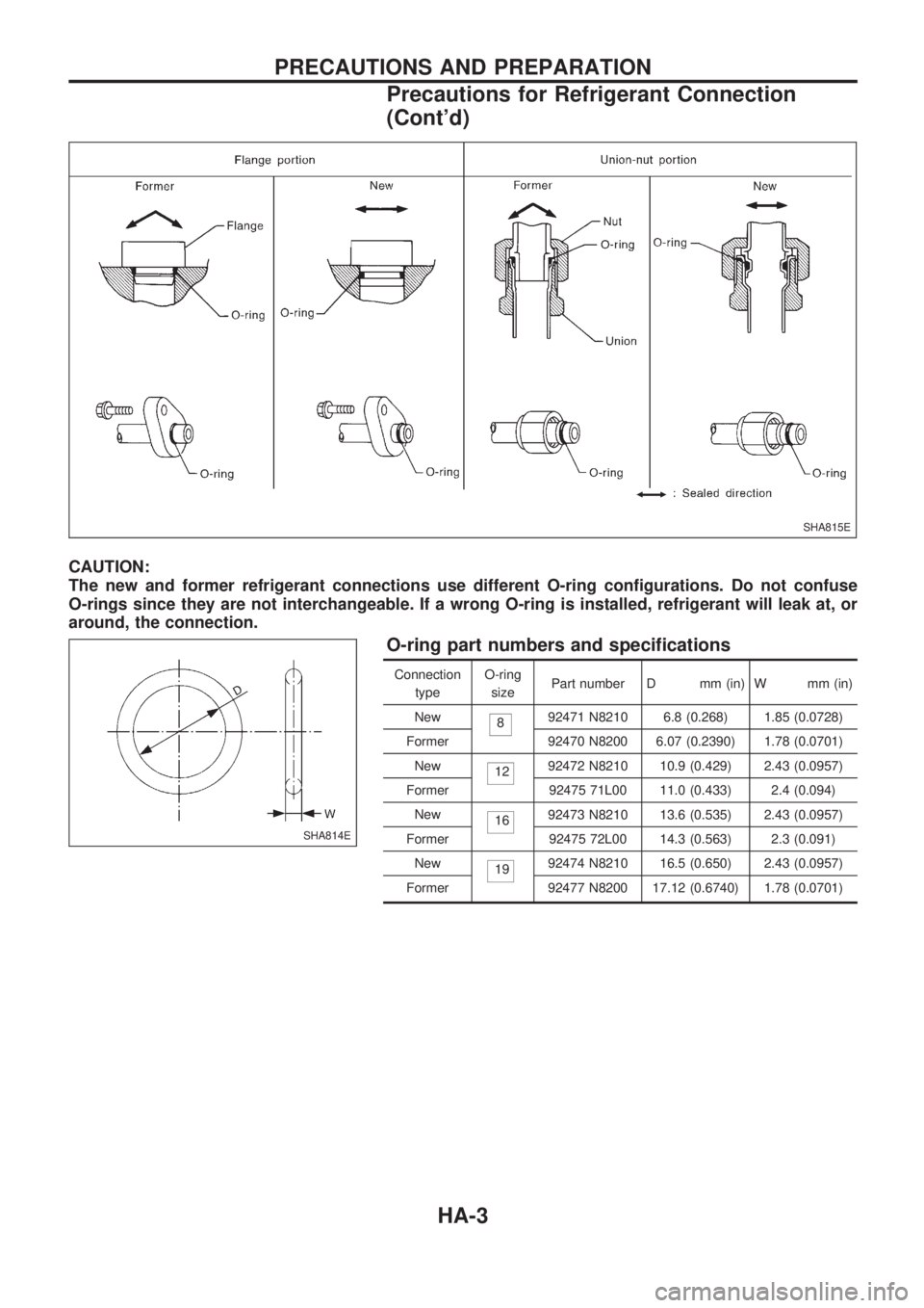
The new and former refrigerant connections use different O-ring configurations. Do not confuse
O-rings since they are not interchangeable. If a wrong O-ring is installed, refrigerant will leak at, or
around, the connection.
O-ring part numbers and specifications
Connection
typeO-ring
sizePart number D mm (in) W mm (in)
New
892471 N8210 6.8 (0.268) 1.85 (0.0728)
Former 92470 N8200 6.07 (0.2390) 1.78 (0.0701)
New
1292472 N8210 10.9 (0.429) 2.43 (0.0957)
Former 92475 71L00 11.0 (0.433) 2.4 (0.094)
New
1692473 N8210 13.6 (0.535) 2.43 (0.0957)
Former 92475 72L00 14.3 (0.563) 2.3 (0.091)
New
1992474 N8210 16.5 (0.650) 2.43 (0.0957)
Former 92477 N8200 17.12 (0.6740) 1.78 (0.0701)
SHA815E
SHA814E
PRECAUTIONS AND PREPARATION
Precautions for Refrigerant Connection
(Cont'd)
HA-3
Page 891 of 1659
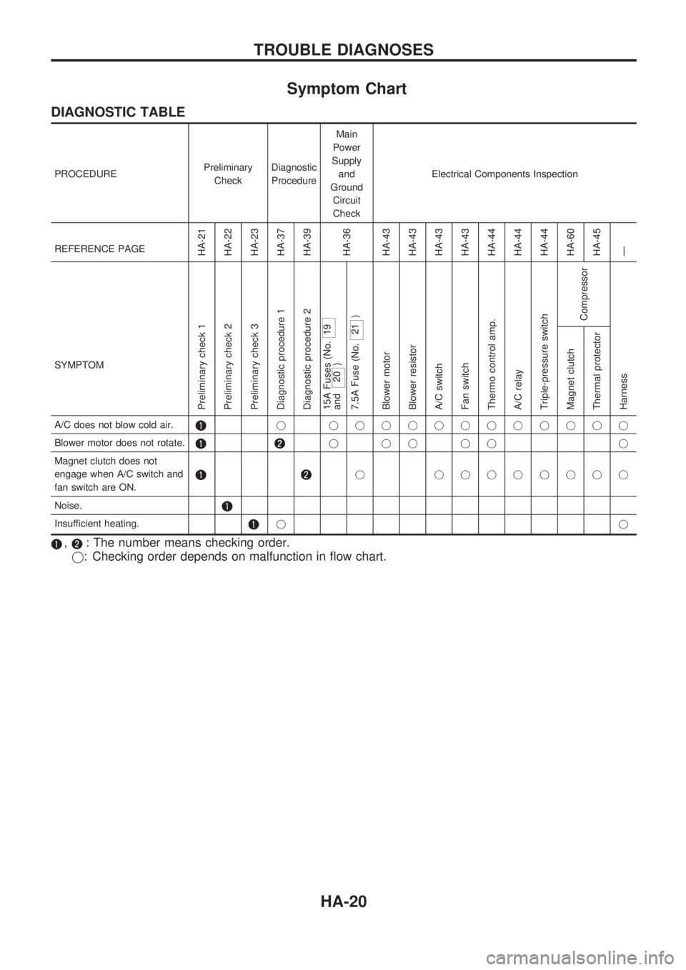
Symptom Chart
DIAGNOSTIC TABLE
PROCEDUREPreliminary
CheckDiagnostic
ProcedureMain
Power
Supply
and
Ground
Circuit
CheckElectrical Components Inspection
REFERENCE PAGE
HA-21
HA-22
HA-23
HA-37
HA-39
HA-36
HA-43
HA-43
HA-43
HA-43
HA-44
HA-44
HA-44
HA-60
HA-45
Ð
SYMPTOM
Preliminary check 1
Preliminary check 2
Preliminary check 3
Diagnostic procedure 1
Diagnostic procedure 2
15A Fuses (No.
19
and
20 )
7.5A Fuse (No.
21 )
Blower motor
Blower resistor
A/C switch
Fan switch
Thermo control amp.
A/C relay
Triple-pressure switch
Compressor
Harness Magnet clutch
Thermal protector
A/C does not blow cold air.j jjjjjjjjjjjj
Blower motor does not rotate.
jjjjj j
Magnet clutch does not
engage when A/C switch and
fan switch are ON.
j jjjjjjjj
Noise.
Insufficient heating.jj
,: The number means checking order.
j: Checking order depends on malfunction in flow chart.
TROUBLE DIAGNOSES
HA-20