1998 NISSAN PICK-UP ECO mode
[x] Cancel search: ECO modePage 210 of 1659
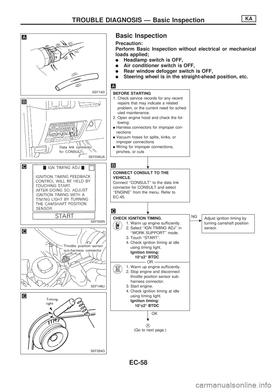
Basic Inspection
Precaution:
Perform Basic Inspection without electrical or mechanical
loads applied;
lHeadlamp switch is OFF,
lAir conditioner switch is OFF,
lRear window defogger switch is OFF,
lSteering wheel is in the straight-ahead position, etc.
BEFORE STARTING
1. Check service records for any recent
repairs that may indicate a related
problem, or the current need for sched-
uled maintenance.
2. Open engine hood and check the fol-
lowing:
lHarness connectors for improper con-
nections
lVacuum hoses for splits, kinks, or
improper connections
lWiring for improper connections,
pinches, or cuts
CONNECT CONSULT TO THE
VEHICLE.
Connect ``CONSULT'' to the data link
connector for CONSULT and select
``ENGINE'' from the menu. Refer to
EC-45.
CHECK IGNITION TIMING.
1. Warm up engine sufficiently.
2. Select ``IGN TIMING ADJ'' in
``WORK SUPPORT'' mode.
3. Touch ``START''.
4. Check ignition timing at idle
using timing light.
Ignition timing:
10É 2É BTDC
----------------------------------------------------------------------------------------------------------------------------------OR----------------------------------------------------------------------------------------------------------------------------------
1. Warm up engine sufficiently.
2. Stop engine and disconnect
throttle position sensor sub-
harness connector.
3. Start engine.
4. Check ignition timing at idle
using timing light.
Ignition timing:
10É 2É BTDC
OK
cNG
Adjust ignition timing by
turning camshaft position
sensor.
VA
(Go to next page.)
SEF142I
SEF056UA
SEF555N
SEF148U
SEF284G
.
.
.
TROUBLE DIAGNOSIS Ð Basic InspectionKA
EC-58
Page 211 of 1659
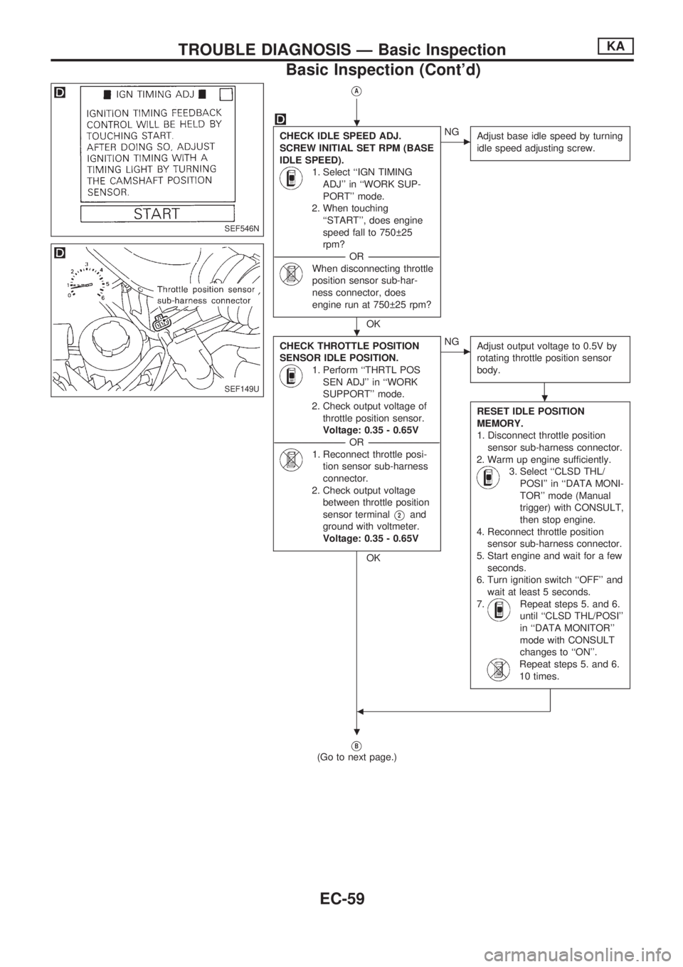
VA
CHECK IDLE SPEED ADJ.
SCREW INITIAL SET RPM (BASE
IDLE SPEED).
1. Select ``IGN TIMING
ADJ'' in ``WORK SUP-
PORT'' mode.
2. When touching
``START'', does engine
speed fall to 750 25
rpm?
-----------------------------------------------------------------------------------------------------------OR -----------------------------------------------------------------------------------------------------------
When disconnecting throttle
position sensor sub-har-
ness connector, does
engine run at 750 25 rpm?
OK
cNG
Adjust base idle speed by turning
idle speed adjusting screw.
CHECK THROTTLE POSITION
SENSOR IDLE POSITION.
1. Perform ``THRTL POS
SEN ADJ'' in ``WORK
SUPPORT'' mode.
2. Check output voltage of
throttle position sensor.
Voltage: 0.35 - 0.65V
-----------------------------------------------------------------------------------------------------------OR -----------------------------------------------------------------------------------------------------------
1. Reconnect throttle posi-
tion sensor sub-harness
connector.
2. Check output voltage
between throttle position
sensor terminal
V2and
ground with voltmeter.
Voltage: 0.35 - 0.65V
OK
cNG
Adjust output voltage to 0.5V by
rotating throttle position sensor
body.
RESET IDLE POSITION
MEMORY.
1. Disconnect throttle position
sensor sub-harness connector.
2. Warm up engine sufficiently.
3. Select ``CLSD THL/
POSI'' in ``DATA MONI-
TOR'' mode (Manual
trigger) with CONSULT,
then stop engine.
4. Reconnect throttle position
sensor sub-harness connector.
5. Start engine and wait for a few
seconds.
6. Turn ignition switch ``OFF'' and
wait at least 5 seconds.
7.
Repeat steps 5. and 6.
until ``CLSD THL/POSI''
in ``DATA MONITOR''
mode with CONSULT
changes to ``ON''.
Repeat steps 5. and 6.
10 times.
b
VB
(Go to next page.)
SEF546N
SEF149U
.
.
.
.
TROUBLE DIAGNOSIS Ð Basic InspectionKA
Basic Inspection (Cont'd)
EC-59
Page 216 of 1659
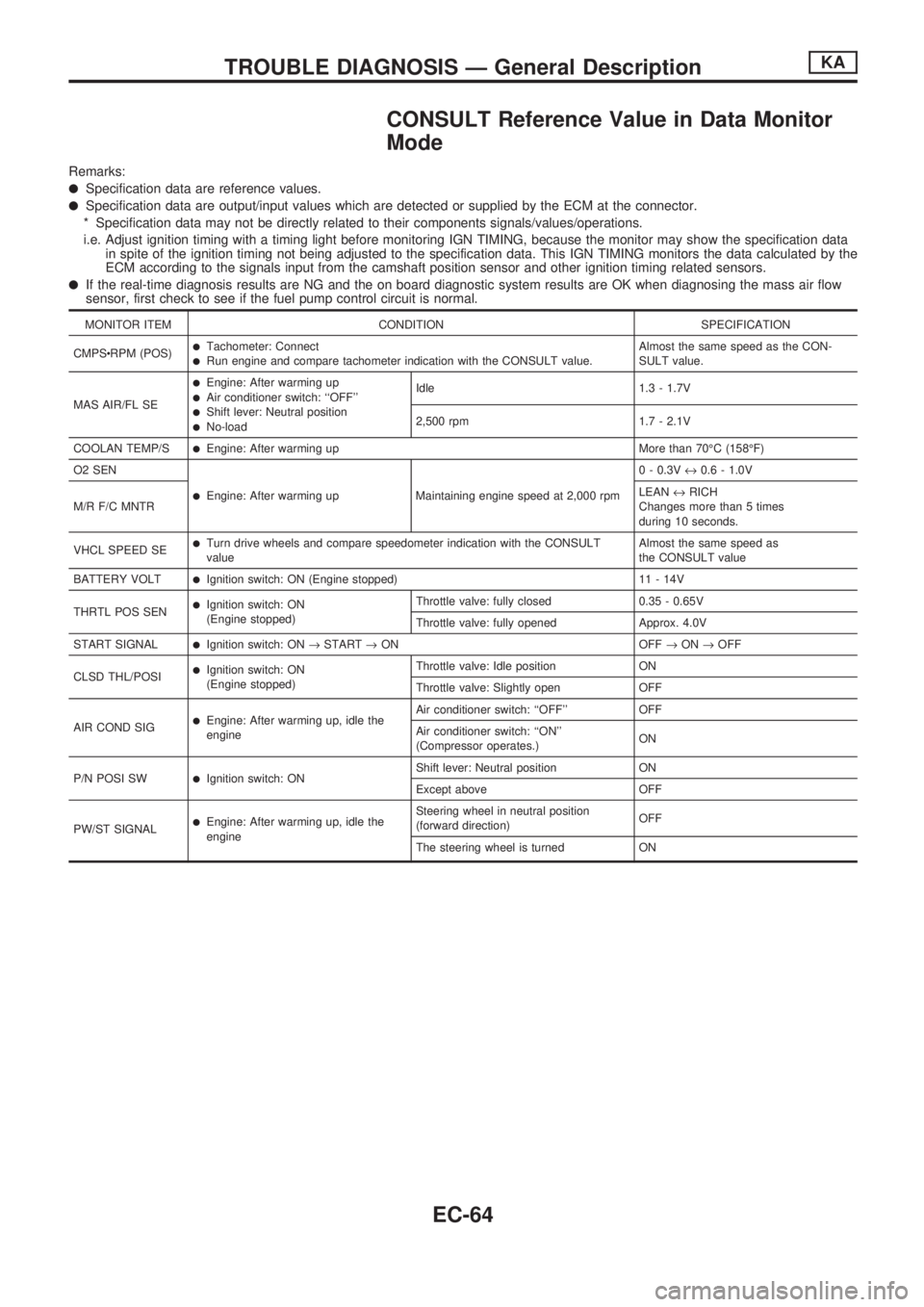
CONSULT Reference Value in Data Monitor
Mode
Remarks:
lSpecification data are reference values.
lSpecification data are output/input values which are detected or supplied by the ECM at the connector.
* Specification data may not be directly related to their components signals/values/operations.
i.e. Adjust ignition timing with a timing light before monitoring IGN TIMING, because the monitor may show the specification data
in spite of the ignition timing not being adjusted to the specification data. This IGN TIMING monitors the data calculated by the
ECM according to the signals input from the camshaft position sensor and other ignition timing related sensors.
lIf the real-time diagnosis results are NG and the on board diagnostic system results are OK when diagnosing the mass air flow
sensor, first check to see if the fuel pump control circuit is normal.
MONITOR ITEM CONDITION SPECIFICATION
CMPScRPM (POS)
lTachometer: ConnectlRun engine and compare tachometer indication with the CONSULT value.Almost the same speed as the CON-
SULT value.
MAS AIR/FL SE
lEngine: After warming uplAir conditioner switch: ``OFF''lShift lever: Neutral positionlNo-loadIdle 1.3 - 1.7V
2,500 rpm 1.7 - 2.1V
COOLAN TEMP/S
lEngine: After warming up More than 70ÉC (158ÉF)
O2 SEN
lEngine: After warming up Maintaining engine speed at 2,000 rpm0 - 0.3V«0.6 - 1.0V
M/R F/C MNTRLEAN«RICH
Changes more than 5 times
during 10 seconds.
VHCL SPEED SE
lTurn drive wheels and compare speedometer indication with the CONSULT
valueAlmost the same speed as
the CONSULT value
BATTERY VOLT
lIgnition switch: ON (Engine stopped) 11 - 14V
THRTL POS SEN
lIgnition switch: ON
(Engine stopped)Throttle valve: fully closed 0.35 - 0.65V
Throttle valve: fully opened Approx. 4.0V
START SIGNAL
lIgnition switch: ON®START®ON OFF®ON®OFF
CLSD THL/POSI
lIgnition switch: ON
(Engine stopped)Throttle valve: Idle position ON
Throttle valve: Slightly open OFF
AIR COND SIG
lEngine: After warming up, idle the
engineAir conditioner switch: ``OFF'' OFF
Air conditioner switch: ``ON''
(Compressor operates.)ON
P/N POSI SW
lIgnition switch: ONShift lever: Neutral position ON
Except above OFF
PW/ST SIGNAL
lEngine: After warming up, idle the
engineSteering wheel in neutral position
(forward direction)OFF
The steering wheel is turned ON
TROUBLE DIAGNOSIS Ð General DescriptionKA
EC-64
Page 217 of 1659
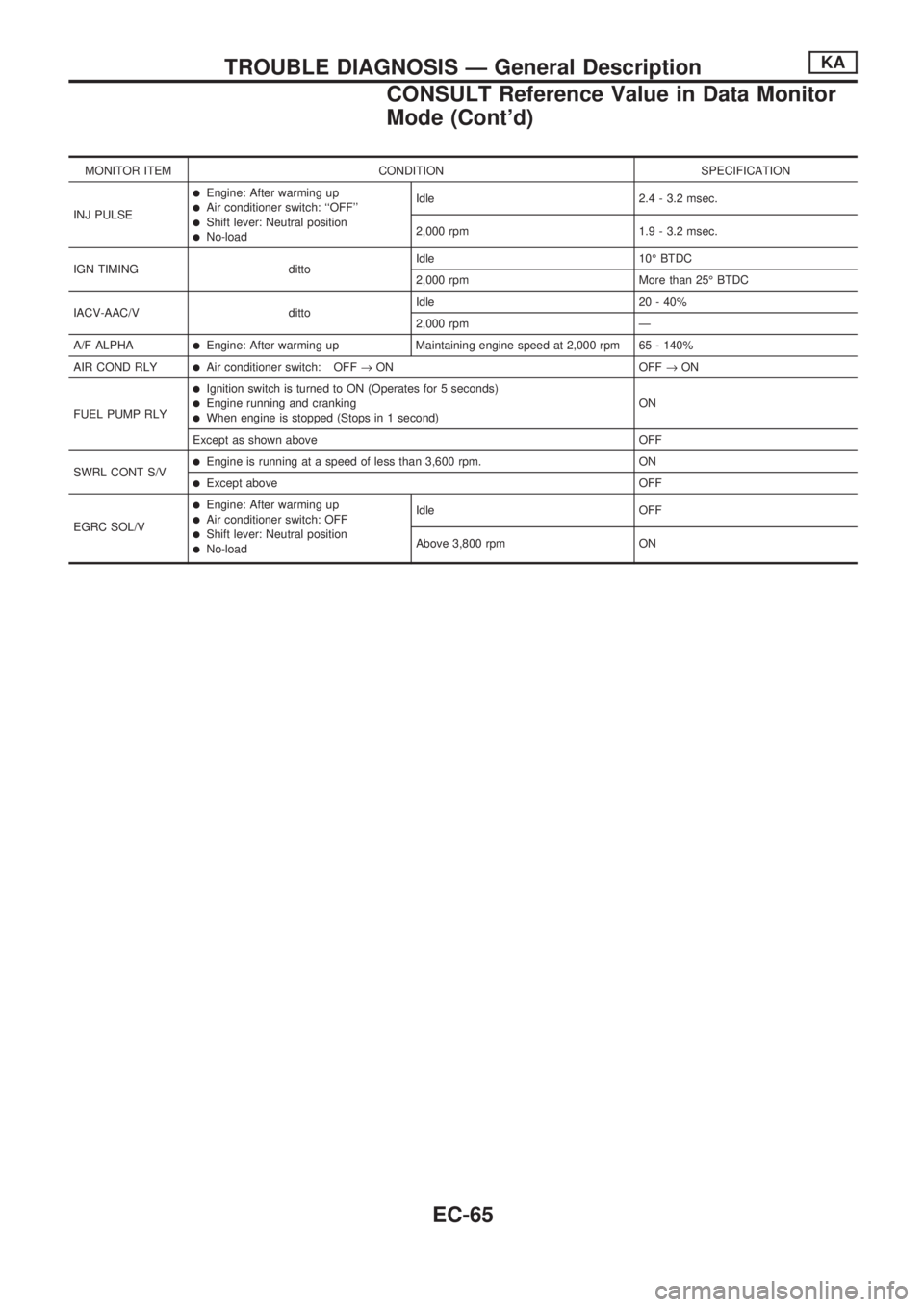
MONITOR ITEM CONDITION SPECIFICATION
INJ PULSE
lEngine: After warming uplAir conditioner switch: ``OFF''lShift lever: Neutral positionlNo-loadIdle 2.4 - 3.2 msec.
2,000 rpm 1.9 - 3.2 msec.
IGN TIMING dittoIdle 10É BTDC
2,000 rpm More than 25É BTDC
IACV-AAC/V dittoIdle 20 - 40%
2,000 rpm Ð
A/F ALPHA
lEngine: After warming up Maintaining engine speed at 2,000 rpm 65 - 140%
AIR COND RLY
lAir conditioner switch: OFF®ON OFF®ON
FUEL PUMP RLY
lIgnition switch is turned to ON (Operates for 5 seconds)lEngine running and crankinglWhen engine is stopped (Stops in 1 second)ON
Except as shown above OFF
SWRL CONT S/V
lEngine is running at a speed of less than 3,600 rpm. ON
lExcept above OFF
EGRC SOL/V
lEngine: After warming uplAir conditioner switch: OFFlShift lever: Neutral positionlNo-loadIdle OFF
Above 3,800 rpm ON
TROUBLE DIAGNOSIS Ð General DescriptionKA
CONSULT Reference Value in Data Monitor
Mode (Cont'd)
EC-65
Page 222 of 1659
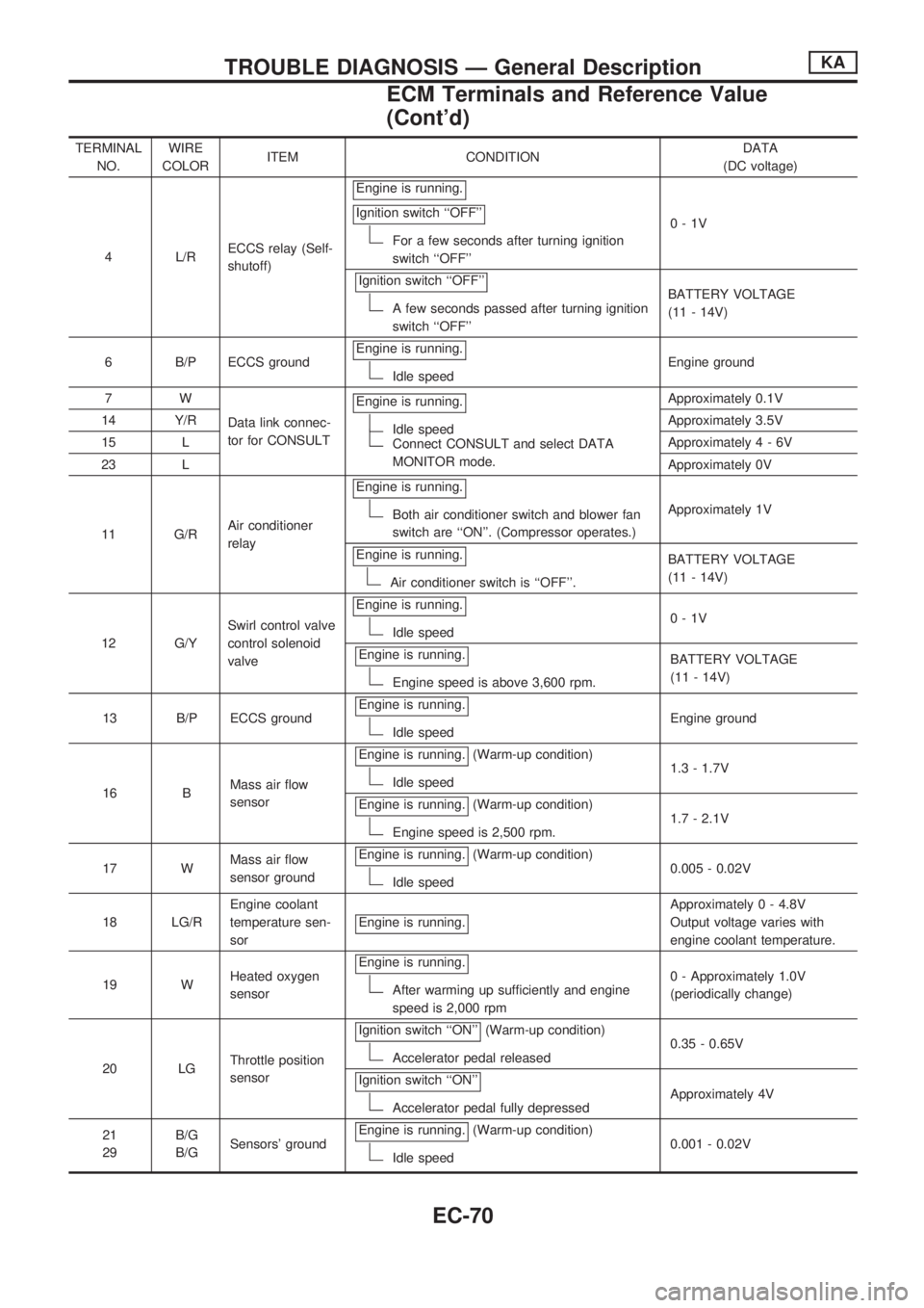
TERMINAL
NO.WIRE
COLORITEM CONDITIONDATA
(DC voltage)
4 L/RECCS relay (Self-
shutoff)Engine is running.
Ignition switch ``OFF''
For a few seconds after turning ignition
switch ``OFF''0-1V
Ignition switch ``OFF''
A few seconds passed after turning ignition
switch ``OFF''BATTERY VOLTAGE
(11 - 14V)
6 B/P ECCS groundEngine is running.
Idle speedEngine ground
7W
Data link connec-
tor for CONSULTEngine is running.
Idle speedConnect CONSULT and select DATA
MONITOR mode.Approximately 0.1V
14 Y/RApproximately 3.5V
15 LApproximately4-6V
23 LApproximately 0V
11 G/RAir conditioner
relayEngine is running.
Both air conditioner switch and blower fan
switch are ``ON''. (Compressor operates.)Approximately 1V
Engine is running.
Air conditioner switch is ``OFF''.BATTERY VOLTAGE
(11 - 14V)
12 G/YSwirl control valve
control solenoid
valveEngine is running.
Idle speed0-1V
Engine is running.
Engine speed is above 3,600 rpm.BATTERY VOLTAGE
(11 - 14V)
13 B/P ECCS groundEngine is running.
Idle speedEngine ground
16 BMass air flow
sensorEngine is running.
(Warm-up condition)
Idle speed1.3 - 1.7V
Engine is running.
(Warm-up condition)
Engine speed is 2,500 rpm.1.7 - 2.1V
17 WMass air flow
sensor groundEngine is running.
(Warm-up condition)
Idle speed0.005 - 0.02V
18 LG/REngine coolant
temperature sen-
sorEngine is running.
Approximately 0 - 4.8V
Output voltage varies with
engine coolant temperature.
19 WHeated oxygen
sensorEngine is running.
After warming up sufficiently and engine
speed is 2,000 rpm0 - Approximately 1.0V
(periodically change)
20 LGThrottle position
sensorIgnition switch ``ON''
(Warm-up condition)
Accelerator pedal released0.35 - 0.65V
Ignition switch ``ON''
Accelerator pedal fully depressedApproximately 4V
21
29B/G
B/GSensors' groundEngine is running.
(Warm-up condition)
Idle speed0.001 - 0.02V
TROUBLE DIAGNOSIS Ð General DescriptionKA
ECM Terminals and Reference Value
(Cont'd)
EC-70
Page 232 of 1659
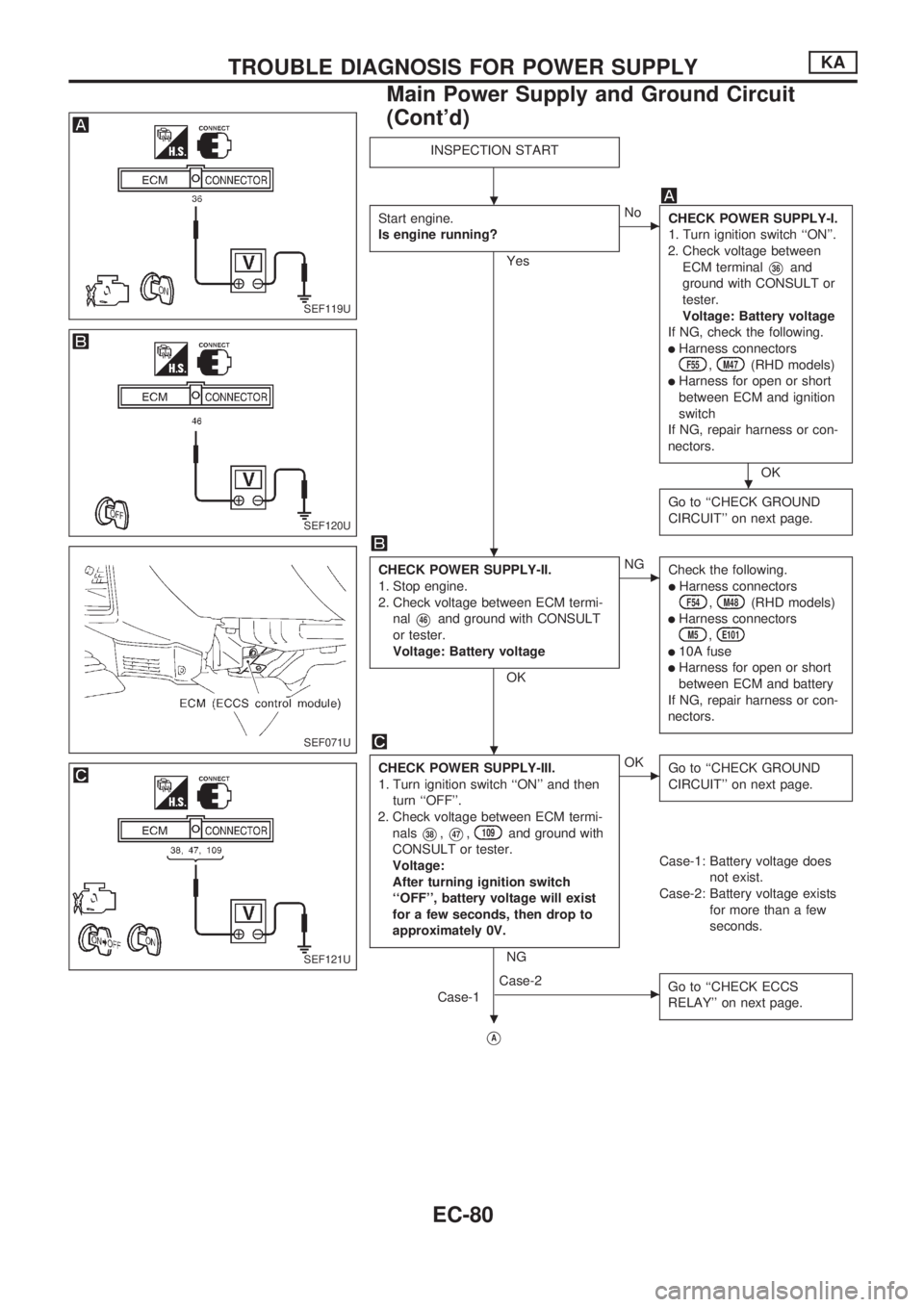
INSPECTION START
Start engine.
Is engine running?
Yes
cNo
CHECK POWER SUPPLY-I.
1. Turn ignition switch ``ON''.
2. Check voltage between
ECM terminal
V36and
ground with CONSULT or
tester.
Voltage: Battery voltage
If NG, check the following.
lHarness connectorsF55,M47(RHD models)
lHarness for open or short
between ECM and ignition
switch
If NG, repair harness or con-
nectors.
OK
Go to ``CHECK GROUND
CIRCUIT'' on next page.
CHECK POWER SUPPLY-II.
1. Stop engine.
2. Check voltage between ECM termi-
nal
V46and ground with CONSULT
or tester.
Voltage: Battery voltage
OK
cNG
Check the following.
lHarness connectorsF54,M48(RHD models)
lHarness connectorsM5,E101
l10A fuse
lHarness for open or short
between ECM and battery
If NG, repair harness or con-
nectors.
CHECK POWER SUPPLY-III.
1. Turn ignition switch ``ON'' and then
turn ``OFF''.
2. Check voltage between ECM termi-
nals
V38,V47,109and ground with
CONSULT or tester.
Voltage:
After turning ignition switch
``OFF'', battery voltage will exist
for a few seconds, then drop to
approximately 0V.
NG
cOK
Go to ``CHECK GROUND
CIRCUIT'' on next page.
Case-1: Battery voltage does
not exist.
Case-2: Battery voltage exists
for more than a few
seconds.
Case-1
cCase-2
Go to ``CHECK ECCS
RELAY'' on next page.
VA
SEF119U
SEF120U
SEF071U
SEF121U
.
.
.
.
.
TROUBLE DIAGNOSIS FOR POWER SUPPLYKA
Main Power Supply and Ground Circuit
(Cont'd)
EC-80
Page 236 of 1659
11lEither 1É or 180É signal is not sent to ECM for the first
few seconds during engine cranking.
.......................................................................................lHarness or connectors
(The camshaft position sensor circuit is open or
shorted.)
lCamshaft position sensorlStarter motor (Refer to EL section.)lStarting system circuit (Refer to EL section.)lDead (Weak) battery
lEither 1É or 180É signal is not sent to ECM during
engine running.
.......................................................................................
lEither 1É or 180É signal is not in the normal pattern
during engine running.
DIAGNOSTIC TROUBLE CODE CONFIRMATION
PROCEDURE
Before performing the following procedure, confirm that
battery voltage is more than 10V.
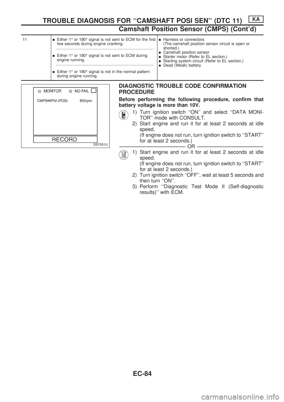
1) Turn ignition switch ``ON'' and select ``DATA MONI-
TOR'' mode with CONSULT.
2) Start engine and run it for at least 2 seconds at idle
speed.
(If engine does not run, turn ignition switch to ``START''
for at least 2 seconds.)
-------------------------------------------------------------------------------------------------------------------------------------------------------------------------------------------------------------------------------------------------OR-------------------------------------------------------------------------------------------------------------------------------------------------------------------------------------------------------------------------------------------------
1) Start engine and run it for at least 2 seconds at idle
speed.
(If engine does not run, turn ignition switch to ``START''
for at least 2 seconds.)
2) Turn ignition switch ``OFF'', wait at least 5 seconds and
then turn ``ON''.
3) Perform ``Diagnostic Test Mode II (Self-diagnostic
results)'' with ECM.
SEF051U
TROUBLE DIAGNOSIS FOR ``CAMSHAFT POSI SEN'' (DTC 11)KA
Camshaft Position Sensor (CMPS) (Cont'd)
EC-84
Page 242 of 1659

DIAGNOSTIC TROUBLE CODE CONFIRMATION
PROCEDURE
1) Turn ignition switch ``ON'', and wait at least 6 seconds.
2) Select ``DATA MONITOR'' mode with CONSULT.
3) Start engine and wait at least 3 seconds.
-------------------------------------------------------------------------------------------------------------------------------------------------------------------------------------------------------------------------------------------------OR-------------------------------------------------------------------------------------------------------------------------------------------------------------------------------------------------------------------------------------------------
1) Turn ignition switch ``ON'', and wait at least 6 seconds.
2) Start engine and wait at least 3 seconds.
3) Turn ignition switch ``OFF'', wait at least 5 seconds and
then turn ``ON''.
4) Perform ``Diagnostic Test Mode II (Self-diagnostic
results)'' with ECM.
SEF078U
TROUBLE DIAGNOSIS FOR ``MASS AIR FLOW SEN'' (DTC 12)KA
Mass Air Flow Sensor (MAFS) (Cont'd)
EC-90