1998 NISSAN PICK-UP ECO mode
[x] Cancel search: ECO modePage 247 of 1659
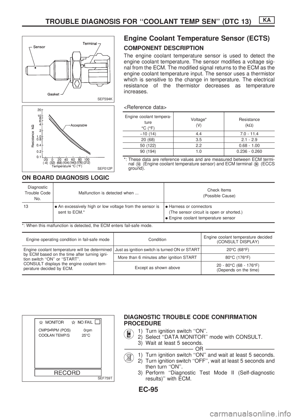
Engine Coolant Temperature Sensor (ECTS)
COMPONENT DESCRIPTION
The engine coolant temperature sensor is used to detect the
engine coolant temperature. The sensor modifies a voltage sig-
nal from the ECM. The modified signal returns to the ECM as the
engine coolant temperature input. The sensor uses a thermistor
which is sensitive to the change in temperature. The electrical
resistance of the thermistor decreases as temperature
increases.
Engine coolant tempera-
ture
ÉC (ÉF)Voltage*
(V)Resistance
(kW)
þ10 (14) 4.4 7.0 - 11.4
20 (68) 3.5 2.1 - 2.9
50 (122) 2.2 0.68 - 1.00
90 (194) 1.0 0.236 - 0.260
*: These data are reference values and are measured between ECM termi-
nal
V18(Engine coolant temperature sensor) and ECM terminalV39(ECCS
ground).
ON BOARD DIAGNOSIS LOGIC
Diagnostic
Trouble Code
No.Malfunction is detected when ...Check Items
(Possible Cause)
13
lAn excessively high or low voltage from the sensor is
sent to ECM.*lHarness or connectors
(The sensor circuit is open or shorted.)
lEngine coolant temperature sensor
*: When this malfunction is detected, the ECM enters fail-safe mode.
Engine operating condition in fail-safe mode ConditionEngine coolant temperature decided
(CONSULT DISPLAY)
Engine coolant temperature will be determined
by ECM based on the time after turning igni-
tion switch ``ON'' or ``START''.
CONSULT displays the engine coolant tem-
perature decided by ECM.Just as ignition switch is turned ON or START 20ÉC (68ÉF)
More than 6 minutes after ignition START 80ÉC (176ÉF)
Except as shown above20 - 80ÉC (68 - 176ÉF)
(Depends on the time)
DIAGNOSTIC TROUBLE CODE CONFIRMATION
PROCEDURE
1) Turn ignition switch ``ON''.
2) Select ``DATA MONITOR'' mode with CONSULT.
3) Wait at least 5 seconds.
-------------------------------------------------------------------------------------------------------------------------------------------------------------------------------------------------------------------------------------------------OR-------------------------------------------------------------------------------------------------------------------------------------------------------------------------------------------------------------------------------------------------
1) Turn ignition switch ``ON'' and wait at least 5 seconds.
2) Turn ignition switch ``OFF'', wait at least 5 seconds and
then turn ``ON''.
3) Perform ``Diagnostic Test Mode II (Self-diagnostic
results)'' with ECM.
SEF594K
SEF012P
SEF759T
TROUBLE DIAGNOSIS FOR ``COOLANT TEMP SEN'' (DTC 13)KA
EC-95
Page 251 of 1659
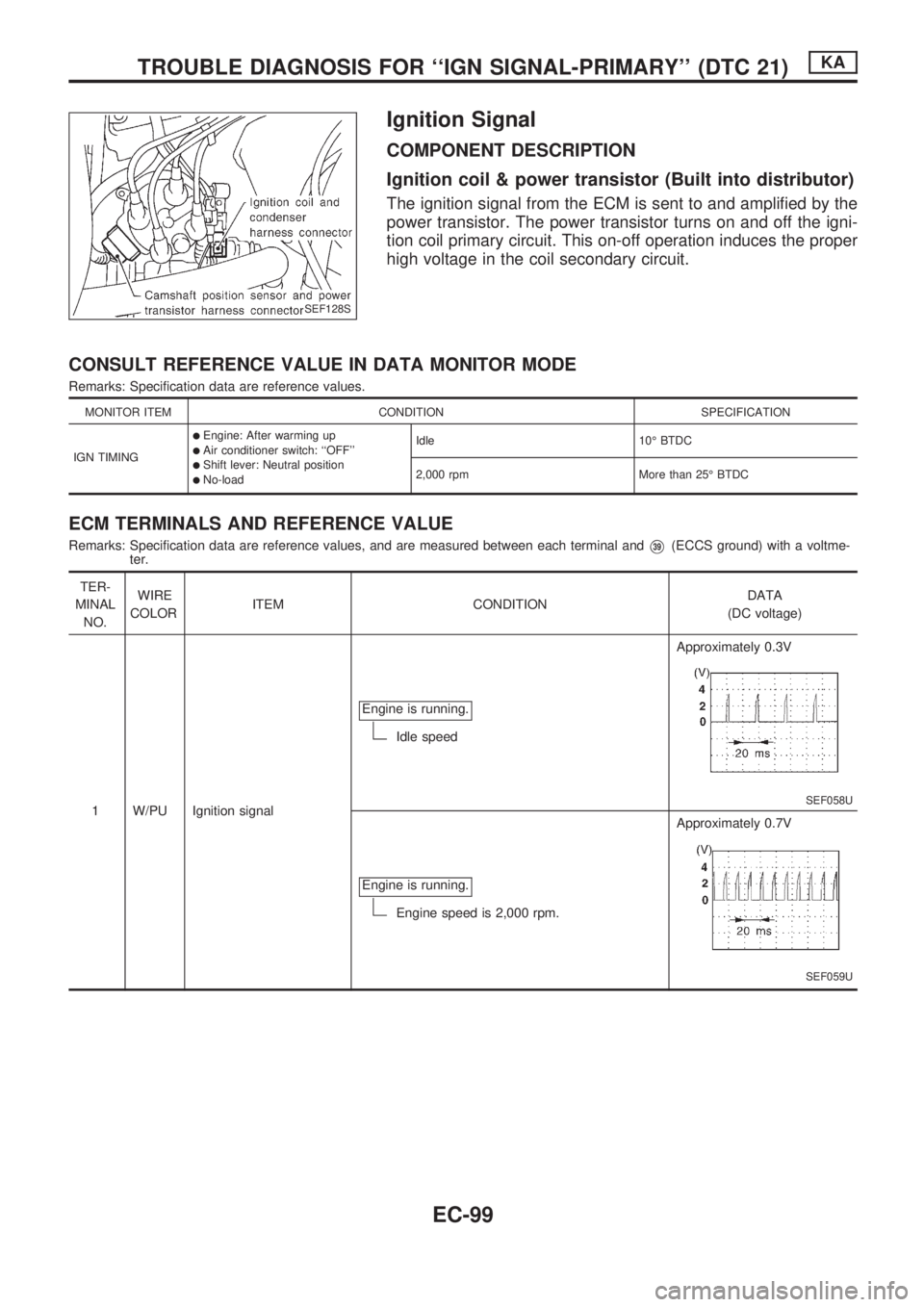
Ignition Signal
COMPONENT DESCRIPTION
Ignition coil & power transistor (Built into distributor)
The ignition signal from the ECM is sent to and amplified by the
power transistor. The power transistor turns on and off the igni-
tion coil primary circuit. This on-off operation induces the proper
high voltage in the coil secondary circuit.
CONSULT REFERENCE VALUE IN DATA MONITOR MODE
Remarks: Specification data are reference values.
MONITOR ITEM CONDITION SPECIFICATION
IGN TIMING
lEngine: After warming uplAir conditioner switch: ``OFF''lShift lever: Neutral positionlNo-loadIdle 10É BTDC
2,000 rpm More than 25É BTDC
ECM TERMINALS AND REFERENCE VALUE
Remarks: Specification data are reference values, and are measured between each terminal andV39(ECCS ground) with a voltme-
ter.
TER-
MINAL
NO.WIRE
COLORITEM CONDITIONDATA
(DC voltage)
1 W/PU Ignition signalEngine is running.
Idle speedApproximately 0.3V
SEF058U
Engine is running.
Engine speed is 2,000 rpm.Approximately 0.7V
SEF059U
SEF128S
TROUBLE DIAGNOSIS FOR ``IGN SIGNAL-PRIMARY'' (DTC 21)KA
EC-99
Page 252 of 1659
TER-
MINAL
NO.WIRE
COLORITEM CONDITIONDATA
(DC voltage)
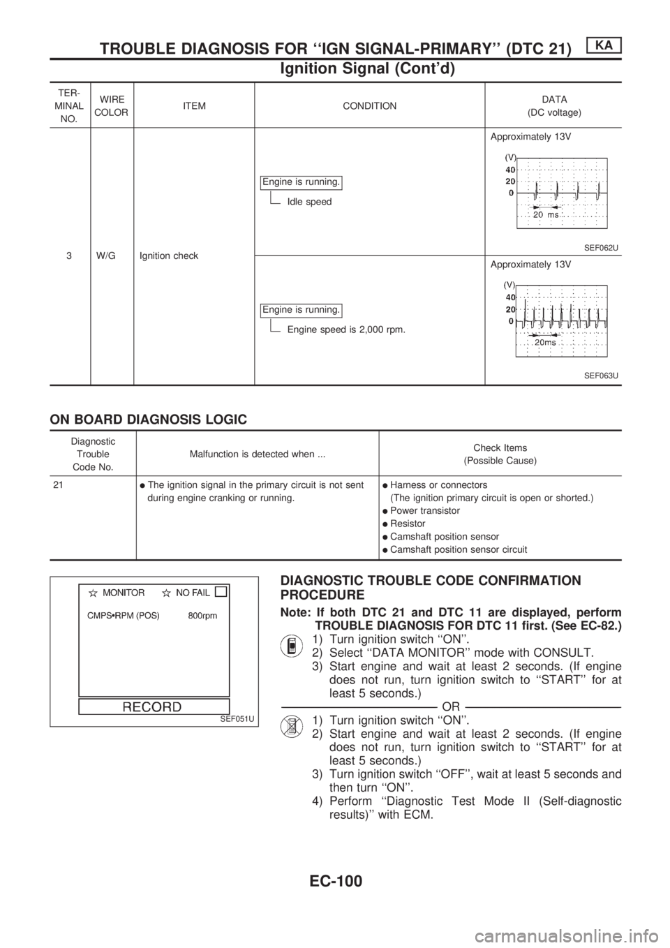
3 W/G Ignition checkEngine is running.
Idle speedApproximately 13V
SEF062U
Engine is running.
Engine speed is 2,000 rpm.Approximately 13V
SEF063U
ON BOARD DIAGNOSIS LOGIC
Diagnostic
Trouble
Code No.Malfunction is detected when ...Check Items
(Possible Cause)
21
lThe ignition signal in the primary circuit is not sent
during engine cranking or running.lHarness or connectors
(The ignition primary circuit is open or shorted.)
lPower transistor
lResistor
lCamshaft position sensor
lCamshaft position sensor circuit
DIAGNOSTIC TROUBLE CODE CONFIRMATION
PROCEDURE
Note: If both DTC 21 and DTC 11 are displayed, perform
TROUBLE DIAGNOSIS FOR DTC 11 first. (See EC-82.)
1) Turn ignition switch ``ON''.
2) Select ``DATA MONITOR'' mode with CONSULT.
3) Start engine and wait at least 2 seconds. (If engine
does not run, turn ignition switch to ``START'' for at
least 5 seconds.)
-------------------------------------------------------------------------------------------------------------------------------------------------------------------------------------------------------------------------------------------------OR-------------------------------------------------------------------------------------------------------------------------------------------------------------------------------------------------------------------------------------------------
1) Turn ignition switch ``ON''.
2) Start engine and wait at least 2 seconds. (If engine
does not run, turn ignition switch to ``START'' for at
least 5 seconds.)
3) Turn ignition switch ``OFF'', wait at least 5 seconds and
then turn ``ON''.
4) Perform ``Diagnostic Test Mode II (Self-diagnostic
results)'' with ECM.SEF051U
TROUBLE DIAGNOSIS FOR ``IGN SIGNAL-PRIMARY'' (DTC 21)KA
Ignition Signal (Cont'd)
EC-100
Page 261 of 1659
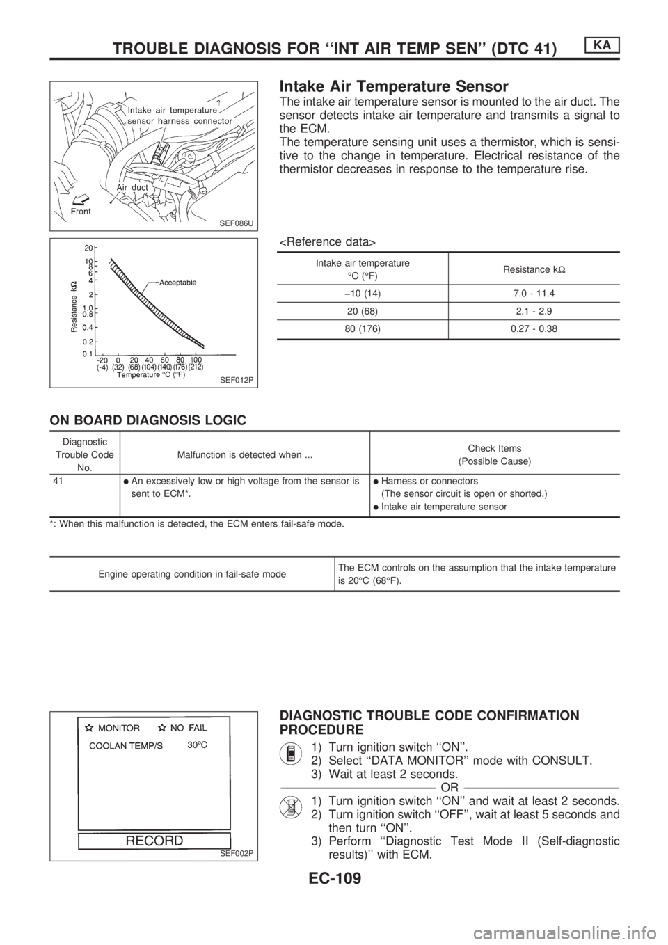
Intake Air Temperature Sensor
The intake air temperature sensor is mounted to the air duct. The
sensor detects intake air temperature and transmits a signal to
the ECM.
The temperature sensing unit uses a thermistor, which is sensi-
tive to the change in temperature. Electrical resistance of the
thermistor decreases in response to the temperature rise.
Intake air temperature
ÉC (ÉF)Resistance kW
þ10 (14) 7.0 - 11.4
20 (68) 2.1 - 2.9
80 (176) 0.27 - 0.38
ON BOARD DIAGNOSIS LOGIC
Diagnostic
Trouble Code
No.Malfunction is detected when ...Check Items
(Possible Cause)
41
lAn excessively low or high voltage from the sensor is
sent to ECM*.lHarness or connectors
(The sensor circuit is open or shorted.)
lIntake air temperature sensor
*: When this malfunction is detected, the ECM enters fail-safe mode.
Engine operating condition in fail-safe modeThe ECM controls on the assumption that the intake temperature
is 20ÉC (68ÉF).
DIAGNOSTIC TROUBLE CODE CONFIRMATION
PROCEDURE
1) Turn ignition switch ``ON''.
2) Select ``DATA MONITOR'' mode with CONSULT.
3) Wait at least 2 seconds.
-------------------------------------------------------------------------------------------------------------------------------------------------------------------------------------------------------------------------------------------------OR-------------------------------------------------------------------------------------------------------------------------------------------------------------------------------------------------------------------------------------------------
1) Turn ignition switch ``ON'' and wait at least 2 seconds.
2) Turn ignition switch ``OFF'', wait at least 5 seconds and
then turn ``ON''.
3) Perform ``Diagnostic Test Mode II (Self-diagnostic
results)'' with ECM.
SEF086U
SEF012P
SEF002P
TROUBLE DIAGNOSIS FOR ``INT AIR TEMP SEN'' (DTC 41)KA
EC-109
Page 266 of 1659
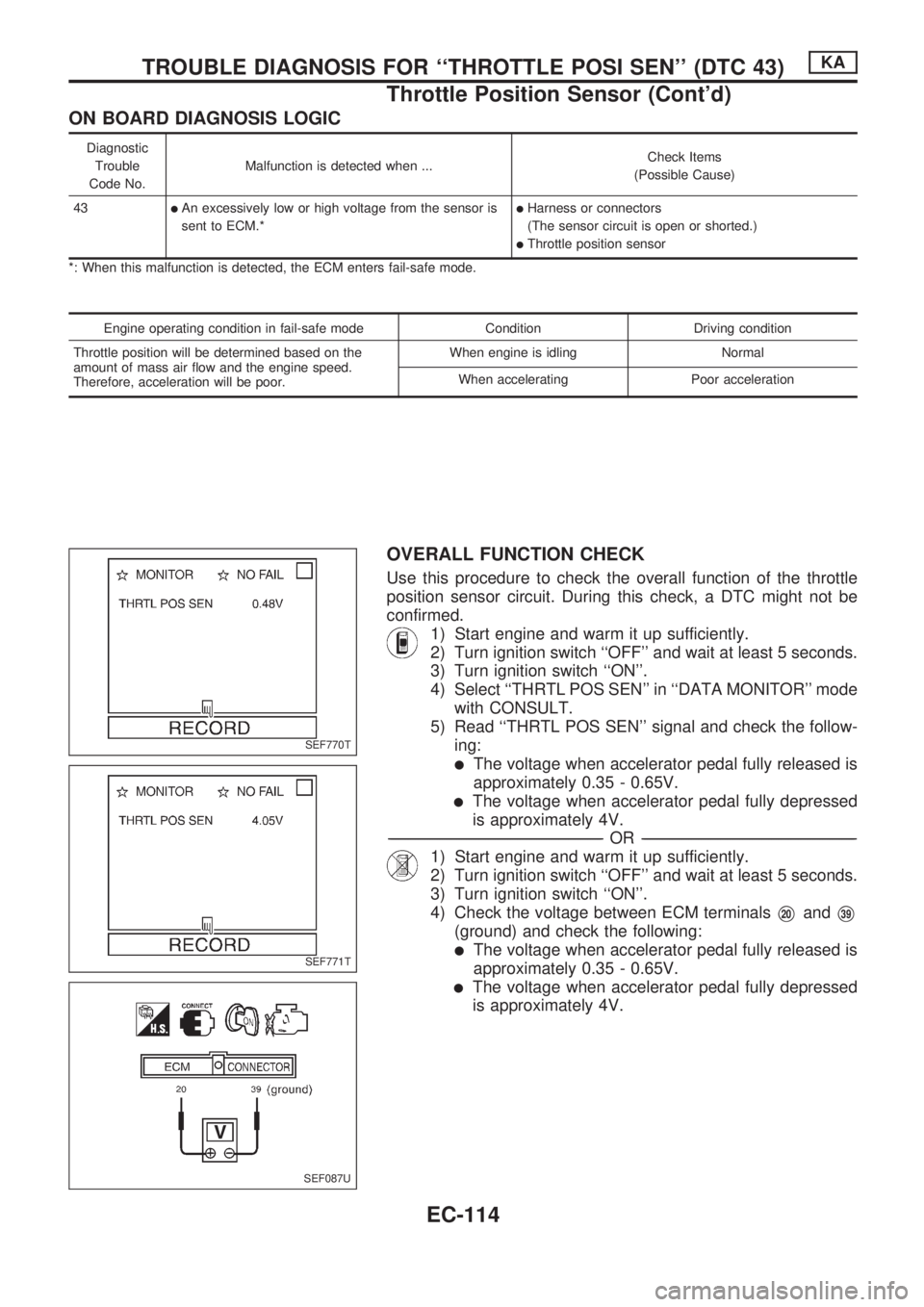
ON BOARD DIAGNOSIS LOGIC
Diagnostic
Trouble
Code No.Malfunction is detected when ...Check Items
(Possible Cause)
43
lAn excessively low or high voltage from the sensor is
sent to ECM.*lHarness or connectors
(The sensor circuit is open or shorted.)
lThrottle position sensor
*: When this malfunction is detected, the ECM enters fail-safe mode.
Engine operating condition in fail-safe mode Condition Driving condition
Throttle position will be determined based on the
amount of mass air flow and the engine speed.
Therefore, acceleration will be poor.When engine is idling Normal
When accelerating Poor acceleration
OVERALL FUNCTION CHECK
Use this procedure to check the overall function of the throttle
position sensor circuit. During this check, a DTC might not be
confirmed.
1) Start engine and warm it up sufficiently.
2) Turn ignition switch ``OFF'' and wait at least 5 seconds.
3) Turn ignition switch ``ON''.
4) Select ``THRTL POS SEN'' in ``DATA MONITOR'' mode
with CONSULT.
5) Read ``THRTL POS SEN'' signal and check the follow-
ing:
lThe voltage when accelerator pedal fully released is
approximately 0.35 - 0.65V.
lThe voltage when accelerator pedal fully depressed
is approximately 4V.
-------------------------------------------------------------------------------------------------------------------------------------------------------------------------------------------------------------------------------------------------OR-------------------------------------------------------------------------------------------------------------------------------------------------------------------------------------------------------------------------------------------------
1) Start engine and warm it up sufficiently.
2) Turn ignition switch ``OFF'' and wait at least 5 seconds.
3) Turn ignition switch ``ON''.
4) Check the voltage between ECM terminals
V20andV39
(ground) and check the following:
lThe voltage when accelerator pedal fully released is
approximately 0.35 - 0.65V.
lThe voltage when accelerator pedal fully depressed
is approximately 4V.
SEF770T
SEF771T
SEF087U
TROUBLE DIAGNOSIS FOR ``THROTTLE POSI SEN'' (DTC 43)KA
Throttle Position Sensor (Cont'd)
EC-114
Page 269 of 1659
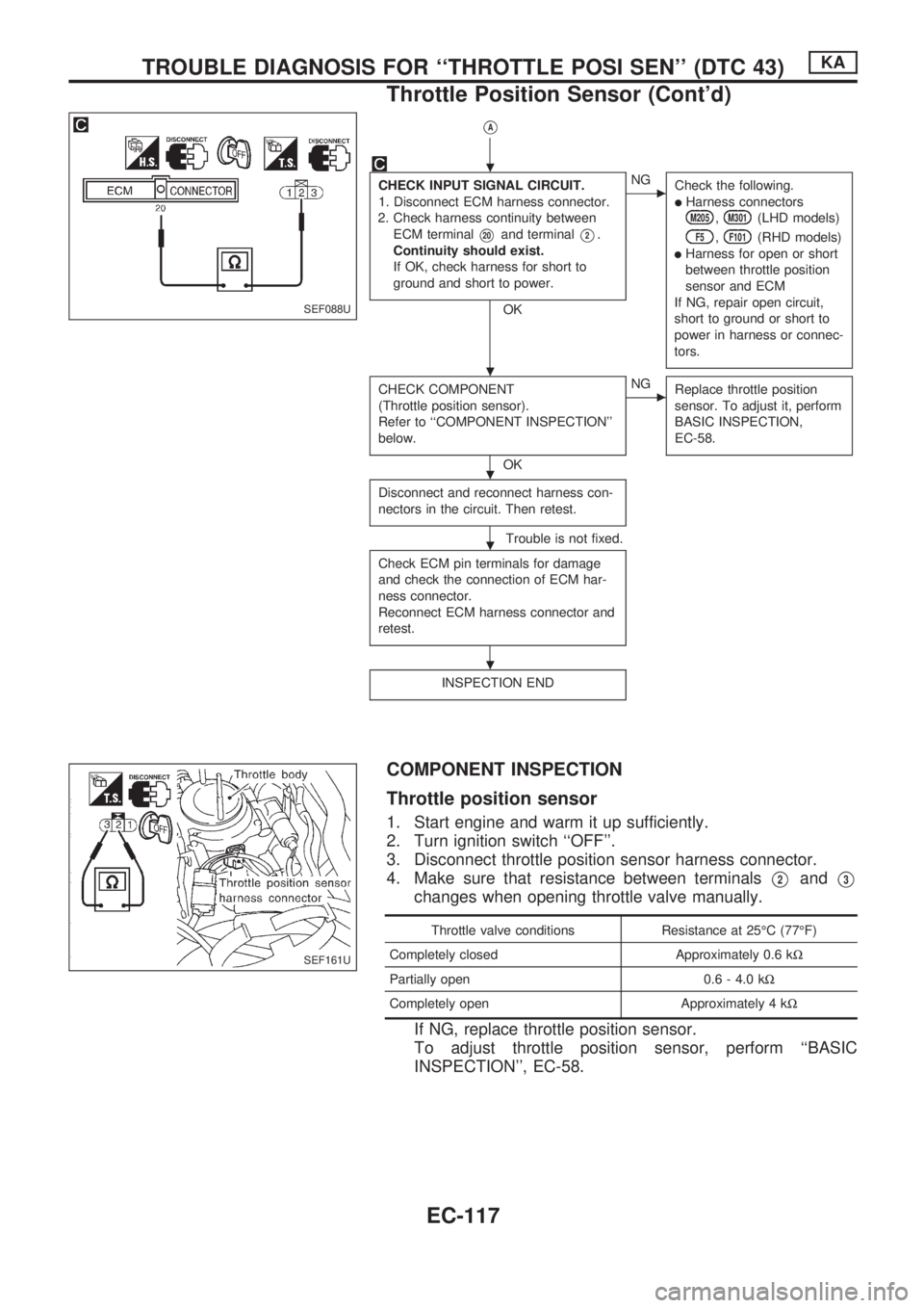
VA
CHECK INPUT SIGNAL CIRCUIT.
1. Disconnect ECM harness connector.
2. Check harness continuity between
ECM terminal
V20and terminalV2.
Continuity should exist.
If OK, check harness for short to
ground and short to power.
OK
cNG
Check the following.
lHarness connectorsM205,M301(LHD models)
F5,F101(RHD models)
lHarness for open or short
between throttle position
sensor and ECM
If NG, repair open circuit,
short to ground or short to
power in harness or connec-
tors.
CHECK COMPONENT
(Throttle position sensor).
Refer to ``COMPONENT INSPECTION''
below.
OK
cNG
Replace throttle position
sensor. To adjust it, perform
BASIC INSPECTION,
EC-58.
Disconnect and reconnect harness con-
nectors in the circuit. Then retest.
Trouble is not fixed.
Check ECM pin terminals for damage
and check the connection of ECM har-
ness connector.
Reconnect ECM harness connector and
retest.
INSPECTION END
COMPONENT INSPECTION
Throttle position sensor
1. Start engine and warm it up sufficiently.
2. Turn ignition switch ``OFF''.
3. Disconnect throttle position sensor harness connector.
4. Make sure that resistance between terminals
V2andV3
changes when opening throttle valve manually.
Throttle valve conditions Resistance at 25ÉC (77ÉF)
Completely closed Approximately 0.6 kW
Partially open 0.6 - 4.0 kW
Completely open Approximately 4 kW
If NG, replace throttle position sensor.
To adjust throttle position sensor, perform ``BASIC
INSPECTION'', EC-58.
SEF088U
SEF161U
.
.
.
.
.
TROUBLE DIAGNOSIS FOR ``THROTTLE POSI SEN'' (DTC 43)KA
Throttle Position Sensor (Cont'd)
EC-117
Page 277 of 1659
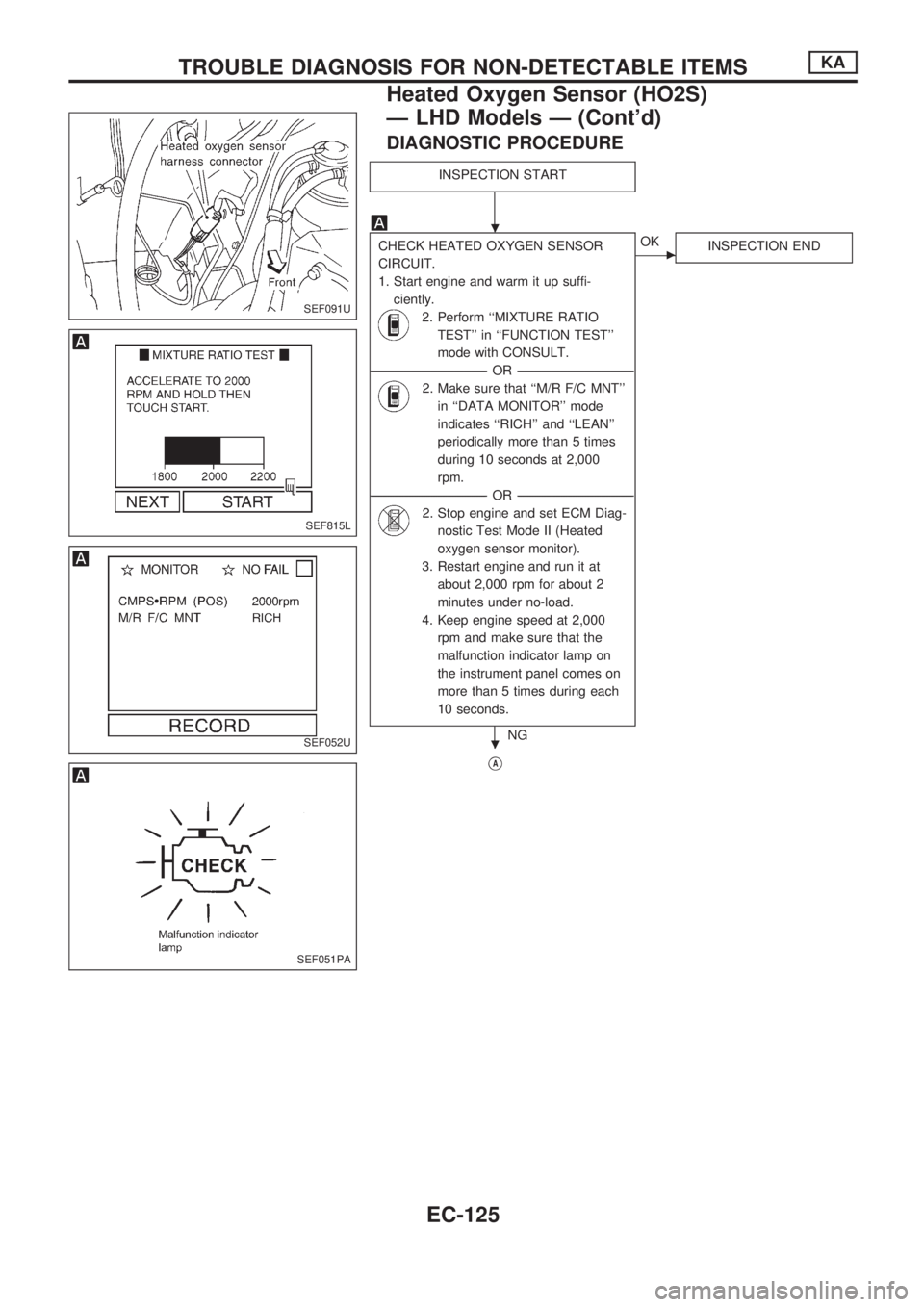
DIAGNOSTIC PROCEDURE
INSPECTION START
CHECK HEATED OXYGEN SENSOR
CIRCUIT.
1. Start engine and warm it up suffi-
ciently.
2. Perform ``MIXTURE RATIO
TEST'' in ``FUNCTION TEST''
mode with CONSULT.
----------------------------------------------------------------------------------------------------------------------------------OR----------------------------------------------------------------------------------------------------------------------------------
2. Make sure that ``M/R F/C MNT''
in ``DATA MONITOR'' mode
indicates ``RICH'' and ``LEAN''
periodically more than 5 times
during 10 seconds at 2,000
rpm.
----------------------------------------------------------------------------------------------------------------------------------OR----------------------------------------------------------------------------------------------------------------------------------
2. Stop engine and set ECM Diag-
nostic Test Mode II (Heated
oxygen sensor monitor).
3. Restart engine and run it at
about 2,000 rpm for about 2
minutes under no-load.
4. Keep engine speed at 2,000
rpm and make sure that the
malfunction indicator lamp on
the instrument panel comes on
more than 5 times during each
10 seconds.
NG
cOK
INSPECTION END
VA
SEF091U
SEF815L
SEF052U
SEF051PA
.
.
TROUBLE DIAGNOSIS FOR NON-DETECTABLE ITEMSKA
Heated Oxygen Sensor (HO2S)
Ð LHD Models Ð (Cont'd)
EC-125
Page 278 of 1659
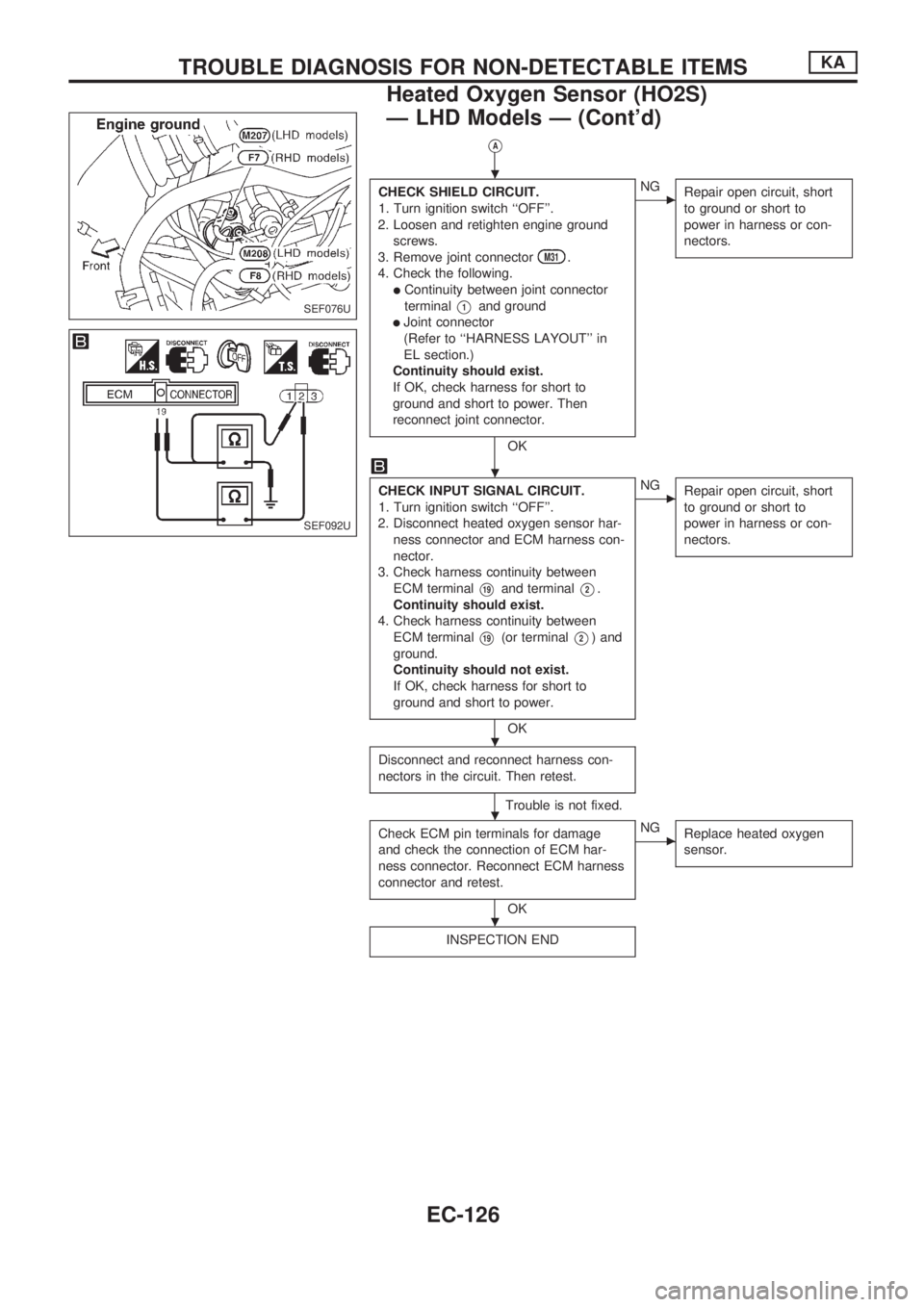
VA
CHECK SHIELD CIRCUIT.
1. Turn ignition switch ``OFF''.
2. Loosen and retighten engine ground
screws.
3. Remove joint connector
M31.
4. Check the following.
lContinuity between joint connector
terminal
V1and ground
lJoint connector
(Refer to ``HARNESS LAYOUT'' in
EL section.)
Continuity should exist.
If OK, check harness for short to
ground and short to power. Then
reconnect joint connector.
OK
cNG
Repair open circuit, short
to ground or short to
power in harness or con-
nectors.
CHECK INPUT SIGNAL CIRCUIT.
1. Turn ignition switch ``OFF''.
2. Disconnect heated oxygen sensor har-
ness connector and ECM harness con-
nector.
3. Check harness continuity between
ECM terminal
V19and terminalV2.
Continuity should exist.
4. Check harness continuity between
ECM terminal
V19(or terminalV2) and
ground.
Continuity should not exist.
If OK, check harness for short to
ground and short to power.
OK
cNG
Repair open circuit, short
to ground or short to
power in harness or con-
nectors.
Disconnect and reconnect harness con-
nectors in the circuit. Then retest.
Trouble is not fixed.
Check ECM pin terminals for damage
and check the connection of ECM har-
ness connector. Reconnect ECM harness
connector and retest.
OK
cNG
Replace heated oxygen
sensor.
INSPECTION END
SEF076U
SEF092U
.
.
.
.
.
TROUBLE DIAGNOSIS FOR NON-DETECTABLE ITEMSKA
Heated Oxygen Sensor (HO2S)
Ð LHD Models Ð (Cont'd)
EC-126