1998 NISSAN PICK-UP ECO mode
[x] Cancel search: ECO modePage 1223 of 1659
Supplemental Restraint System (SRS) ``AIR
BAG'' (4WD models)
The Supplemental Restraint System ``Air Bag'', used along with a seat belt, helps to reduce the risk or
severity of injury to the driver in a frontal collision. The Supplemental Restraint System consists of an air
bag module (located in the center of the steering wheel), a diagnosis sensor unit, warning lamp, wiring har-
ness and spiral cable. Information necessary to service the system safely is included in theRS sectionof
this Service Manual.
WARNING:
lTo avoid rendering the SRS inoperative, which could increase the risk of personal injury or death
in the event of a collision which would result in air bag inflation, all maintenance must be per-
formed by an authorized NISSAN dealer.
lImproper maintenance, including incorrect removal and installation of the SRS, can lead to per-
sonal injury caused by unintentional activation of the system.
lDo not use electrical test equipment on any circuit related to the SRS unless instructed to in this
Service Manual. SRS wiring harnesses are covered with yellow insulation either just before the
harness connectors or for the complete harness, for easy identification.
Supplemental Restraint System (SRS) ``AIR
BAG'' (2WD models)
The Supplemental Restraint System ``Air Bag'', used along with a seat belt, helps to reduce the risk or
severity of injury to the driver in a frontal collision. The Supplemental Restraint System consists of an air
bag module (located in the center of the steering wheel), a diagnosis sensor unit, warning lamp and spiral
cable. Information necessary to service the system safely is included in theRS sectionof this Service
Manual.
WARNING:
lTo avoid rendering the SRS inoperative, which could increase the risk of personal injury or death
in the event of a collision which would result in air bag inflation, all maintenance must be per-
formed by an authorized NISSAN dealer.
lImproper maintenance, including incorrect removal and installation of the SRS, can lead to per-
sonal injury caused by unintentional activation of the system.
lDo not use electrical test equipment on any circuit related to the SRS.
Precautions for Steering System
lBefore disassembly, thoroughly clean the outside of the unit.
lDisassembly should be done in a clean work area. It is important to prevent the internal parts
from becoming contaminated by dirt or other foreign matter.
lFor easier and proper assembly, place disassembled parts in order on a parts rack.
lUse nylon cloths or paper towels to clean the parts; common shop rags can leave lint that might
interfere with their operation.
lBefore inspection or reassembly, carefully clean all parts with a general purpose, non-flammable
solvent.
lBefore assembly, apply a coat of recommended ATF* to hydraulic parts. Petroleum jelly may be
applied to O-rings and seals. Do not use any grease.
lReplace all gaskets, seals and O-rings. Avoid damaging O-rings, seals and gaskets during instal-
lation. Perform functional tests whenever designated.
*: Automatic Transmission Fluid type DEXRON
TMII E, DEXRONTMIII, or equivalent.
PRECAUTIONS AND PREPARATION
ST-1
Page 1295 of 1659
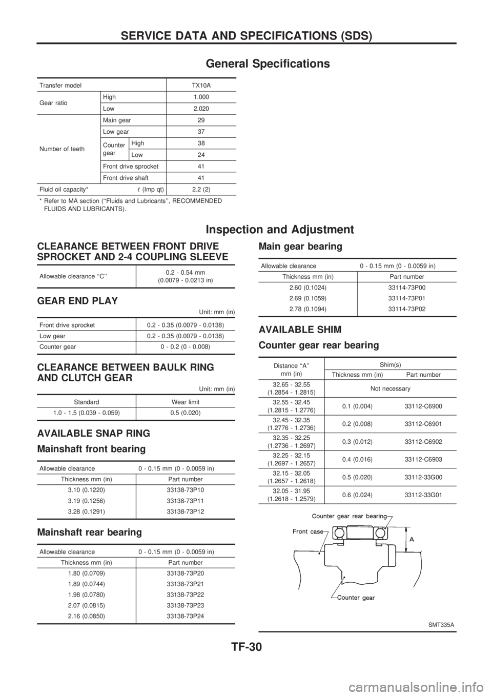
General Specifications
Transfer model TX10A
Gear ratioHigh 1.000
Low 2.020
Number of teethMain gear 29
Low gear 37
Counter
gearHigh 38
Low 24
Front drive sprocket 41
Front drive shaft 41
Fluid oil capacity*!(Imp qt) 2.2 (2)
* Refer to MA section (``Fluids and Lubricants'', RECOMMENDED
FLUIDS AND LUBRICANTS).
Inspection and Adjustment
CLEARANCE BETWEEN FRONT DRIVE
SPROCKET AND 2-4 COUPLING SLEEVE
Allowable clearance ``C''0.2 - 0.54 mm
(0.0079 - 0.0213 in)
GEAR END PLAY
Unit: mm (in)
Front drive sprocket 0.2 - 0.35 (0.0079 - 0.0138)
Low gear 0.2 - 0.35 (0.0079 - 0.0138)
Counter gear 0 - 0.2 (0 - 0.008)
CLEARANCE BETWEEN BAULK RING
AND CLUTCH GEAR
Unit: mm (in)
Standard Wear limit
1.0 - 1.5 (0.039 - 0.059) 0.5 (0.020)
AVAILABLE SNAP RING
Mainshaft front bearing
Allowable clearance 0 - 0.15 mm (0 - 0.0059 in)
Thickness mm (in) Part number
3.10 (0.1220) 33138-73P10
3.19 (0.1256) 33138-73P11
3.28 (0.1291) 33138-73P12
Mainshaft rear bearing
Allowable clearance 0 - 0.15 mm (0 - 0.0059 in)
Thickness mm (in) Part number
1.80 (0.0709) 33138-73P20
1.89 (0.0744) 33138-73P21
1.98 (0.0780) 33138-73P22
2.07 (0.0815) 33138-73P23
2.16 (0.0850) 33138-73P24
Main gear bearing
Allowable clearance 0 - 0.15 mm (0 - 0.0059 in)
Thickness mm (in) Part number
2.60 (0.1024) 33114-73P00
2.69 (0.1059) 33114-73P01
2.78 (0.1094) 33114-73P02
AVAILABLE SHIM
Counter gear rear bearing
Distance ``A''
mm (in)Shim(s)
Thickness mm (in) Part number
32.65 - 32.55
(1.2854 - 1.2815)Not necessary
32.55 - 32.45
(1.2815 - 1.2776)0.1 (0.004) 33112-C6900
32.45 - 32.35
(1.2776 - 1.2736)0.2 (0.008) 33112-C6901
32.35 - 32.25
(1.2736 - 1.2697)0.3 (0.012) 33112-C6902
32.25 - 32.15
(1.2697 - 1.2657)0.4 (0.016) 33112-C6903
32.15 - 32.05
(1.2657 - 1.2618)0.5 (0.020) 33112-33G00
32.05 - 31.95
(1.2618 - 1.2579)0.6 (0.024) 33112-33G01
SMT335A
SERVICE DATA AND SPECIFICATIONS (SDS)
TF-30
Page 1394 of 1659
Unified Control Meter System Description
UNIFIED CONTROL METER
Speedometer, odo/trip meter, tachometer, fuel gauge and water
temperature gauge are controlled totally by control unit combined
with speedometer.
Meter/gauge Operation and Odo/Trip Meter
Segment Check in Diagnosis Mode
DIAGNOSIS FUNCTION
lOdo/trip meter segment can be checked in diagnosis mode.
lMeters/gauges can be checked in diagnosis mode.
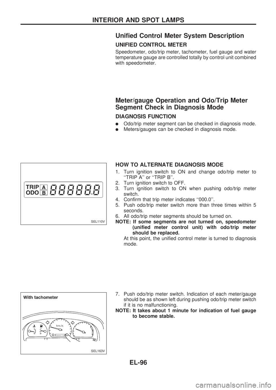
HOW TO ALTERNATE DIAGNOSIS MODE
1. Turn ignition switch to ON and change odo/trip meter to
``TRIP A'' or ``TRIP B''.
2. Turn ignition switch to OFF.
3. Turn ignition switch to ON when pushing odo/trip meter
switch.
4. Confirm that trip meter indicates ``000.0''.
5. Push odo/trip meter switch more than three times within 5
seconds.
6. All odo/trip meter segments should be turned on.
NOTE: If some segments are not turned on, speedometer
(unified meter control unit) with odo/trip meter
should be replaced.
At this point, the unified control meter is turned to diagnosis
mode.
7. Push odo/trip meter switch. Indication of each meter/gauge
should be as shown left during pushing odo/trip meter switch
if it is no malfunctioning.
NOTE: It takes about 1 minute for indication of fuel gauge
to become stable.
SEL110V
SEL163V
INTERIOR AND SPOT LAMPS
EL-96
Page 1396 of 1659
Trouble Diagnoses
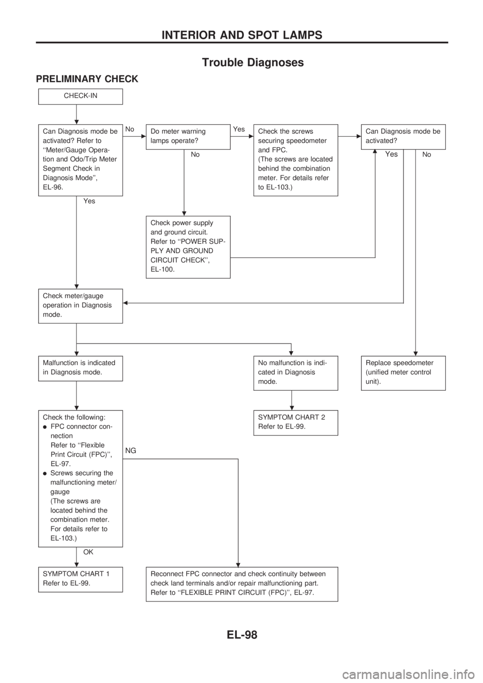
PRELIMINARY CHECK
CHECK-IN
Can Diagnosis mode be
activated? Refer to
``Meter/Gauge Opera-
tion and Odo/Trip Meter
Segment Check in
Diagnosis Mode'',
EL-96.
Yes
cNo
Do meter warning
lamps operate?
No
cYes
Check the screws
securing speedometer
and FPC.
(The screws are located
behind the combination
meter. For details refer
to EL-103.)cCan Diagnosis mode be
activated?
Nom
Check power supply
and ground circuit.
Refer to ``POWER SUP-
PLY AND GROUND
CIRCUIT CHECK'',
EL-100.
Check meter/gauge
operation in Diagnosis
mode.b
Yes
.
Malfunction is indicated
in Diagnosis mode.No malfunction is indi-
cated in Diagnosis
mode.Replace speedometer
(unified meter control
unit).
Check the following:
lFPC connector con-
nection
Refer to ``Flexible
Print Circuit (FPC)'',
EL-97.
lScrews securing the
malfunctioning meter/
gauge
(The screws are
located behind the
combination meter.
For details refer to
EL-103.)
OK
.
NG
SYMPTOM CHART 2
Refer to EL-99.
SYMPTOM CHART 1
Refer to EL-99.Reconnect FPC connector and check continuity between
check land terminals and/or repair malfunctioning part.
Refer to ``FLEXIBLE PRINT CIRCUIT (FPC)'', EL-97.
.
.
.
..
..
.
INTERIOR AND SPOT LAMPS
EL-98
Page 1418 of 1659
System Description
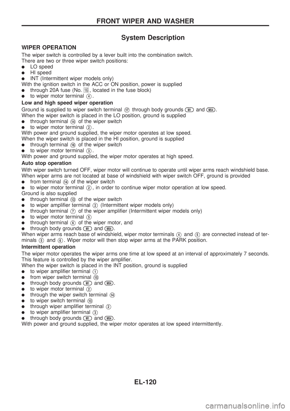
WIPER OPERATION
The wiper switch is controlled by a lever built into the combination switch.
There are two or three wiper switch positions:
lLO speed
lHI speed
lINT (Intermittent wiper models only)
With the ignition switch in the ACC or ON position, power is supplied
lthrough 20A fuse (No.16, located in the fuse block)
lto wiper motor terminalV4.
Low and high speed wiper operation
Ground is supplied to wiper switch terminal
V17through body groundsM1andM54.
When the wiper switch is placed in the LO position, ground is supplied
lthrough terminalV14of the wiper switch
lto wiper motor terminalV2.
With power and ground supplied, the wiper motor operates at low speed.
When the wiper switch is placed in the HI position, ground is supplied
lthrough terminalV16of the wiper switch
lto wiper motor terminalV3.
With power and ground supplied, the wiper motor operates at high speed.
Auto stop operation
With wiper switch turned OFF, wiper motor will continue to operate until wiper arms reach windshield base.
When wiper arms are not located at base of windshield with wiper switch OFF, ground is provided
lfrom terminalV14of the wiper switch
lto wiper motor terminalV2, in order to continue wiper motor operation at low speed.
Ground is also supplied
lthrough terminalV13of the wiper switch
lto wiper amplifier terminalV2(Intermittent wiper models only)
lthrough terminalV7of the wiper amplifier (Intermittent wiper models only)
lto wiper motor terminalV5
lthrough terminalV6of the wiper motor, and
lthrough body groundsM1andM54.
When wiper arms reach base of windshield, wiper motor terminals
V4andV5are connected instead of ter-
minals
V5andV6. Wiper motor will then stop wiper arms at the PARK position.
Intermittent operation
The wiper motor operates the wiper arms one time at low speed at an interval of approximately 7 seconds.
This feature is controlled by the wiper amplifier.
When the wiper switch is placed in the INT position, ground is supplied
lto wiper amplifier terminalV1
lfrom wiper switch terminalV15
lthrough body groundsM1andM54.
lto wiper motor terminalV2
lthrough the wiper switch terminalV14
lto wiper switch terminalV13
lthrough wiper amplifier terminalV2
lto wiper amplifier terminalV3
lthrough body groundsM1andM54.
With power and ground supplied, the wiper motor operates at low speed intermittently.
FRONT WIPER AND WASHER
EL-120
Page 1441 of 1659
CATS (Code) System/For Europe RHD
NOTE:
lThis system is used for code indicator-equipped radios on all models.
lThe Europe LHD model with KA24E engine has a NATS-linked anti-theft function with radio as
optional equipment that renders the code system inoperable.
DESCRIPTION
By using a personal 4-digit code known only to the vehicle owner, the possibility of the audio unit being sto-
len is effectively reduced, because without the code the unit can not be activated. When in normal use, the
unit is unlocked and accessible in the usual way.
If however, someone attempts to remove the unit or the battery cable is disconnected, the anti-theft system
activates and the unit ``locks''. The only way it can be unlocked is by entering a personal code number known
only by the owner.
UNLOCKING THE UNIT (How to enter a personal code number)
lIf the battery supply to the vehicle is interrupted by accident for some reason, the unit will lock.
To unlock the unit, proceed as follows:
1. Press the power/volume control knob to turn the unit on.
2. ``CODE IN'' is displayed.
3. Input your personal code by pressing the preset buttons (1 to 4).
4. Press the
button.
5. If the entered code number is correct, the radio turns on.
When the code is incorrect
1. If the entered code is incorrect, the unit becomes inoperable for 10 seconds for the first three attempts,
then the code input mode is automatically set (``CODE IN'' is displayed).
2. If the code is incorrect the fourth time, the unit becomes inoperable for 60 minutes and ``
'' is dis-
played. After 60 minutes, the code input mode is automatically set (``CODE IN'' is displayed).
NOTE:
If the above is repeated 17 times, the unit will lock and ``LOCKED'' is displayed.
3. After ``LOCKED'' is displayed, radio can be returned to the code input mode only within three attempts
as follows. (Only three attempts are allowed to unlock the unit.)
a. Press the power/volume control knob while pushing both the MOD and TA switches.
b. The unit then returns to the code input mode.
CAUTION:
If the third attempt is unsuccessful, the unit will lock permanently.
AUDIO
EL-143
Page 1442 of 1659
NATS Audio Link/For Europe LHD (KA24E)
DESCRIPTION
The Europe LHD model with KA24E engine has a NATS-linked anti-theft function with radio as optional
equipment.
The link with the NATS IMMU implies that the radio can basically only be operated if connected to the
matching NATS IMMU to which the radio was initially fitted on the production line.
Since radio operation is impossible after the link with the NATS is disrupted theft of the radio unit is basi-
cally useless since special equipment is required to reset the radio.
Initialisation process for radios that are linked to the NATS IMMU
New radios will be delivered to the factories in the ``NEW'' state, i.e. ready to be linked with the vehicle's
NATS.
When the radio in ``NEW'' state is first switched on at the factory, it will start up communication with the
vehicle's immobiliser control unit (IMMU) and send a code (the ``Radio Code'') to the IMMU. The IMMU will
then store this code, which is unique to each radio, in its (permanent) memory.
Upon receipt of the code by the IMMU, the NATS will confirm correct receipt of the radio code to the radio.
Hereafter, the radio will operate as normal.
During the initialisation process, ``NEW'' is displayed on the radio display. Normally though, communication
between Radio and IMMU takes such a short time (300 ms) that the radio seems to switch on directly with-
out showing ``NEW'' on its display.
Normal operation
Each time the radio is switched on afterwards, the radio code will be verified between the radio unit and the
NATS before the radio becomes operational. During the code verification process, ``WAIT'' is shown on the
radio display. Again, the communication takes such a short time (300 ms) that the radio seems to switch on
directly without showing ``WAIT'' on its display.
When the radio is locked
In case of a radio being linked with the vehicle's NATS (immobiliser system), disconnection of the link
between the radio and the IMMU will cause the radio to switch into the lock (``SECURE'') mode in which the
radio unit is fully inoperative. Hence, repair of the radio is basically impossible, unless the radio is reset to
the ``NEW'' state for which special decoding equipment is required.
Both Blaupunkt and Clarion have provided their authorized service representatives with so called ``decoder
boxes'' which can bring the radio unit back to the ``NEW'' state, enabling the radio to be switched on after
which repair can be carried out. Subsequently, when the repaired radio is delivered to the final user again,
it will be in the ``NEW'' state as to enable re-linking the radio to the vehicle's immobiliser system. As a result
of the above, repair of the radio can only be done by an authorized Blaupunkt or Clarion representative.
Note:
Radio manufacturer of Nissan D22 models for Europe is ``Clarion''.
SERVICE PROCEDURE
Item Service procedure Description
Battery disconnection No additional action required. Ð
Radio needs repair Repair needs to be done by authorized represen-
tative of radio manufacturer since radio cannot
be operated unless it is reset to NEW state,
using special decoding equipment.Ð
Replacement of radio by new
partNo additional action required. Radio is delivered in NEW state.
Transferring radio to another
vehicle/replacement of radio
by an ``old'' partRadio needs to be reset to NEW state by autho-
rized representative of radio manufacturer.Ð
AUDIO
EL-144