1998 NISSAN PICK-UP ECO mode
[x] Cancel search: ECO modePage 281 of 1659
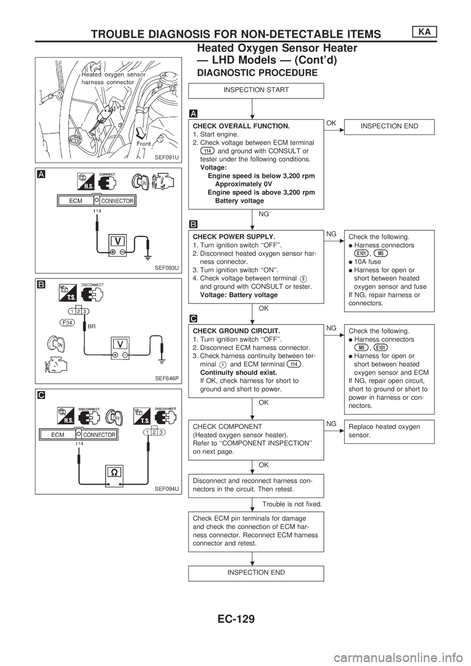
DIAGNOSTIC PROCEDURE
INSPECTION START
CHECK OVERALL FUNCTION.
1. Start engine.
2. Check voltage between ECM terminal
114and ground with CONSULT or
tester under the following conditions.
Voltage:
Engine speed is below 3,200 rpm
Approximately 0V
Engine speed is above 3,200 rpm
Battery voltage
NG
cOK
INSPECTION END
CHECK POWER SUPPLY.
1. Turn ignition switch ``OFF''.
2. Disconnect heated oxygen sensor har-
ness connector.
3. Turn ignition switch ``ON''.
4. Check voltage between terminal
V3
and ground with CONSULT or tester.
Voltage: Battery voltage
OK
cNG
Check the following.
lHarness connectorsE101,M5
l10A fuse
lHarness for open or
short between heated
oxygen sensor and fuse
If NG, repair harness or
connectors.
CHECK GROUND CIRCUIT.
1. Turn ignition switch ``OFF''.
2. Disconnect ECM harness connector.
3. Check harness continuity between ter-
minal
V1and ECM terminal114.
Continuity should exist.
If OK, check harness for short to
ground and short to power.
OK
cNG
Check the following.
lHarness connectorsM5,E101
lHarness for open or
short between heated
oxygen sensor and ECM
If NG, repair open circuit,
short to ground or short to
power in harness or con-
nectors.
CHECK COMPONENT
(Heated oxygen sensor heater).
Refer to ``COMPONENT INSPECTION''
on next page.
OK
cNG
Replace heated oxygen
sensor.
Disconnect and reconnect harness con-
nectors in the circuit. Then retest.
Trouble is not fixed.
Check ECM pin terminals for damage
and check the connection of ECM har-
ness connector. Reconnect ECM harness
connector and retest.
INSPECTION END
SEF091U
SEF093U
SEF646P
SEF094U
.
.
.
.
.
.
.
TROUBLE DIAGNOSIS FOR NON-DETECTABLE ITEMSKA
Heated Oxygen Sensor Heater
Ð LHD Models Ð (Cont'd)
EC-129
Page 299 of 1659
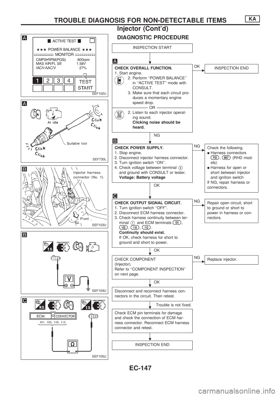
DIAGNOSTIC PROCEDURE
INSPECTION START
CHECK OVERALL FUNCTION.
1. Start engine.
2. Perform ``POWER BALANCE''
in ``ACTIVE TEST'' mode with
CONSULT.
3. Make sure that each circuit pro-
duces a momentary engine
speed drop.
----------------------------------------------------------------------------------------------------------------------------------OR----------------------------------------------------------------------------------------------------------------------------------
2. Listen to each injector operat-
ing sound.
Clicking noise should be
heard.
NG
cOK
INSPECTION END
CHECK POWER SUPPLY.
1. Stop engine.
2. Disconnect injector harness connector.
3. Turn ignition switch ``ON''.
4. Check voltage between terminal
V2
and ground with CONSULT or tester.
Voltage: Battery voltage
OK
cNG
Check the following.
lHarness connectorsF55,M47(RHD mod-
els)
lHarness for open or
short between injector
and ignition switch
If NG, repair harness or
connectors.
CHECK OUTPUT SIGNAL CIRCUIT.
1. Turn ignition switch ``OFF''.
2. Disconnect ECM harness connector.
3. Check harness continuity between ter-
minal
V1and ECM terminals101,103,110,112.
Continuity should exist.
If OK, check harness for short to
ground and short to power.
OK
cNG
Repair open circuit, short
to ground or short to
power in harness or con-
nectors.
CHECK COMPONENT
(Injector).
Refer to ``COMPONENT INSPECTION''
on next page.
OK
cNG
Replace injector.
Disconnect and reconnect harness con-
nectors in the circuit. Then retest.
Trouble is not fixed.
Check ECM pin terminals for damage
and check the connection of ECM har-
ness connector. Reconnect ECM harness
connector and retest.
INSPECTION END
SEF102U
SEF730L
SEF103U
SEF104U
SEF105U
.
.
.
.
.
.
.
TROUBLE DIAGNOSIS FOR NON-DETECTABLE ITEMSKA
Injector (Cont'd)
EC-147
Page 302 of 1659
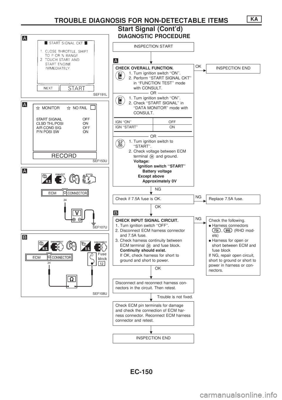
DIAGNOSTIC PROCEDURE
INSPECTION START
CHECK OVERALL FUNCTION.
1. Turn ignition switch ``ON''.
2. Perform ``START SIGNAL CKT''
in ``FUNCTION TEST'' mode
with CONSULT.
----------------------------------------------------------------------------------------------------------------------------------OR----------------------------------------------------------------------------------------------------------------------------------
1. Turn ignition switch ``ON''.
2. Check ``START SIGNAL'' in
``DATA MONITOR'' mode with
CONSULT.
----------------------------------------------------------------------------------------------------------------------------------OR----------------------------------------------------------------------------------------------------------------------------------
1. Turn ignition switch to
``START''.
2. Check voltage between ECM
terminal
V34and ground.
Voltage:
Ignition switch ``START''
Battery voltage
Except above
Approximately 0V
NG
cOK
INSPECTION END
Check if 7.5A fuse is OK.
OK
cNG
Replace 7.5A fuse.
CHECK INPUT SIGNAL CIRCUIT.
1. Turn ignition switch ``OFF''.
2. Disconnect ECM harness connector
and 7.5A fuse.
3. Check harness continuity between
ECM terminal
V34and fuse block.
Continuity should exist.
If OK, check harness for short to
ground and short to power.
OK
cNG
Check the following.
lHarness connectorsF54,M48(RHD mod-
els)
lHarness for open or
short between ECM and
fuse block
If NG, repair open circuit,
short to ground or short to
power in harness or con-
nectors.
Disconnect and reconnect harness con-
nectors in the circuit. Then retest.
Trouble is not fixed.
Check ECM pin terminals for damage
and check the connection of ECM har-
ness connector. Reconnect ECM harness
connector and retest.
INSPECTION END
IGN ``ON'' OFF
IGN ``START'' ON
SEF191L
SEF153U
SEF107U
SEF108U
.
.
.
.
.
.
TROUBLE DIAGNOSIS FOR NON-DETECTABLE ITEMSKA
Start Signal (Cont'd)
EC-150
Page 303 of 1659
Fuel Pump
SYSTEM DESCRIPTION
Camshaft position sensorcEngine speed
ECM
(ECCS
control
mod-
ule)
cFuel
pump
relay
Ignition switchcStart signal
The ECM activates the fuel pump for several sec-
onds after the ignition switch is turned on to
improve engine startability. If the ECM receives a
180É signal from the camshaft position sensor, it
knows that the engine is rotating, and causes the
pump to operate. If the 180É signal is not received
when the ignition switch is on, the engine stalls.
The ECM stops pump operation and prevents bat-
tery discharging, thereby improving safety. The
ECM does not directly drive the fuel pump. It con-
trols the ON/OFF fuel pump relay, which in turn
controls the fuel pump.Condition Fuel pump operation
Ignition switch is turned to ON.Operates for
5 seconds.
Engine running and cranking Operates.
When engine is stopped Stops in 1 second.
Except as shown above. Stops.
COMPONENT DESCRIPTION
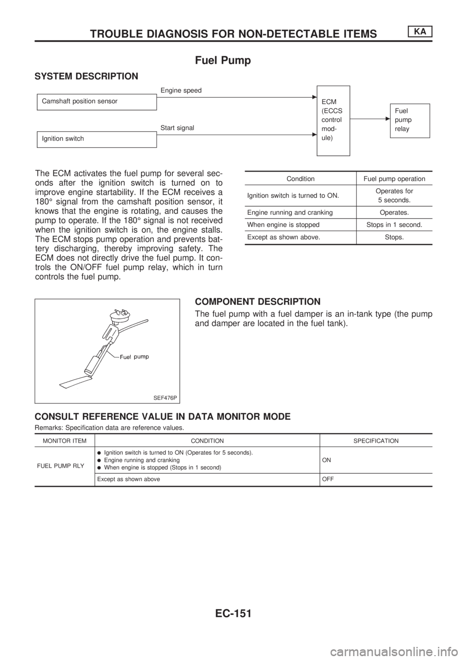
The fuel pump with a fuel damper is an in-tank type (the pump
and damper are located in the fuel tank).
CONSULT REFERENCE VALUE IN DATA MONITOR MODE
Remarks: Specification data are reference values.
MONITOR ITEM CONDITION SPECIFICATION
FUEL PUMP RLY
lIgnition switch is turned to ON (Operates for 5 seconds).lEngine running and crankinglWhen engine is stopped (Stops in 1 second)ON
Except as shown above OFF
SEF476P
TROUBLE DIAGNOSIS FOR NON-DETECTABLE ITEMSKA
EC-151
Page 308 of 1659
VA
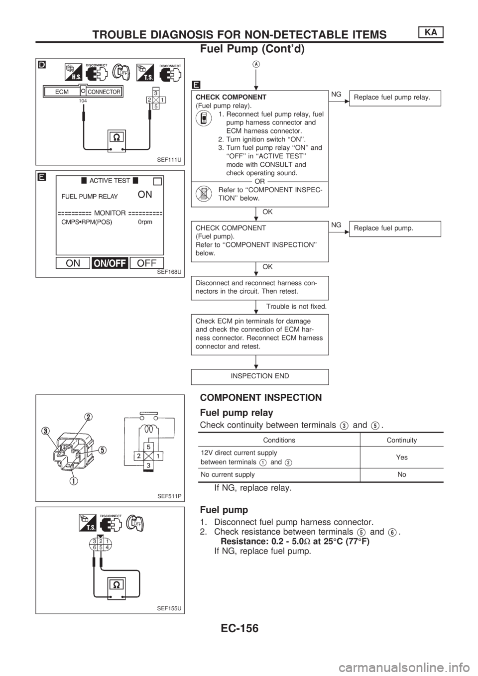
CHECK COMPONENT
(Fuel pump relay).
1. Reconnect fuel pump relay, fuel
pump harness connector and
ECM harness connector.
2. Turn ignition switch ``ON''.
3. Turn fuel pump relay ``ON'' and
``OFF'' in ``ACTIVE TEST''
mode with CONSULT and
check operating sound.
----------------------------------------------------------------------------------------------------------------------------------OR----------------------------------------------------------------------------------------------------------------------------------
Refer to ``COMPONENT INSPEC-
TION'' below.
OK
cNG
Replace fuel pump relay.
CHECK COMPONENT
(Fuel pump).
Refer to ``COMPONENT INSPECTION''
below.
OK
cNG
Replace fuel pump.
Disconnect and reconnect harness con-
nectors in the circuit. Then retest.
Trouble is not fixed.
Check ECM pin terminals for damage
and check the connection of ECM har-
ness connector. Reconnect ECM harness
connector and retest.
INSPECTION END
COMPONENT INSPECTION
Fuel pump relay
Check continuity between terminalsV3andV5.
Conditions Continuity
12V direct current supply
between terminals
V1andV2Yes
No current supply No
If NG, replace relay.
Fuel pump
1. Disconnect fuel pump harness connector.
2. Check resistance between terminals
V5andV6.
Resistance: 0.2 - 5.0Wat 25ÉC (77ÉF)
If NG, replace fuel pump.
SEF111U
SEF168U
SEF511P
SEF155U
.
.
.
.
.
TROUBLE DIAGNOSIS FOR NON-DETECTABLE ITEMSKA
Fuel Pump (Cont'd)
EC-156
Page 486 of 1659
Unified Control Meter System Description
UNIFIED CONTROL METER
Speedometer, odo/trip meter, tachometer, fuel gauge and water
temperature gauge are controlled totally by control unit combined
with speedometer.
Meter/gauge Operation and Odo/Trip Meter
Segment Check in Diagnosis Mode
DIAGNOSIS FUNCTION
lOdo/trip meter segment can be checked in diagnosis mode.
lMeters/gauges can be checked in diagnosis mode.
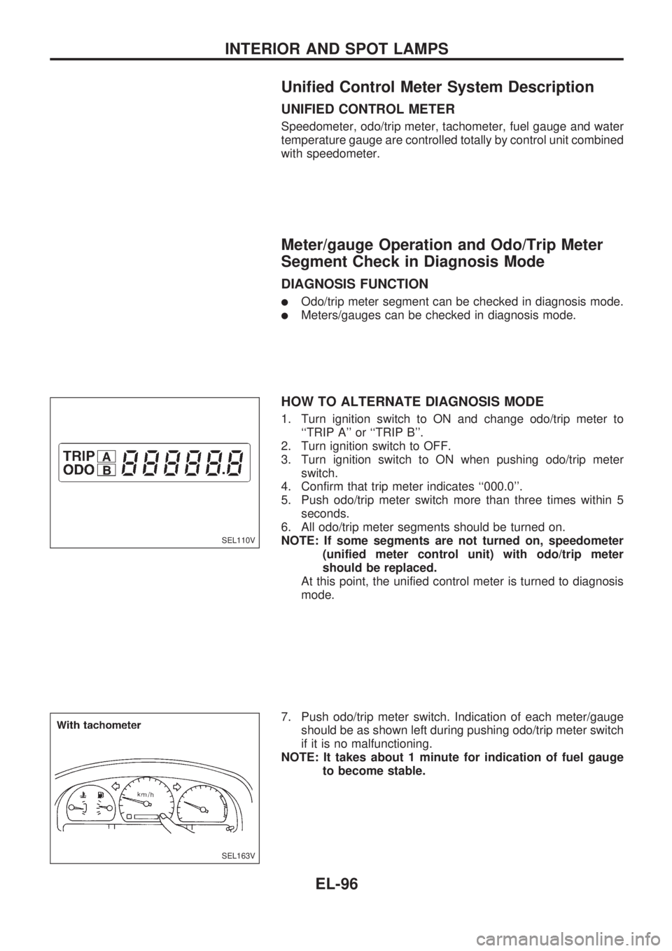
HOW TO ALTERNATE DIAGNOSIS MODE
1. Turn ignition switch to ON and change odo/trip meter to
``TRIP A'' or ``TRIP B''.
2. Turn ignition switch to OFF.
3. Turn ignition switch to ON when pushing odo/trip meter
switch.
4. Confirm that trip meter indicates ``000.0''.
5. Push odo/trip meter switch more than three times within 5
seconds.
6. All odo/trip meter segments should be turned on.
NOTE: If some segments are not turned on, speedometer
(unified meter control unit) with odo/trip meter
should be replaced.
At this point, the unified control meter is turned to diagnosis
mode.
7. Push odo/trip meter switch. Indication of each meter/gauge
should be as shown left during pushing odo/trip meter switch
if it is no malfunctioning.
NOTE: It takes about 1 minute for indication of fuel gauge
to become stable.
SEL110V
SEL163V
INTERIOR AND SPOT LAMPS
EL-96
Page 488 of 1659
Trouble Diagnoses
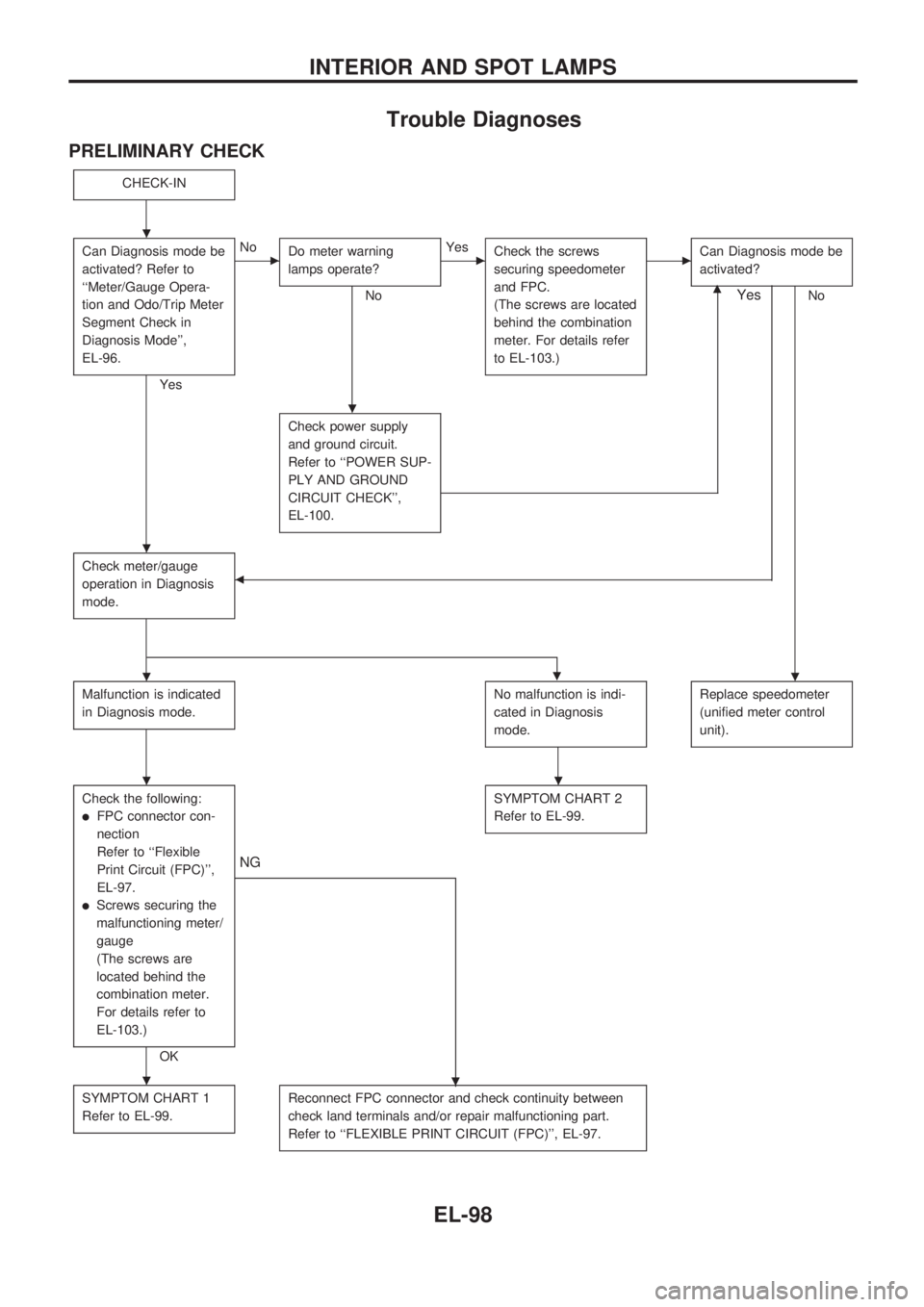
PRELIMINARY CHECK
CHECK-IN
Can Diagnosis mode be
activated? Refer to
``Meter/Gauge Opera-
tion and Odo/Trip Meter
Segment Check in
Diagnosis Mode'',
EL-96.
Yes
cNo
Do meter warning
lamps operate?
No
cYes
Check the screws
securing speedometer
and FPC.
(The screws are located
behind the combination
meter. For details refer
to EL-103.)cCan Diagnosis mode be
activated?
Nom
Check power supply
and ground circuit.
Refer to ``POWER SUP-
PLY AND GROUND
CIRCUIT CHECK'',
EL-100.
Check meter/gauge
operation in Diagnosis
mode.b
Yes
.
Malfunction is indicated
in Diagnosis mode.No malfunction is indi-
cated in Diagnosis
mode.Replace speedometer
(unified meter control
unit).
Check the following:
lFPC connector con-
nection
Refer to ``Flexible
Print Circuit (FPC)'',
EL-97.
lScrews securing the
malfunctioning meter/
gauge
(The screws are
located behind the
combination meter.
For details refer to
EL-103.)
OK
.
NG
SYMPTOM CHART 2
Refer to EL-99.
SYMPTOM CHART 1
Refer to EL-99.Reconnect FPC connector and check continuity between
check land terminals and/or repair malfunctioning part.
Refer to ``FLEXIBLE PRINT CIRCUIT (FPC)'', EL-97.
.
.
.
..
..
.
INTERIOR AND SPOT LAMPS
EL-98
Page 510 of 1659
System Description
WIPER OPERATION
The wiper switch is controlled by a lever built into the combination switch.
There are two or three wiper switch positions:
lLO speed
lHI speed
lINT (Intermittent wiper models only)
With the ignition switch in the ACC or ON position, power is supplied
lthrough 20A fuse (No.16, located in the fuse block)
lto wiper motor terminalV4.
Low and high speed wiper operation
Ground is supplied to wiper switch terminal
V17through body groundsM1andM54.
When the wiper switch is placed in the LO position, ground is supplied
lthrough terminalV14of the wiper switch
lto wiper motor terminalV2.
With power and ground supplied, the wiper motor operates at low speed.
When the wiper switch is placed in the HI position, ground is supplied
lthrough terminalV16of the wiper switch
lto wiper motor terminalV3.
With power and ground supplied, the wiper motor operates at high speed.
Auto stop operation
With wiper switch turned OFF, wiper motor will continue to operate until wiper arms reach windshield base.
When wiper arms are not located at base of windshield with wiper switch OFF, ground is provided
lfrom terminalV14of the wiper switch
lto wiper motor terminalV2, in order to continue wiper motor operation at low speed.
Ground is also supplied
lthrough terminalV13of the wiper switch
lto wiper amplifier terminalV2(Intermittent wiper models only)
lthrough terminalV7of the wiper amplifier (Intermittent wiper models only)
lto wiper motor terminalV5
lthrough terminalV6of the wiper motor, and
lthrough body groundsM1andM54.
When wiper arms reach base of windshield, wiper motor terminals
V4andV5are connected instead of ter-
minals
V5andV6. Wiper motor will then stop wiper arms at the PARK position.
Intermittent operation
The wiper motor operates the wiper arms one time at low speed at an interval of approximately 7 seconds.
This feature is controlled by the wiper amplifier.
When the wiper switch is placed in the INT position, ground is supplied
lto wiper amplifier terminalV1
lfrom wiper switch terminalV15
lthrough body groundsM1andM54.
lto wiper motor terminalV2
lthrough the wiper switch terminalV14
lto wiper switch terminalV13
lthrough wiper amplifier terminalV2
lto wiper amplifier terminalV3
lthrough body groundsM1andM54.
With power and ground supplied, the wiper motor operates at low speed intermittently.
FRONT WIPER AND WASHER
EL-120