Page 82 of 1659
General Specifications
2WD MODELS
Applied model Without ABS With ABS
Front brake
CL28VD disc brake
Type
Cylinder bore diameter mm (in) 42.8 (1.685) x 2
Pad dimension mm (in)
Length x width x thickness146.6 x 48.5 x 10.0
(5.77 x 1.909 x 0.394)
Rotor outer diameter x thickness
mm (in)260x26
(10.24 x 1.02)
Rear brake
TypeLT26B drum brake
Wheel cylinder bore diameter
mm (in)23.81 (15/16)
Lining dimension mm (in)
Length x width x thickness249.6 x 50 x 5.5
(9.83 x 1.97 x 0.217)
Drum inner diameter mm (in) 260 (10.24)
Master cylinder bore diameter
mm (in)23.81 (15/16) 25.4 (1)
Control valve
TypeLSV
Split point x reducing ratio
kPa (bar, kg/cm
2, psi)(Variable) x 0.15
Brake booster
ModelM195T
Diaphragm diameter mm (in)Primary: 205 (8.07)
Secondary: 180 (7.09)
Recommended brake fluid DOT 3 or DOT 4*1
*1: Refer to MA section (``Fluids and Lubricants'', ``RECOMMENDED FLUIDS AND LUBRICANTS'').
SERVICE DATA AND SPECIFICATIONS (SDS)
BR-78
Page 83 of 1659
4WD MODELS
Applied modelAll
Front brake
TypeCL28VD disc brake
Cylinder bore diameter mm (in) 42.8 (1.685) x 2
Pad dimension mm (in)
Length x width x thickness146.6 x 48.5 x 10
(5.77 x 1.909 x 0.39)
Rotor outer diameter x thickness
mm (in)277 x 26 (10.91 x 1.02)
Rear brake
TypeLT30A drum brake
Wheel cylinder bore diameter
mm (in)22.22 (7/8)
Lining dimension mm (in)
Length x width x thickness296.0 x 50.0 x 6.1 (11.65 x 1.969 x 0.240)
Drum inner diameter mm (in) 295 (11.61)
Master cylinder bore diameter
mm (in)23.81 (15/16)
Control valve
TypeLSV
Split point x reducing ratio
kPa (bar, kg/cm
2, psi)(Variable) x 0.15
Brake booster
ModelM215T
Diaphragm diameter mm (in)Primary: 230 (9.06)
Secondary: 205 (8.07)
Recommended brake fluid DOT 3 or DOT 4*1
*1: Refer to MA section (``Fluids and Lubricants'', ``RECOMMENDED FLUIDS AND LUBRICANTS'').
SERVICE DATA AND SPECIFICATIONS (SDS)
General Specifications (Cont'd)
BR-79
Page 90 of 1659
Adjusting Clutch Pedal
1. Adjust pedal height with pedal stopper.
2. Adjust pedal free play with push rod.
Air Bleeding Procedure
Bleed air according to the following procedure.
Bleed the air from the master cylinder (RHD models only)
and then the operating cylinder.
1. Fill the master cylinder reservoir tank with new brake fluid.
2. Connect a transparent vinyl hose to the air bleeder.
3. Slowly depress the clutch pedal to its full stroke length and
release it completely. Repeat this operation several times at
2 to 3 second intervals.
4. Open the air bleeder with the clutch pedal fully depressed.
5. Close the air bleeder.
6. Release the clutch pedal and wait at least 5 seconds.
7. Repeat steps 3 through 6 above until air bubbles no longer
appear in the brake fluid.
SCL742-A
.LHD model
221 - 231 mm (8.70 - 0.09 in)
RHD model
195 - 205 mm (7.68 - 8.07 in)
Pedal free play ``A'':
1 - 1.5 mm (0.039 - 0.059 in)
SCL203
INSPECTION AND ADJUSTMENT
CL-5
Page 96 of 1659
WATERPROOF Ð for 4WD model
lApply recommended sealant to contact surface of transmis-
sion case dust cover and withdrawal lever, then install dust
cover clip.
Recommended sealant:
Nissan genuine part KP115-00100, Three Bond TB
1212 or equivalent.
SCL760
SCL761
CLUTCH RELEASE MECHANISM
CL-11
Page 174 of 1659

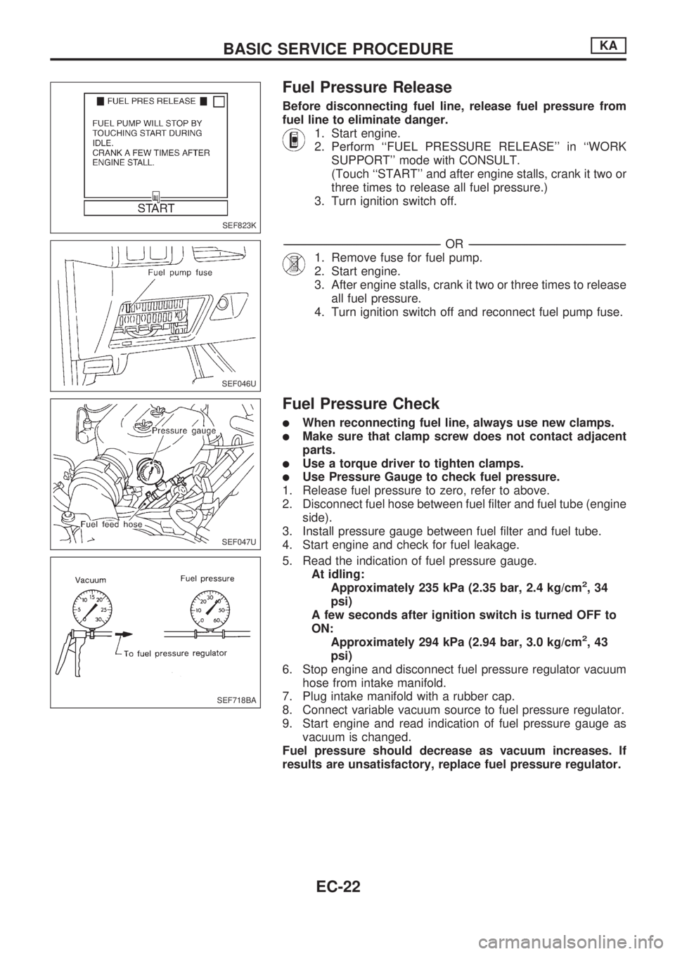
Fuel Pressure Release
Before disconnecting fuel line, release fuel pressure from
fuel line to eliminate danger.
1. Start engine.
2. Perform ``FUEL PRESSURE RELEASE'' in ``WORK
SUPPORT'' mode with CONSULT.
(Touch ``START'' and after engine stalls, crank it two or
three times to release all fuel pressure.)
3. Turn ignition switch off.
-------------------------------------------------------------------------------------------------------------------------------------------------------------------------------------------------------------------------------------------------OR-------------------------------------------------------------------------------------------------------------------------------------------------------------------------------------------------------------------------------------------------
1. Remove fuse for fuel pump.
2. Start engine.
3. After engine stalls, crank it two or three times to release
all fuel pressure.
4. Turn ignition switch off and reconnect fuel pump fuse.
Fuel Pressure Check
lWhen reconnecting fuel line, always use new clamps.
lMake sure that clamp screw does not contact adjacent
parts.
lUse a torque driver to tighten clamps.
lUse Pressure Gauge to check fuel pressure.
1. Release fuel pressure to zero, refer to above.
2. Disconnect fuel hose between fuel filter and fuel tube (engine
side).
3. Install pressure gauge between fuel filter and fuel tube.
4. Start engine and check for fuel leakage.
5. Read the indication of fuel pressure gauge.
At idling:
Approximately 235 kPa (2.35 bar, 2.4 kg/cm
2,34
psi)
A few seconds after ignition switch is turned OFF to
ON:
Approximately 294 kPa (2.94 bar, 3.0 kg/cm
2,43
psi)
6. Stop engine and disconnect fuel pressure regulator vacuum
hose from intake manifold.
7. Plug intake manifold with a rubber cap.
8. Connect variable vacuum source to fuel pressure regulator.
9. Start engine and read indication of fuel pressure gauge as
vacuum is changed.
Fuel pressure should decrease as vacuum increases. If
results are unsatisfactory, replace fuel pressure regulator.
SEF823K
SEF046U
SEF047U
SEF718BA
BASIC SERVICE PROCEDUREKA
EC-22
Page 180 of 1659

VC
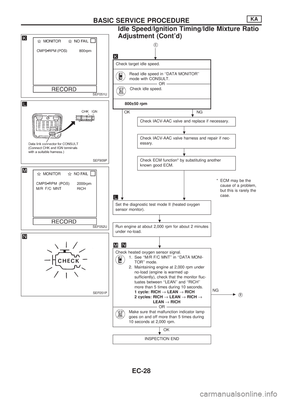
Check target idle speed.
-------------------------------------------------------------------------------------------------------------------------------------------------------------------------------------------------------------------------------------------------------------------------------------------------------------------------------------------------------------------------
Read idle speed in ``DATA MONITOR''
mode with CONSULT.
-----------------------------------------------------------------------------------------------------------------------------------------------------------------OR -----------------------------------------------------------------------------------------------------------------------------------------------------------------
Check idle speed.
-------------------------------------------------------------------------------------------------------------------------------------------------------------------------------------------------------------------------------------------------------------------------------------------------------------------------------------------------------------------------
800 50 rpm
OKNG
Check IACV-AAC valve and replace if necessary.
Check IACV-AAC valve harness and repair if nec-
essary.
Check ECM function* by substituting another
known good ECM.
* ECM may be the
cause of a problem,
but this is rarely the
case.
.
Set the diagnostic test mode II (heated oxygen
sensor monitor).
Run engine at about 2,000 rpm for about 2 minutes
under no-load.
Check heated oxygen sensor signal.
1. See ``M/R F/C MNT'' in ``DATA MONI-
TOR'' mode.
2. Maintaining engine at 2,000 rpm under
no-load (engine is warmed up
sufficiently), check that the monitor fluc-
tuates between ``LEAN'' and ``RICH''
more than 5 times during 10 seconds.
1 cycle: RICH®LEAN®RICH
2 cycles: RICH®LEAN®RICH®
LEAN®RICH
-----------------------------------------------------------------------------------------------------------------------------------------------------------------OR -----------------------------------------------------------------------------------------------------------------------------------------------------------------
Make sure that malfunction indicator lamp
goes on and off more than 5 times during
10 seconds at 2,000 rpm.
OK
cNG
VD
INSPECTION END
SEF051U
SEF909P
SEF052U
SEF051P
.
.
.
.
.
.
.
.
BASIC SERVICE PROCEDUREKA
Idle Speed/Ignition Timing/Idle Mixture Ratio
Adjustment (Cont'd)
EC-28
Page 188 of 1659

Introduction
The ECM (ECCS control module) has an on board diagnostic system, which detects malfunctions related to
engine sensors or actuators. Self-diagnosis items are listed in ``DIAGNOSTIC TROUBLE CODE INDEX'',
EC-1.
The malfunction indicator lamp (MIL) on the instrument panel lights up when a malfunction is detected, or
when the ECM enters fail-safe mode (Refer to EC-61).
Diagnostic Trouble Code (DTC)
HOW TO CONFIRM MALFUNCTION ITEMS
Malfunction items can be confirmed by the following methods.
1. The number of blinks of the malfunction indicator lamp in the Diagnostic Test Mode II (Self- Diag-
nostic Results) indicates the DTC. Examples: 11, 21 etc.
2. CONSULT displays the malfunctioning component or system in ``SELF DIAGNOSTIC RESULTS''
mode.
lOutput of a DTC indicates a malfunction. However, Mode II does not indicate whether the mal-
function is still occurring or has occurred in the past and has returned to normal.
CONSULT can identify malfunction status as shown below. Therefore, using CONSULT (if avail-
able) is recommended.
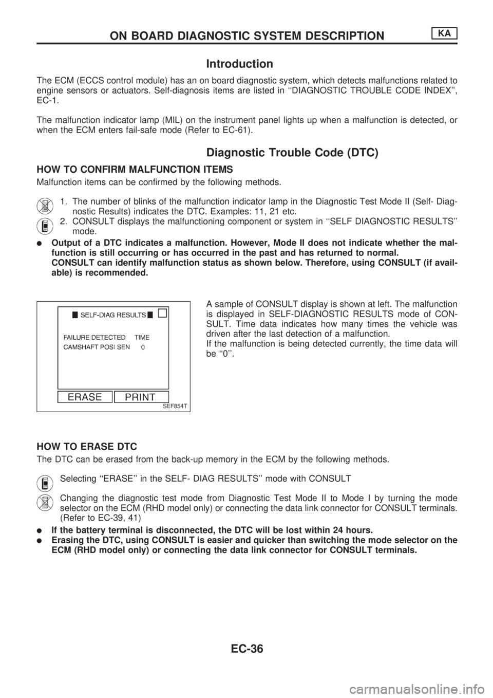
A sample of CONSULT display is shown at left. The malfunction
is displayed in SELF-DIAGNOSTIC RESULTS mode of CON-
SULT. Time data indicates how many times the vehicle was
driven after the last detection of a malfunction.
If the malfunction is being detected currently, the time data will
be ``0''.
HOW TO ERASE DTC
The DTC can be erased from the back-up memory in the ECM by the following methods.
Selecting ``ERASE'' in the SELF- DIAG RESULTS'' mode with CONSULT
Changing the diagnostic test mode from Diagnostic Test Mode II to Mode I by turning the mode
selector on the ECM (RHD model only) or connecting the data link connector for CONSULT terminals.
(Refer to EC-39, 41)
lIf the battery terminal is disconnected, the DTC will be lost within 24 hours.
lErasing the DTC, using CONSULT is easier and quicker than switching the mode selector on the
ECM (RHD model only) or connecting the data link connector for CONSULT terminals.
SEF854T
ON BOARD DIAGNOSTIC SYSTEM DESCRIPTIONKA
EC-36
Page 189 of 1659
How to erase DTC (With CONSULT)
1. If the ignition switch stays ``ON'' after repair work, be sure to turn ignition switch ``OFF'' once. Wait at
least 5 seconds and then turn it ``ON'' (engine stopped) again.
2. Turn CONSULT ``ON'' and touch ``ENGINE''.
3. Touch ``SELF-DIAG RESULTS''.
4. Touch ``ERASE''. (The DTC in the ECM will be erased.)
How to erase DTC (Without CONSULT)
1. If the ignition switch stays ``ON'' after repair work, be sure to turn ignition switch ``OFF'' once. Wait at
least 5 seconds and then turn it ``ON'' again.
2. Change the diagnostic test mode from Mode II to Mode I by turning the mode selector on the ECM (RHD
model only) or connecting the data link connector for CONSULT terminals. (See EC-39, 41)
SEF054U
ON BOARD DIAGNOSTIC SYSTEM DESCRIPTIONKA
Diagnostic Trouble Code (DTC) (Cont'd)
EC-37