1998 NISSAN PICK-UP belt
[x] Cancel search: beltPage 865 of 1659
Combination lamp, front, removal and
installation................................................... BT-5
Combination lamp, rear, removal and
installation................................................. BT-24
Combination meter removal and instal-
lation - See Instrument panel ................... BT-12
Combination switch ...................................... EL-42
Combustion chamber replacement ............. EM-59
Compression pressure (KA24 engine) ........ EM-10
Compression pressure (TD25 engine) ........ EM-51
Compressor clutch removal and
installation ................................................ HA-60
Compressor precaution ................................. HA-6
Compressor special service tool ................... HA-6
Connecting rod (KA24 engine).................... EM-40
Connecting rod (TD25 engine).................... EM-77
Connecting rod bearing clearance
(KA24 engine).......................................... EM-44
Connecting rod bearing clearance
(TD25 engine).......................................... EM-77
Connecting rod bushing clearance
(KA24 engine).......................................... EM-45
Connecting rod bushing clearance
(TD25 engine).......................................... EM-78
Connector inspection .................................... GI-18
Control lever (M/T) ...................................... MT-17
Control lever (Transfer) .................................. TF-7
Control units (terminal arrangement) ..........Foldout
Coolant mixture ratio ................................... MA-14
Coolant replacement (KA24 engine) ........... MA-16
Coolant replacement (TD25 engine) ........... MA-25
Cooling circuit (engine)
(KA24 engine) ............................................ LC-6
Cooling circuit (engine)
(TD25 engine) .......................................... LC-19
Cooling fan (KA24 engine)........................... LC-10
Cooling fan (TD25 engine) .................... LC-21, 26
Cooling fan control system .......................... LC-25
Counter gear (M/T) (FS5R30A)................... MT-36
Counter gear (M/T) (FS5W71C).................. MT-15
Counter gear (Transfer) ................................. TF-9
Coupling sleeve (M/T) (FS5R30A) .............. MT-36
Coupling sleeve (M/T) (FS5W71C) ............. MT-15
Crank angle sensor built into distribu-
tor - See Camshaft position sensor ......... EC-82
Crankcase emission control system -
See Positive crankcase ventilation .......... EC-21
Crankcase ventilation system - See
Positive crankcase ventilation.................. EC-21
Crankshaft (KA24 engine) ........................... EM-42
Crankshaft (TD25 engine) ........................... EM-79
Crankshaft position sensor (POS) ............... EC-82
Crankshaft position sensor (REF) ............... EC-82
Cylinder block (KA24 engine) ..................... EM-38
Cylinder block (TD25 engine) ..................... EM-74
Cylinder block boring................................... EM-41
Cylinder head (KA24 engine) ...................... EM-24
Cylinder head (TD25 engine) ...................... EM-53
Cylinder head bolt tightening ...................... EM-64
Cylinder head gasket selection ................... EM-63Cylinder liner ............................................... EM-74
D
D/LOCK - Wiring diagram ...........................EL-167
DEF - Wiring diagram ................................ EL-135
DTRL - Wiring diagram ................................ EL-54
Data link connector for Consult ................... EC-45
Daytime light system .................................... EL-51
Defroster door control rod adjustment......... HA-45
Diagnosis sensor unit .................................. RS-10
Diagnostic trouble code (DTC) for
ECCS OBD system.................................. EC-36
Differential carrier assembly (C200) ............ PD-51
Differential carrier assembly (H233B) ......... PD-72
Differential carrier assembly (R180A) ......... PD-27
Differential carrier disassembly
(C200) ...................................................... PD-34
Differential carrier disassembly
(H233B) .................................................... PD-57
Differential gear oil replacement ................. MA-34
Dim-dip lamp system.................................... EL-58
Dimensions ................................................... GI-44
Distributor ignition (DI) system .................... EC-17
Dome light - See Interior lamp ..................... EL-85
Door glass .................................................... BT-10
Door lock ...................................................... BT-10
Door mirror ................................................... BT-39
Door trim ...................................................... BT-18
Door, front .................................................... BT-10
Door, rear ..................................................... BT-11
Drive belt inspection (KA24 engine) ........... MA-15
Drive belt inspection (TD25 engine) ........... MA-23
Drive chain (Transfer) .................................... TF-9
Drive pinion diff. inspection (C200) ............. PD-38
Drive pinion diff. inspection (H233B) ........... PD-60
Drive pinion height (C200)........................... PD-47
Drive pinion height (H233B) ........................ PD-67
Drive pinion height (R180A) ........................ PD-24
Drive shaft (front) ......................................... FA-21
E
ECCS basic inspection .................................EC-58
ECCS circuit diagram .................................... EC-8
ECCS component parts location ................. EC-10
ECCS fail-safe chart .................................... EC-61
ECCS on board diagnostic system ............. EC-36
ECCS relay .................................................. EC-75
ECCS symptom matrix chart ....................... EC-62
ECCS system diagram .................................. EC-9
ECTS - Wiring diagram ............................... EC-96
EGR control (EGRC) - solenoid valve....... EC-218
EGR control valve...................................... EC-218
EGRC - Wiring diagram............................. EC-213
EVAP canister.............................................. EC-19
EVAP canister purge control solenoid
valve ....................................................... EC-140
ALPHABETICAL INDEX
IDX-3
Page 866 of 1659

EVAP vapor lines inspection ....................... MA-22
Electrical diagnoses ...................................... GI-21
Engine compartment .................................... BT-44
Engine control module (ECM) ....................... EC-5
Engine coolant temperature sensor
(ECTS) (KA24 engine) ............................. EC-95
Engine coolant temperature sensor
(ECTS) (TD25 engine) ........................... EC-209
Engine oil filter replacement
(KA24 engine).......................................... MA-20
Engine oil filter replacement
(TD25 engine).......................................... MA-24
Engine oil precautions .................................... GI-4
Engine oil replacement
(KA24 engine).......................................... MA-19
Engine oil replacement
(TD25 engine).......................................... MA-24
Engine outer component parts
(KA24 engine)............................................ EM-9
Engine outer component parts
(TD25 engine).......................................... EM-49
Engine removal (KA24 engine) ................... EM-36
Engine removal (TD25 engine) ................... EM-69
Engine room - See Engine
compartment............................................. BT-44
Engine speed sensor ................................. EC-219
Evaporative emission (EVAP) system ......... EC-19
Exhaust system inspection.......................... MA-32
Exhaust system .............................................. FE-5
Exterior ......................................................... BT-24
F
F/PUMP - Wiring diagram...........................EC-153
FCUT - Wiring diagram ............................. EC-225
FICD - Wiring diagram (KA24 engine) ...... EC-168
FICD - Wiring diagram (TD25 engine) ...... EC-230
Fan switch.................................................... HA-43
Fast idle cam (FIC) inspection and
adjustment................................................ EC-24
Final drive disassembly (C200) ................... PD-34
Final drive disassembly (H233B)................. PD-56
Final drive pre-inspection (C200) ................ PD-34
Final drive pre-inspection (H233B) .............. PD-56
Final drive removal and installation ............. PD-15
Floor trim ...................................................... BT-15
Flow charts.................................................... GI-31
Fluids ........................................................... MA-12
Flywheel (clutch) .......................................... CL-12
Flywheel runout (KA24 engine)................... EM-45
Flywheel runout (TD25 engine)................... EM-80
Fog lamp, rear .............................................. EL-72
Fork rod (M/T) (FS5R30A) .......................... MT-38
Fork rod (M/T) (FS5W71C) ......................... MT-17
Front axle ..................................................... FA-12
Front bumper.................................................. BT-5
Front case (Transfer) ..................................... TF-8
Front combination lamp removal and
installation................................................... BT-5Front disc brake ........................................... BR-21
Front door..................................................... BT-10
Front drive shaft (Transfer) ............................ TF-9
Front final drive disassembly (4WD) ........... PD-17
Front final drive pre-inspection (4WD) ........ PD-17
Front final drive removal and installa-
tion (4WD) ................................................ PD-14
Front seat belt................................................ RS-3
Front seat ..................................................... BT-30
Front suspension.......................................... FA-26
Front washer .............................................. EL-120
Front wiper ................................................. EL-120
Fuel check valve .......................................... EC-20
Fuel cut control (at no load & high
engine speed) (KA24 engine) .................. EC-18
Fuel cut control (at no load & high
engine speed) ........................................ EC-225
Fuel filter replacement (KA24 engine) ........ MA-18
Fuel filter replacement (TD25 engine) ........ MA-27
Fuel injector ............................................... EC-144
Fuel line inspection (KA24 engine) ............. MA-18
Fuel line inspection (TD25 engine) ............. MA-28
Fuel precautions ............................................. GI-5
Fuel pressure check .................................... EC-22
Fuel pressure release .................................. EC-22
Fuel pump .................................................. EC-151
Fuel pump relay ......................................... EC-156
Fuel system .................................................... FE-3
Fuel tank vacuum relief valve...................... EC-20
Fuse block.................................................. Foldout
Fuse.............................................................. EL-13
Fusible link ................................................... EL-13G
GLOW - Wiring diagram .............................EC-197
Garage jack and safety stand....................... GI-49
Gear components (M/T) (FS5R30A) ........... MT-36
Gear components (M/T) (FS5W71C) .......... MT-15
Glass ............................................................ BT-10
Glow plug ................................................... EC-208
Glow relay .................................................. EC-208
Grease ......................................................... MA-12
Ground clearance ......................................... GI-44
Ground distribution ....................................... EL-14
H
H/AIM - Wiring diagram .................................EL-64
H/LAMP - Wiring diagram ............................ EL-44
H02S - Wiring diagram .............................. EC-124
HFC134a (R134a) system precaution ........... HA-2
HFC134a (R134a) system service
procedure ................................................. HA-48
HFC134a (R134a) system service
tools............................................................ HA-8
HFC134a system service equipment
precaution ................................................ HA-10
ALPHABETICAL INDEX
IDX-4
Page 869 of 1659
Radiator (KA24 engine) ................................. LC-9
Radiator (TD25 engine) ............................... LC-24
Rear axle ....................................................... RA-5
Rear body..................................................... BT-40
Rear case (Transfer) ...................................... TF-8
Rear combination lamp removal and
installation................................................. BT-24
Rear cover gasket replacement diff. ........... PD-13
Rear door ..................................................... BT-11
Rear drum brake.......................................... BR-26
Rear fog lamp............................................... EL-72
Rear seat belt ................................................ RS-4
Rear seat...................................................... BT-33
Rear suspension .......................................... RA-12
Rear window defogger ............................... EL-135
Refrigerant connection precaution................. HA-2
Refrigerant discharging evacuating
charging ................................................... HA-49
Refrigerant general precaution ...................... HA-2
Refrigerant lines........................................... HA-52
Refrigeration cycle ....................................... HA-12
Release bearing (clutch) ................................ CL-9
Removal and installation (Transfer) ............... TF-6
Resistor ...................................................... EC-105
Reverse idler shaft (M/T) (FS5R30A) ......... MT-36
Reverse idler shaft (M/T) (FS5W71C) ........ MT-15
Reverse lamp switch (M/T) - See
Back-up lamp switch (M/T) ........................ MT-9
Reverse main gear (M/T) (FS5R30A) ......... MT-36
Reverse main gear (M/T) (FS5W71C) ........ MT-15
Ring gear diff. inspection (C200)................. PD-38
Ring gear diff. inspection (H233B) .............. PD-60
Road wheel size ........................................... GI-46
Roof trim....................................................... BT-21
Room lamp - See Interior lamp.................... EL-85
Rotor disc (front) .......................................... FA-16
S
S/SIG - Wiring diagram...............................EC-149
SAE J1930 terminology list........................... GI-55
SMJ (super multiple junction) .................... Foldout
SRS - See Supplemental Restraint
System ....................................................... RS-6
SRS Trouble diagnoses
(2WD models) .......................................... RS-17
SRS Trouble diagnoses
(4WD models) .......................................... RS-22
START - Wiring diagram .............................. EL-26
SWL/V - Wiring diagram ............................ EC-163
Screw jack..................................................... GI-48
Seal - See Exterior....................................... BT-24
Seat belt inspection ..................................... MA-40
Seat belt, front ............................................... RS-3
Seat belt, rear ................................................ RS-4
Seat, front..................................................... BT-30
Seat, rear ..................................................... BT-33
Self-diagnostic results.................................. EC-38
Shift control (Transfer) ................................. TF-10Shift control components (M/T)
(FS5R30A) ................................................MT-38
Shift control components (M/T)
(FS5W71C) .............................................. MT-17
Shift fork (M/T) (FS5R30A) ......................... MT-38
Shift fork (M/T) (FS5W71C) ........................ MT-17
Shift lever (FS5R30A) ................................. MT-38
Shift lever (FS5W71C) ................................ MT-17
Shock absorber (front) ................................. FA-28
Shock absorber (rear).................................. RA-13
Side bearing preload (R180A) ..................... PD-23
Side bearing preload (C200) ....................... PD-45
Side trim ....................................................... BT-15
Side window ................................................. BT-38
Spark plug replacement .............................. MA-20
Spiral cable .................................................. RS-11
Spot lamp ..................................................... EL-85
Stabilizer bar (front) ..................................... FA-31
Standardized relay ......................................... EL-3
Start signal ................................................. EC-149
Starter ........................................................... EL-33
Starting system............................................. EL-26
Steering gear and linkage inspection.......... MA-37
Steering gear oil level ................................. MA-38
Steering knuckle........................................... FA-18
Steering linkage ........................................... ST-37
Steering wheel and column ........................... ST-9
Steering wheel play........................................ ST-6
Steering wheel turning force .......................... ST-6
Striking rod (M/T) (FS5R30A) ..................... MT-38
Striking rod (M/T) (FS5W71C) .................... MT-17
Sub-gear (M/T) (FS5R30A) ......................... MT-36
Sub-gear (M/T) (FS5W71C) ........................ MT-15
Sunroof ......................................................... BT-35
Supplemental Restraint System .................... RS-6
Supplemental restraint system - Wiring
diagram (2WD models) ............................ RS-18
Supplemental restraint system - Wiring
diagram (4WD models) ............................ RS-26
Swirl control valve control solenoid
valve ....................................................... EC-161
Symbols and abbreviations............................. GI-8
Synchronizer (M/T) (FS5R30A) ................... MT-36
Synchronizer (M/T) (FS5W71C) .................. MT-15
T
TAIL/L - Wiring diagram ................................EL-66
TPS - Wiring diagram ................................ EC-115
TURN - Wiring diagram................................ EL-75
Tail lamp ....................................................... EL-66
Temperature control cable and linkage
adjustment................................................ HA-47
Tension rod (front) ....................................... FA-33
Thermal protector ........................................ HA-45
Thermo control amp .................................... HA-44
Thermostat (KA24 engine) ............................. LC-8
Thermostat (TD25 engine) ........................... LC-23
Three way catalyst precautions ...................... GI-4
ALPHABETICAL INDEX
IDX-7
Page 872 of 1659
Supplemental Restraint System (SRS) ``AIR
BAG'' (4WD models)
The Supplemental Restraint System ``AIR BAG'', used along with a seat belt, helps to reduce the risk or
severity of injury to the driver in a frontal collision. The Supplemental Restraint System consists of air bag
module (located in the center of the steering wheel), diagnosis sensor unit, warning lamp, wiring harness
and spiral cable. Information necessary to service the system safely is included in theRS sectionof this
Service Manual.
WARNING:
lTo avoid rendering the SRS inoperative, which could increase the risk of personal injury or death
in the event of a collision which would result in air bag inflation, all maintenance must be per-
formed by an authorized NISSAN dealer.
lImproper maintenance, including incorrect removal and installation of the SRS, can lead to per-
sonal injury caused by unintentional activation of the system.
lDo not use electrical test equipment on any circuit related to the SRS unless instructed to in this
Service Manual. SRS wiring harnesses are covered with yellow insulation either just before the
harness connectors or for the complete harness, for easy identification.
Supplemental Restraint System (SRS) ``AIR
BAG'' (2WD models)
The Supplemental Restraint System ``AIR BAG'', used along with a seat belt, helps to reduce the risk or
severity of injury to the driver in a frontal collision. The Supplemental Restraint System consists of air bag
module (located in the center of the steering wheel), diagnosis sensor unit, warning lamp and spiral cable.
Information necessary to service the system safely is included in theRS sectionof this Service Manual.
WARNING:
lTo avoid rendering the SRS inoperative, which could increase the risk of personal injury or death
in the event of a collision which would result in air bag inflation, all maintenance must be per-
formed by an authorized NISSAN dealer.
lImproper maintenance, including incorrect removal and installation of the SRS, can lead to per-
sonal injury caused by unintentional activation of the system.
lDo not use electrical test equipment on any circuit related to the SRS.
PRECAUTIONS AND PREPARATION
HA-1
Page 892 of 1659
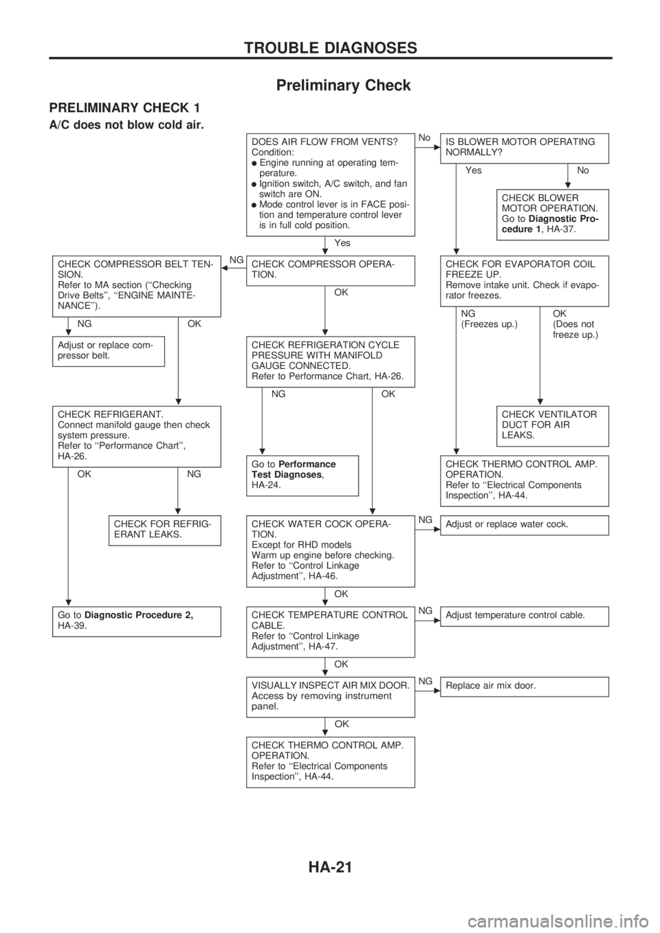
Preliminary Check
PRELIMINARY CHECK 1
A/C does not blow cold air.
DOES AIR FLOW FROM VENTS?
Condition:
lEngine running at operating tem-
perature.
lIgnition switch, A/C switch, and fan
switch are ON.
lMode control lever is in FACE posi-
tion and temperature control lever
is in full cold position.
Yes
cNo
IS BLOWER MOTOR OPERATING
NORMALLY?
Yes No
CHECK BLOWER
MOTOR OPERATION.
Go toDiagnostic Pro-
cedure 1, HA-37.
CHECK COMPRESSOR BELT TEN-
SION.
Refer to MA section (``Checking
Drive Belts'', ``ENGINE MAINTE-
NANCE'').
NG OKNG
bCHECK COMPRESSOR OPERA-
TION.
OKCHECK FOR EVAPORATOR COIL
FREEZE UP.
Remove intake unit. Check if evapo-
rator freezes.
Adjust or replace com-
pressor belt.CHECK REFRIGERATION CYCLE
PRESSURE WITH MANIFOLD
GAUGE CONNECTED.
Refer to Performance Chart, HA-26.
NG OKNG
(Freezes up.)OK
(Does not
freeze up.)
CHECK REFRIGERANT.
Connect manifold gauge then check
system pressure.
Refer to ``Performance Chart'',
HA-26.
OK NGCHECK VENTILATOR
DUCT FOR AIR
LEAKS.Go toPerformance
Test Diagnoses,
HA-24.CHECK THERMO CONTROL AMP.
OPERATION.
Refer to ``Electrical Components
Inspection'', HA-44.
CHECK FOR REFRIG-
ERANT LEAKS.CHECK WATER COCK OPERA-
TION.
Except for RHD models
Warm up engine before checking.
Refer to ``Control Linkage
Adjustment'', HA-46.
OK
cNG
Adjust or replace water cock.
Go toDiagnostic Procedure 2,
HA-39.CHECK TEMPERATURE CONTROL
CABLE.
Refer to ``Control Linkage
Adjustment'', HA-47.
OK
cNG
Adjust temperature control cable.
VISUALLY INSPECT AIR MIX DOOR.Access by removing instrument
panel.
OK
cNG
Replace air mix door.
CHECK THERMO CONTROL AMP.
OPERATION.
Refer to ``Electrical Components
Inspection'', HA-44.
.
..
..
..
..
..
..
.
.
TROUBLE DIAGNOSES
HA-21
Page 893 of 1659
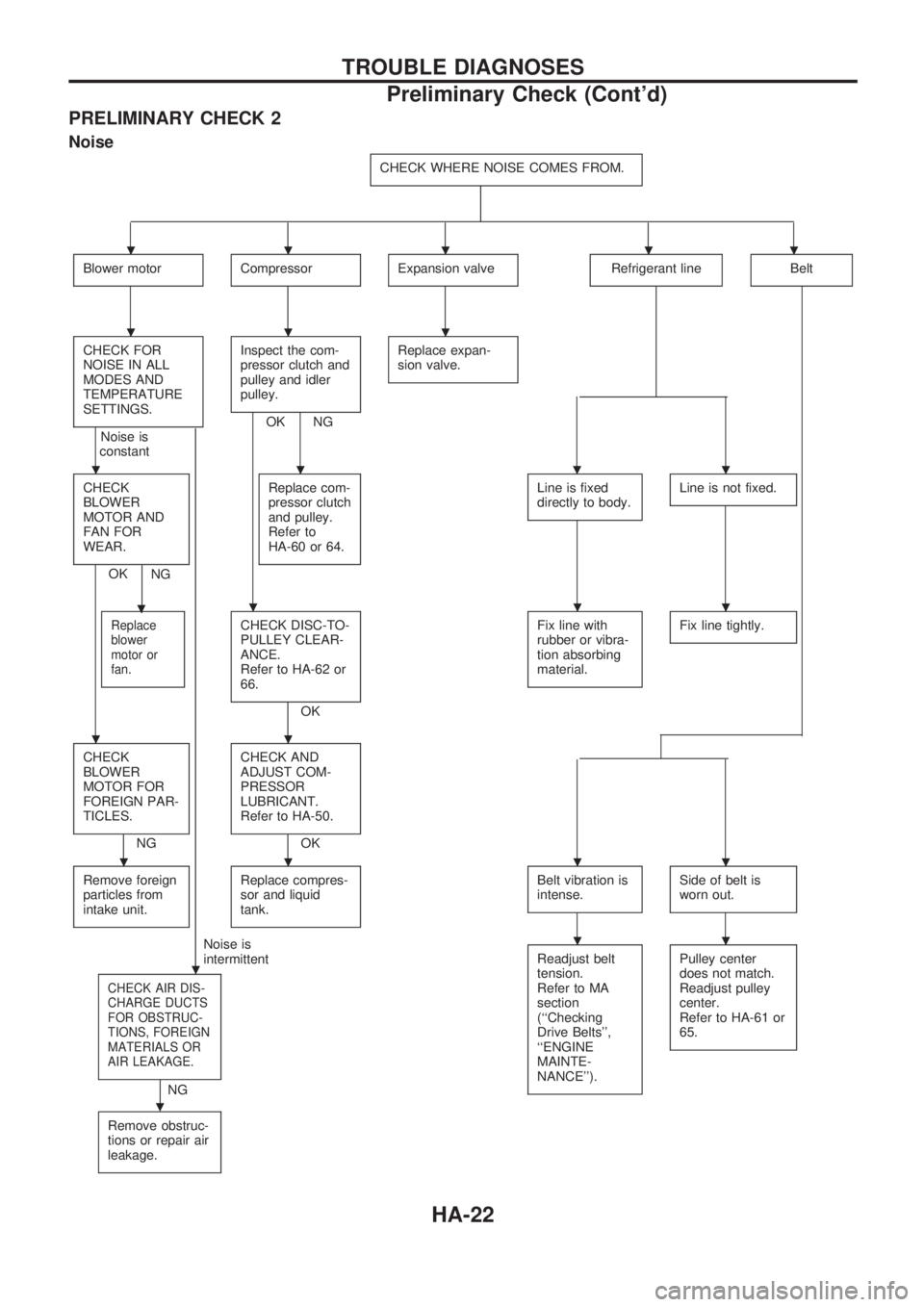
PRELIMINARY CHECK 2
Noise
CHECK WHERE NOISE COMES FROM.
Blower motorCompressorExpansion valveRefrigerant lineBelt
CHECK FOR
NOISE IN ALL
MODES AND
TEMPERATURE
SETTINGS.
Noise is
constant
.
Inspect the com-
pressor clutch and
pulley and idler
pulley.
OK NGReplace expan-
sion valve.
CHECK
BLOWER
MOTOR AND
FAN FOR
WEAR.
OK
.
NGReplace com-
pressor clutch
and pulley.
Refer to
HA-60 or 64.
Line is fixed
directly to body.Line is not fixed.
Replace
blower
motor or
fan.CHECK DISC-TO-
PULLEY CLEAR-
ANCE.
Refer to HA-62 or
66.
OKFix line with
rubber or vibra-
tion absorbing
material.
Fix line tightly.
CHECK
BLOWER
MOTOR FOR
FOREIGN PAR-
TICLES.
NGCHECK AND
ADJUST COM-
PRESSOR
LUBRICANT.
Refer to HA-50.OK
Remove foreign
particles from
intake unit.
Replace compres-
sor and liquid
tank.Belt vibration is
intense.Side of belt is
worn out.
Noise is
intermittent
CHECK AIR DIS-
CHARGE DUCTS
FOR OBSTRUC-
TIONS, FOREIGN
MATERIALS OR
AIR LEAKAGE.
.
NGReadjust belt
tension.
Refer to MA
section
(``Checking
Drive Belts'',
``ENGINE
MAINTE-
NANCE'').
Pulley center
does not match.
Readjust pulley
center.
Refer to HA-61 or
65.
Remove obstruc-
tions or repair air
leakage.
.....
...
....
...
..
....
..
TROUBLE DIAGNOSES
Preliminary Check (Cont'd)
HA-22
Page 896 of 1659
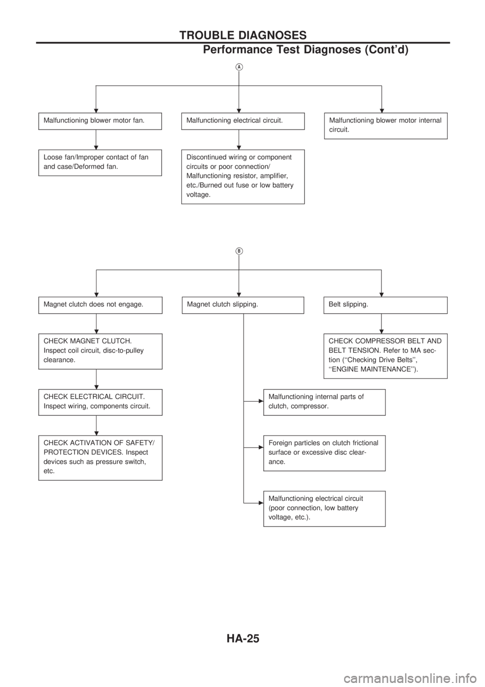
VA
Malfunctioning blower motor fan.Malfunctioning electrical circuit.Malfunctioning blower motor internal
circuit.
Loose fan/Improper contact of fan
and case/Deformed fan.Discontinued wiring or component
circuits or poor connection/
Malfunctioning resistor, amplifier,
etc./Burned out fuse or low battery
voltage.
VB
Magnet clutch does not engage.Magnet clutch slipping.Belt slipping.
CHECK MAGNET CLUTCH.
Inspect coil circuit, disc-to-pulley
clearance.CHECK COMPRESSOR BELT AND
BELT TENSION. Refer to MA sec-
tion (``Checking Drive Belts'',
``ENGINE MAINTENANCE'').
CHECK ELECTRICAL CIRCUIT.
Inspect wiring, components circuit.cMalfunctioning internal parts of
clutch, compressor.
CHECK ACTIVATION OF SAFETY/
PROTECTION DEVICES. Inspect
devices such as pressure switch,
etc.cForeign particles on clutch frictional
surface or excessive disc clear-
ance.
cMalfunctioning electrical circuit
(poor connection, low battery
voltage, etc.).
...
..
...
..
.
.
TROUBLE DIAGNOSES
Performance Test Diagnoses (Cont'd)
HA-25
Page 938 of 1659
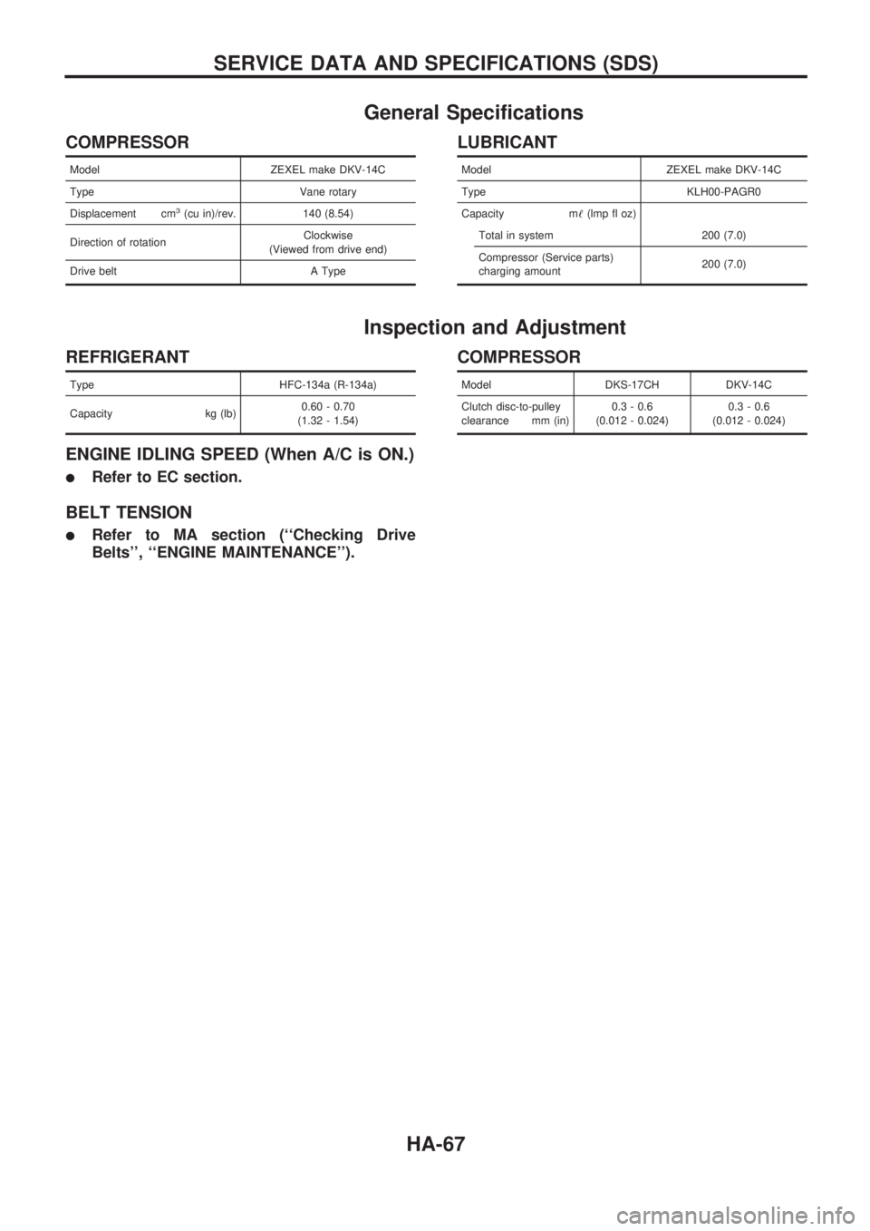
General Specifications
COMPRESSOR
Model ZEXEL make DKV-14C
Type Vane rotary
Displacement cm
3(cu in)/rev. 140 (8.54)
Direction of rotationClockwise
(Viewed from drive end)
Drive belt A Type
LUBRICANT
Model ZEXEL make DKV-14C
Type KLH00-PAGR0
Capacity m!(lmp fl oz)
Total in system 200 (7.0)
Compressor (Service parts)
charging amount200 (7.0)
Inspection and Adjustment
REFRIGERANT
Type HFC-134a (R-134a)
Capacity kg (lb)0.60 - 0.70
(1.32 - 1.54)
ENGINE IDLING SPEED (When A/C is ON.)
lRefer to EC section.
BELT TENSION
lRefer to MA section (``Checking Drive
Belts'', ``ENGINE MAINTENANCE'').
COMPRESSOR
Model DKS-17CH DKV-14C
Clutch disc-to-pulley
clearance mm (in)0.3 - 0.6
(0.012 - 0.024)0.3 - 0.6
(0.012 - 0.024)
SERVICE DATA AND SPECIFICATIONS (SDS)
HA-67