Page 427 of 1659
DIESEL ENGINE MODELS
Check the fol-
lowing:
lWarning
lamp bulb
lFuse for
warning lamp
Ignition switch
``ON''Warning lamp
``OFF''Disconnect connector (S, L) and
ground L harness side.Warning lamp
``OFF''
Warning lamp
``ON''Damaged IC
regulator.
Replace.
Warning lamp
``ON''
Engine idlingWarning lamp
``ON''Check the fol-
lowing:
lDrive beltlField circuit
Check the fol-
lowing:
lFuse for S
terminal
lOpen circuit
for S terminal
lIC regulator
Warning lamp
``OFF''Engine speed: 1,500 rpm
(Measure B terminal voltage)More than
15.5V
13 - 15VOK
Warning lamp: ``CHARGE'' warning lamp in combination meter
Note:
lIf the inspection result is OK even though the charging system is malfunctioning, check the B
terminal connection (check the tightening torque).
lWhen field circuit is open, check condition of rotor coil, rotor slip ring and brush. If necessary,
replace faulty parts with new ones.
CHARGING SYSTEM
Trouble Diagnoses (Cont'd)
EL-37
Page 658 of 1659
CAUTION:
lAfter removing timing chain, do not turn crankshaft and
camshaft separately, or valves will strike piston heads.
lWhen installing rocker arms, camshafts, chain
tensioner, oil seals, or other sliding parts, lubricate con-
tacting surfaces with new engine oil.
lApply new engine oil to bolt threads and seat surfaces
when installing cylinder head, camshaft sprockets,
crankshaft pulley, and camshaft brackets.
Removal
1. Disconnect battery terminal.
2. Remove air cleaner and air intake duct.
3. Drain coolant by removing cylinder block drain plug and
radiator drain cock.
4. Remove heater hose and radiator hoses.
5. Remove radiator with shroud and cooling fan.
6. Remove the following belts.
lPower steering drive belt
lCompressor drive belt
lAlternator drive belt
7. Remove accel control wire.
8. Disconnect exhaust manifold from exhaust front tube.
SEM571FA
TIMING CHAINKA
EM-13
Page 670 of 1659

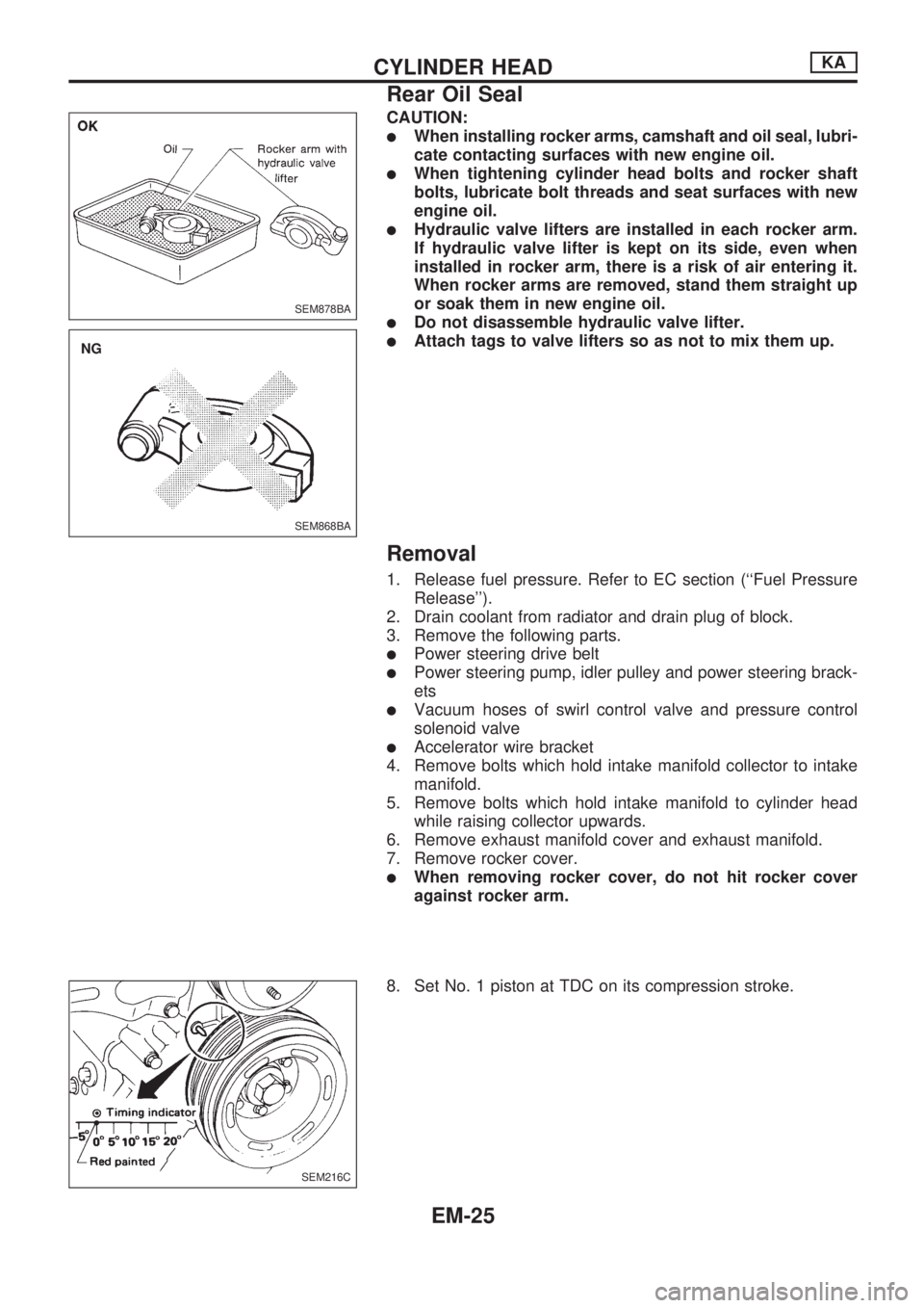
CAUTION:
lWhen installing rocker arms, camshaft and oil seal, lubri-
cate contacting surfaces with new engine oil.
lWhen tightening cylinder head bolts and rocker shaft
bolts, lubricate bolt threads and seat surfaces with new
engine oil.
lHydraulic valve lifters are installed in each rocker arm.
If hydraulic valve lifter is kept on its side, even when
installed in rocker arm, there is a risk of air entering it.
When rocker arms are removed, stand them straight up
or soak them in new engine oil.
lDo not disassemble hydraulic valve lifter.
lAttach tags to valve lifters so as not to mix them up.
Removal
1. Release fuel pressure. Refer to EC section (``Fuel Pressure
Release'').
2. Drain coolant from radiator and drain plug of block.
3. Remove the following parts.
lPower steering drive belt
lPower steering pump, idler pulley and power steering brack-
ets
lVacuum hoses of swirl control valve and pressure control
solenoid valve
lAccelerator wire bracket
4. Remove bolts which hold intake manifold collector to intake
manifold.
5. Remove bolts which hold intake manifold to cylinder head
while raising collector upwards.
6. Remove exhaust manifold cover and exhaust manifold.
7. Remove rocker cover.
lWhen removing rocker cover, do not hit rocker cover
against rocker arm.
8. Set No. 1 piston at TDC on its compression stroke.
SEM878BA
SEM868BA
.NG
SEM216C
CYLINDER HEADKA
Rear Oil Seal
EM-25
Page 682 of 1659

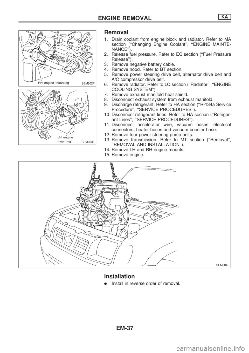
Removal
1. Drain coolant from engine block and radiator. Refer to MA
section (``Changing Engine Coolant'', ``ENGINE MAINTE-
NANCE'').
2. Release fuel pressure. Refer to EC section (``Fuel Pressure
Release'').
3. Remove negative battery cable.
4. Remove hood. Refer to BT section.
5. Remove power steering drive belt, alternator drive belt and
A/C compressor drive belt.
6. Remove radiator. Refer to LC section (``Radiator'', ``ENGINE
COOLING SYSTEM'').
7. Remove exhaust manifold heat shield.
8. Disconnect exhaust system from exhaust manifold.
9. Discharge refrigerant. Refer to HA section (``R-134a Service
Procedure'', ``SERVICE PROCEDURES'').
10. Disconnect refrigerant lines. Refer to HA section (``Refriger-
ant Lines'', ``SERVICE PROCEDURES'').
11. Disconnect accelerator wire, vacuum hoses, electrical
connectors, heater hoses and vacuum booster hose.
12. Remove four power steering pump bolts.
13. Remove transmission. Refer to MT section (``Removal'',
``REMOVAL AND INSTALLATION'').
14. Remove LH and RH engine mounts.
15. Remove engine.
Installation
lInstall in reverse order of removal.
SEM602F
SEM603F
SEM604F
ENGINE REMOVALKA
EM-37
Page 712 of 1659

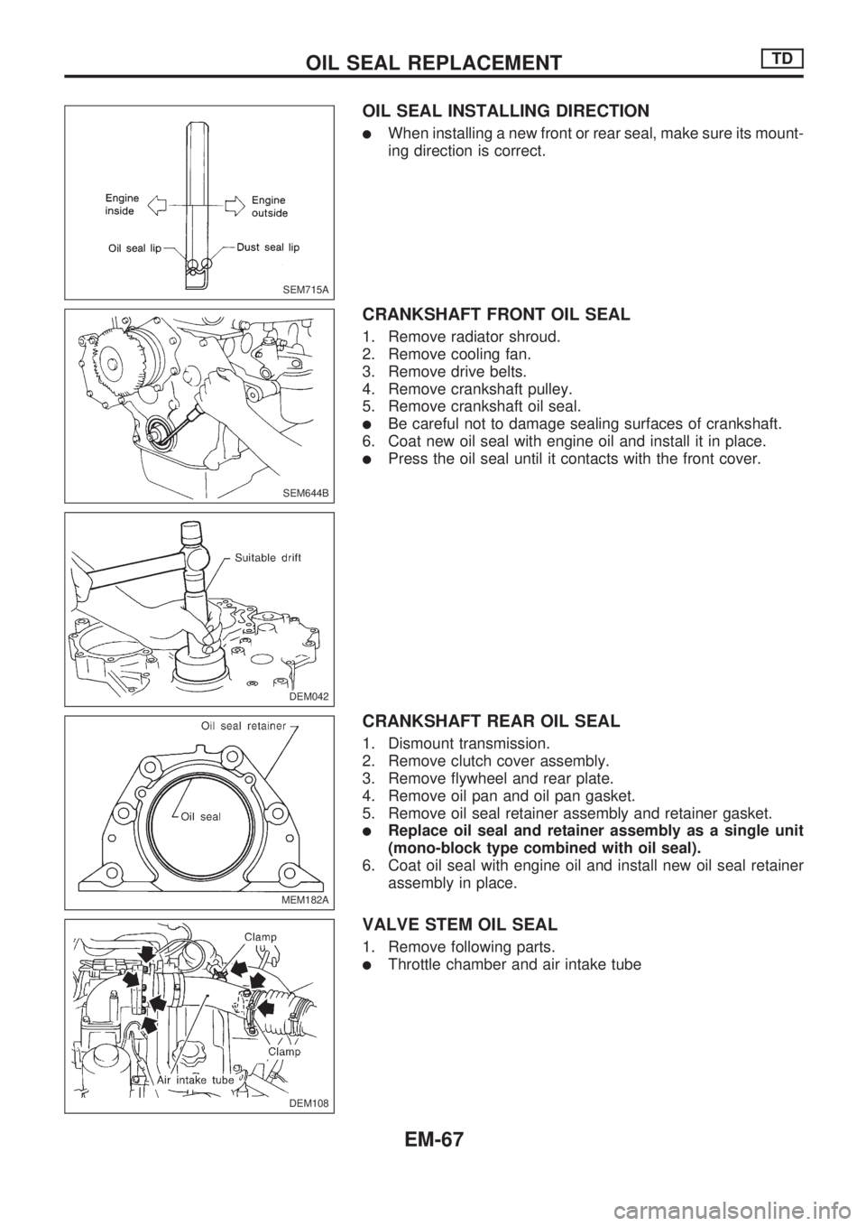
OIL SEAL INSTALLING DIRECTION
lWhen installing a new front or rear seal, make sure its mount-
ing direction is correct.
CRANKSHAFT FRONT OIL SEAL
1. Remove radiator shroud.
2. Remove cooling fan.
3. Remove drive belts.
4. Remove crankshaft pulley.
5. Remove crankshaft oil seal.
lBe careful not to damage sealing surfaces of crankshaft.
6. Coat new oil seal with engine oil and install it in place.
lPress the oil seal until it contacts with the front cover.
CRANKSHAFT REAR OIL SEAL
1. Dismount transmission.
2. Remove clutch cover assembly.
3. Remove flywheel and rear plate.
4. Remove oil pan and oil pan gasket.
5. Remove oil seal retainer assembly and retainer gasket.
lReplace oil seal and retainer assembly as a single unit
(mono-block type combined with oil seal).
6. Coat oil seal with engine oil and install new oil seal retainer
assembly in place.
VALVE STEM OIL SEAL
1. Remove following parts.
lThrottle chamber and air intake tube
SEM715A
SEM644B
DEM042
MEM182A
DEM108
.
OIL SEAL REPLACEMENTTD
EM-67
Page 715 of 1659
Removal
1. Remove engine undercover and hood.
2. Drain engine coolant.
3. Remove vacuum hoses, fuel tubes, wires, harnesses and
connectors and so on.
4. Remove radiator, shroud and cooling fan.
5. Remove drive belts.
6. Remove power steering oil pump and air conditioner com-
pressor.
7. Remove front exhaust tube.
8. Remove transmission from vehicle.
Refer to MT section.
9. Install engine slingers.
10. Hoist engine with engine slingers and remove engine mount-
ing bolts from both sides.
11. Remove engine from vehicle.
Installation
lInstall in reverse order of removal.
DEM021
ENGINE REMOVALTD
EM-70
Page 717 of 1659
Disassembly
PISTON AND CRANKSHAFT
1. Remove oil filter.
2. Place engine on work stand.
3. Drain coolant and oil.
4. Remove drive belts.
5. Remove cylinder head.
6. Remove oil pan.
7. Remove crankshaft pulley.
8. Remove water pump.
9. Remove timing gear case.
lRemove dust cover with a seal cutter.
lIf the timing case is hard to remove due to liquid gasket,
pry it off with a suitable tool at the cutout section.
SEM650B
SEM651B
DEM045
DEM062
DEM046
ENGINE OVERHAULTD
EM-72
Page 805 of 1659

Observe the following precautions to ensure safe and
proper servicing. These precautions are not described in
each individual section.
Precautions for Supplemental Restraint
System (SRS) ``AIR BAG'' (4WD models)
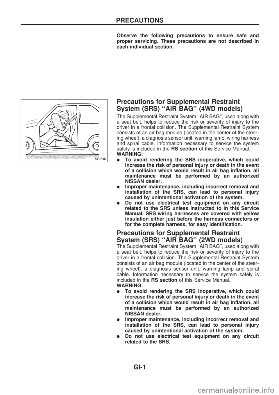
The Supplemental Restraint System ``AIR BAG'', used along with
a seat belt, helps to reduce the risk or severity of injury to the
driver in a frontal collision. The Supplemental Restraint System
consists of an air bag module (located in the center of the steer-
ing wheel), a diagnosis sensor unit, warning lamp, wiring harness
and spiral cable. Information necessary to service the system
safely is included in theRS sectionof this Service Manual.
WARNING:
lTo avoid rendering the SRS inoperative, which could
increase the risk of personal injury or death in the event
of a collision which would result in air bag inflation, all
maintenance must be performed by an authorized
NISSAN dealer.
lImproper maintenance, including incorrect removal and
installation of the SRS, can lead to personal injury
caused by unintentional activation of the system.
lDo not use electrical test equipment on any circuit
related to the SRS unless instructed to in this Service
Manual. SRS wiring harnesses are covered with yellow
insulation either just before the harness connectors or
for the complete harness, for easy identification.
Precautions for Supplemental Restraint
System (SRS) ``AIR BAG'' (2WD models)
The Supplemental Restraint System ``AIR BAG'', used along with
a seat belt, helps to reduce the risk or severity of injury to the
driver in a frontal collision. The Supplemental Restraint System
consists of an air bag module (located in the center of the steer-
ing wheel), a diagnosis sensor unit, warning lamp and spiral
cable. Information necessary to service the system safely is
included in theRS sectionof this Service Manual.
WARNING:
lTo avoid rendering the SRS inoperative, which could
increase the risk of personal injury or death in the event
of a collision which would result in air bag inflation, all
maintenance must be performed by an authorized
NISSAN dealer.
lImproper maintenance, including incorrect removal and
installation of the SRS, can lead to personal injury
caused by unintentional activation of the system.
lDo not use electrical test equipment on any circuit
related to the SRS.
SGI646
PRECAUTIONS
GI-1