1998 NISSAN PICK-UP belt
[x] Cancel search: beltPage 989 of 1659
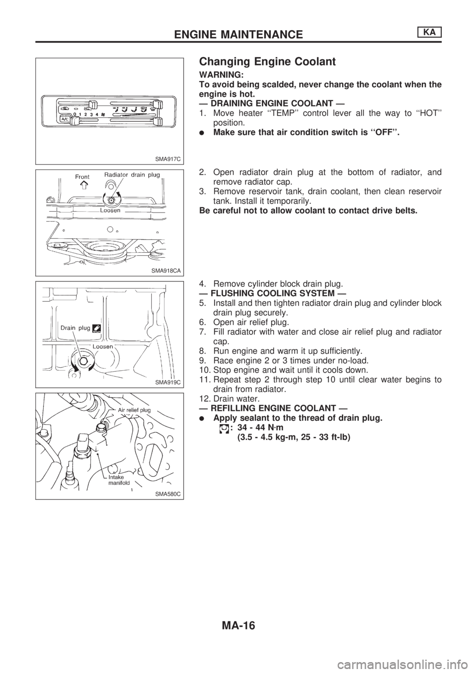
Changing Engine Coolant
WARNING:
To avoid being scalded, never change the coolant when the
engine is hot.
Ð DRAINING ENGINE COOLANT Ð
1. Move heater ``TEMP'' control lever all the way to ``HOT''
position.
lMake sure that air condition switch is ``OFF''.
2. Open radiator drain plug at the bottom of radiator, and
remove radiator cap.
3. Remove reservoir tank, drain coolant, then clean reservoir
tank. Install it temporarily.
Be careful not to allow coolant to contact drive belts.
4. Remove cylinder block drain plug.
Ð FLUSHING COOLING SYSTEM Ð
5. Install and then tighten radiator drain plug and cylinder block
drain plug securely.
6. Open air relief plug.
7. Fill radiator with water and close air relief plug and radiator
cap.
8. Run engine and warm it up sufficiently.
9. Race engine 2 or 3 times under no-load.
10. Stop engine and wait until it cools down.
11. Repeat step 2 through step 10 until clear water begins to
drain from radiator.
12. Drain water.
Ð REFILLING ENGINE COOLANT Ð
lApply sealant to the thread of drain plug.
: 34-44Nzm
(3.5 - 4.5 kg-m, 25 - 33 ft-lb)
SMA917C
SMA918CA
SMA919C
SMA580C
ENGINE MAINTENANCEKA
MA-16
Page 996 of 1659
![NISSAN PICK-UP 1998 Repair Manual Checking Manifold Tightening Torque
Checking should be performed while engine is cold
[approximately 20ÉC (68ÉF)].
Manifold bolts and nuts:
Intake
: 13 - 19 N´m (1.3 - 1.9 kg-m,9-14ft-lb)
Exhaust
: NISSAN PICK-UP 1998 Repair Manual Checking Manifold Tightening Torque
Checking should be performed while engine is cold
[approximately 20ÉC (68ÉF)].
Manifold bolts and nuts:
Intake
: 13 - 19 N´m (1.3 - 1.9 kg-m,9-14ft-lb)
Exhaust
:](/manual-img/5/57374/w960_57374-995.png)
Checking Manifold Tightening Torque
Checking should be performed while engine is cold
[approximately 20ÉC (68ÉF)].
Manifold bolts and nuts:
Intake
: 13 - 19 N´m (1.3 - 1.9 kg-m,9-14ft-lb)
Exhaust
: 25 - 29 N´m (2.5 - 3.0 kg-m, 18 - 22 ft-lb)
Exhaust tube nuts:
: 41.2 - 48.0 N´m (4.2 - 4.9 kg-m, 30 - 35 ft-lb)
Adjusting Intake and Exhaust Valve
Clearance
Adjustment should be made while engine is warm but not
running.
1. Set No. 1 cylinder in top dead center on its compression
stroke, and adjust valve clearance
V1,V2,V3andV6.
2. Set No. 4 cylinder at top dead center on its compression
stroke, and adjust valve clearance
V4,V5,V7andV8.
Valve clearance:
Intake
V1,V3,V5andV7
0.30 - 0.40 mm (0.012 - 0.016 in)
Exhaust
V2,V4,V6andV8
0.30 - 0.40 mm (0.012 - 0.016 in)
Adjusting screw lock nuts:
: 15 - 20 N´m (1.5 - 2.0 kg-m, 11 - 14 ft-lb)
lTighten lock nuts, by fixing the adjusting screws using a
minus driver.
Checking Drive Belt
1. Inspect for cracks, fraying, wear or oil adhesion. Replace if
necessary.
The belts should not touch the bottom of the pulley groove.
2. Check drive belt deflection by pushing on the belt midway
between pulleys.
Adjust if belt deflections exceed the limit.
Unit: mm (in)
Used belt deflection
Deflection of new belt
LimitDeflection after
adjustment
Alternator 20 (0.79) 11 - 13 (0.43 - 0.51) 9 - 11 (0.35 - 0.43)
Air conditioner
compressor12 (0.47) 6 - 7.5 (0.236 - 0.295) 5 - 6.5 (0.197 - 0.256)
Power steering oil
pump15 (0.59) 8 - 9.5 (0.315 - 0.374) 7 - 8.5 (0.276 - 0.335)
Applied pushing
force98 N (10 kg, 22 lb)
Check drive belt deflections when engine is cold.
SMA653C
SMA613C
ENGINE MAINTENANCETD
MA-23
Page 998 of 1659
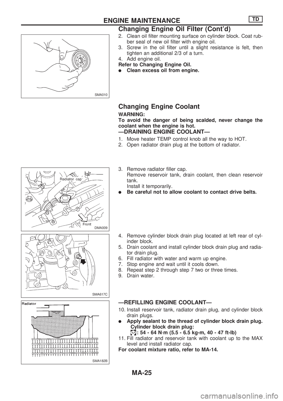
2. Clean oil filter mounting surface on cylinder block. Coat rub-
ber seal of new oil filter with engine oil.
3. Screw in the oil filter until a slight resistance is felt, then
tighten an additional 2/3 of a turn.
4. Add engine oil.
Refer to Changing Engine Oil.
lClean excess oil from engine.
Changing Engine Coolant
WARNING:
To avoid the danger of being scalded, never change the
coolant when the engine is hot.
ÐDRAINING ENGINE COOLANTÐ
1. Move heater TEMP control knob all the way to HOT.
2. Open radiator drain plug at the bottom of radiator.
3. Remove radiator filler cap.
Remove reservoir tank, drain coolant, then clean reservoir
tank.
Install it temporarily.
lBe careful not to allow coolant to contact drive belts.
4. Remove cylinder block drain plug located at left rear of cyl-
inder block.
5. Drain coolant and install cylinder block drain plug and radia-
tor drain plug.
6. Fill radiator with water and warm up engine.
7. Stop engine and wait until it cools down.
8. Repeat step 2 through step 7 two or three times.
9. Drain water.
ÐREFILLING ENGINE COOLANTÐ
10. Install reservoir tank, radiator drain plug, and cylinder block
drain plugs.
lApply sealant to the thread of cylinder block drain plug.
Cylinder block drain plug:
: 54 - 64 N´m (5.5 - 6.5 kg-m, 40 - 47 ft-lb)
11. Fill radiator and reservoir tank with coolant up to the MAX
level and install radiator cap.
For coolant mixture ratio, refer to MA-14.
SMA010
DMA009
SMA617C
SMA182B
ENGINE MAINTENANCETD
Changing Engine Oil Filter (Cont'd)
MA-25
Page 1013 of 1659
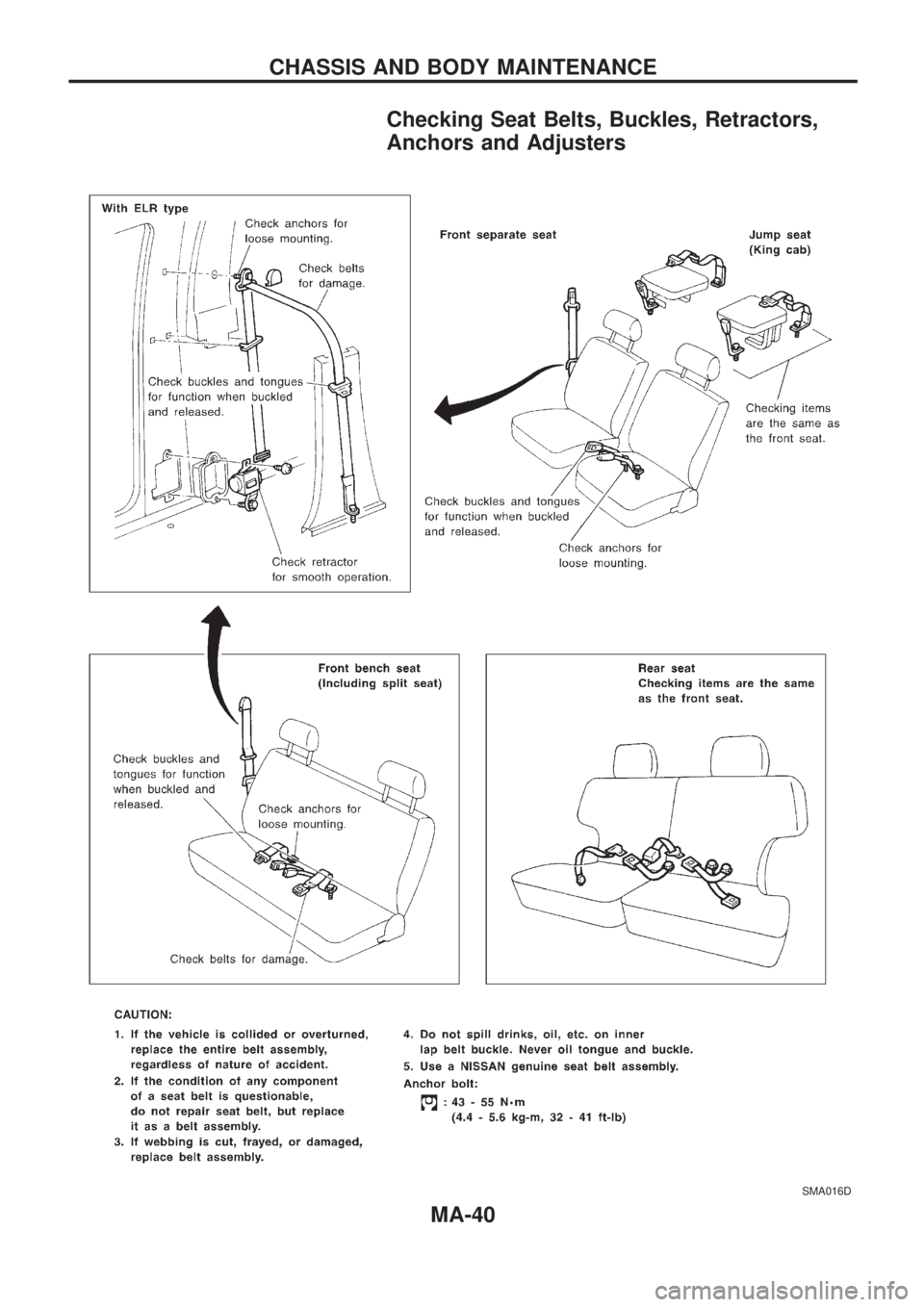
Checking Seat Belts, Buckles, Retractors,
Anchors and Adjusters
SMA016D
CHASSIS AND BODY MAINTENANCE
MA-40
Page 1015 of 1659
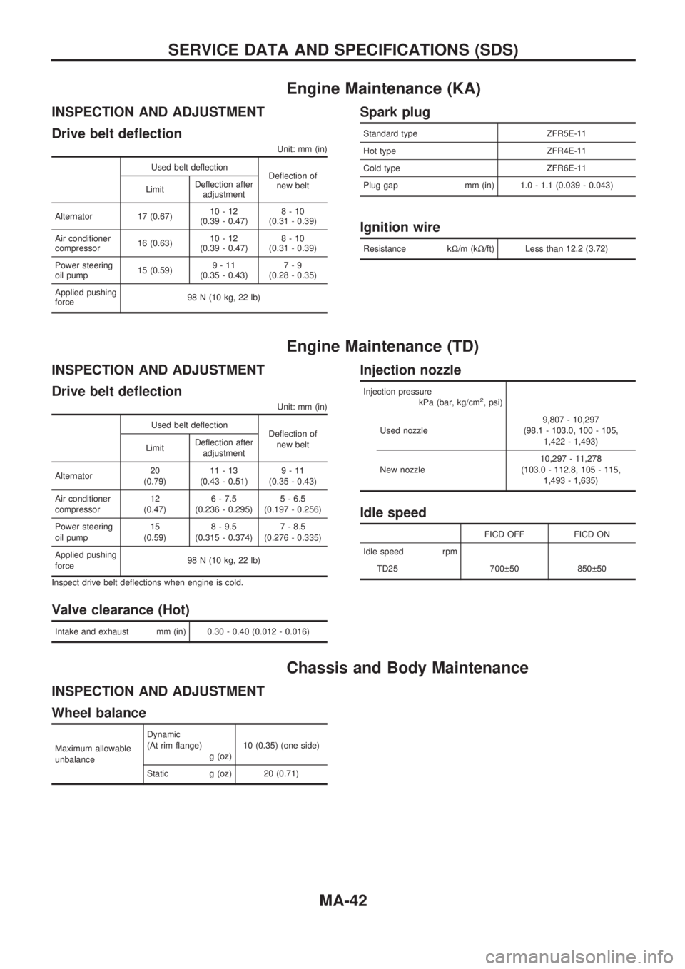
Engine Maintenance (KA)
INSPECTION AND ADJUSTMENT
Drive belt deflection
Unit: mm (in)
Used belt deflection
Deflection of
new belt
LimitDeflection after
adjustment
Alternator 17 (0.67)10-12
(0.39 - 0.47)8-10
(0.31 - 0.39)
Air conditioner
compressor16 (0.63)10-12
(0.39 - 0.47)8-10
(0.31 - 0.39)
Power steering
oil pump15 (0.59)9-11
(0.35 - 0.43)7-9
(0.28 - 0.35)
Applied pushing
force98 N (10 kg, 22 lb)
Spark plug
Standard type ZFR5E-11
Hot type ZFR4E-11
Cold type ZFR6E-11
Plug gap mm (in) 1.0 - 1.1 (0.039 - 0.043)
Ignition wire
Resistance kW/m (kW/ft) Less than 12.2 (3.72)
Engine Maintenance (TD)
INSPECTION AND ADJUSTMENT
Drive belt deflection
Unit: mm (in)
Used belt deflection
Deflection of
new belt
LimitDeflection after
adjustment
Alternator20
(0.79)11-13
(0.43 - 0.51)9-11
(0.35 - 0.43)
Air conditioner
compressor12
(0.47)6 - 7.5
(0.236 - 0.295)5 - 6.5
(0.197 - 0.256)
Power steering
oil pump15
(0.59)8 - 9.5
(0.315 - 0.374)7 - 8.5
(0.276 - 0.335)
Applied pushing
force98 N (10 kg, 22 lb)
Inspect drive belt deflections when engine is cold.
Valve clearance (Hot)
Intake and exhaust mm (in) 0.30 - 0.40 (0.012 - 0.016)
Injection nozzle
Injection pressure
kPa (bar, kg/cm2, psi)
Used nozzle9,807 - 10,297
(98.1 - 103.0, 100 - 105,
1,422 - 1,493)
New nozzle10,297 - 11,278
(103.0 - 112.8, 105 - 115,
1,493 - 1,635)
Idle speed
FICD OFF FICD ON
Idle speed rpm
TD25 700 50 850 50
Chassis and Body Maintenance
INSPECTION AND ADJUSTMENT
Wheel balance
Maximum allowable
unbalanceDynamic
(At rim flange)
g (oz)10 (0.35) (one side)
Static g (oz) 20 (0.71)
SERVICE DATA AND SPECIFICATIONS (SDS)
MA-42
Page 1163 of 1659
RESTRAINT SYSTEM
SECTION
RS
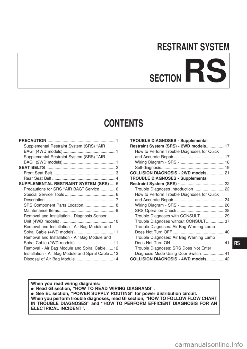
CONTENTS
PRECAUTION............................................................ 1
Supplemental Restraint System (SRS) ``AIR
BAG'' (4WD models).............................................. 1
Supplemental Restraint System (SRS) ``AIR
BAG'' (2WD models).............................................. 1
SEAT BELTS............................................................. 2
Front Seat Belt ....................................................... 3
Rear Seat Belt ....................................................... 4
SUPPLEMENTAL RESTRAINT SYSTEM (SRS)..... 6
Precautions for SRS ``AIR BAG'' Service .............. 6
Special Service Tools ............................................ 6
Description ............................................................. 7
SRS Component Parts Location............................ 8
Maintenance Items................................................. 9
Removal and Installation - Diagnosis Sensor
Unit (4WD models) .............................................. 10
Removal and Installation - Air Bag Module and
Spiral Cable (4WD models) ................................. 11
Removal and Installation - Air Bag Module and
Spiral Cable (2WD models) ................................. 11
Removal - Air Bag Module and Spiral Cable ...... 12
Installation - Air Bag Module and Spiral Cable ... 13
Disposal of Air Bag Module ................................. 14TROUBLE DIAGNOSES - Supplemental
Restraint System (SRS) - 2WD models................ 17
How to Perform Trouble Diagnoses for Quick
and Accurate Repair ............................................ 17
Wiring Diagram - SRS - ....................................... 18
Self-diagnosis....................................................... 19
COLLISION DIAGNOSIS - 2WD models............... 21
TROUBLE DIAGNOSES - Supplemental
Restraint System (SRS) -....................................... 22
Trouble Diagnoses Introduction ........................... 22
How to Perform Trouble Diagnoses for Quick
and Accurate Repair ............................................ 24
Wiring Diagram - SRS - ....................................... 26
SRS Operation Check ......................................... 28
Trouble Diagnoses with CONSULT ..................... 29
Trouble Diagnoses without CONSULT ................ 37
Trouble Diagnoses: Air Bag Warning Lamp
Does Not Turn OFF ............................................. 40
Trouble Diagnoses: Air Bag Warning Lamp
Does Not Turn ON ............................................... 41
Trouble Diagnoses: SRS Does Not Enter
Diagnosis Mode Using Door Switch .................... 41
COLLISION DIAGNOSIS - 4WD models............... 42
When you read wiring diagrams:
lRead GI section, ``HOW TO READ WIRING DIAGRAMS''.
lSee EL section, ``POWER SUPPLY ROUTING'' for power distribution circuit.
When you perform trouble diagnoses, read GI section, ``HOW TO FOLLOW FLOW CHART
IN TROUBLE DIAGNOSES'' and ``HOW TO PERFORM EFFICIENT DIAGNOSIS FOR AN
ELECTRICAL INCIDENT''.
RS
Page 1164 of 1659
Supplemental Restraint System (SRS) ``AIR
BAG'' (4WD models)
The Supplemental Restraint System ``AIR BAG'', used along with a seat belt, helps to reduce the risk or
severity of injury to the driver in a frontal collision. The Supplemental Restraint System consists of air bag
module (located in the center of the steering wheel), diagnosis sensor unit, warning lamp, wiring harness
and spiral cable.
WARNING:
lTo avoid rendering the SRS inoperative, which could increase the risk of personal injury or death
in the event of a collision which would result in air bag inflation, all maintenance must be per-
formed by an authorized NISSAN dealer.
lImproper maintenance, including incorrect removal and installation of the SRS, can lead to per-
sonal injury caused by unintentional activation of the system.
lDo not use electrical test equipment on any circuit related to the SRS unless instructed to in this
Service Manual. SRS wiring harnesses are covered with yellow insulation either just before the
harness connectors or for the complete harness, for easy identification.
Supplemental Restraint System (SRS) ``AIR
BAG'' (2WD models)
The Supplemental Restraint System ``AIR BAG'', used along with a seat belt, helps to reduce the risk or
severity of injury to the driver in a frontal collision. The Supplemental Restraint System consists of air bag
module (located in the center of the steering wheel), diagnosis sensor unit, warning lamp, wiring harness
and spiral cable.
WARNING:
lTo avoid rendering the SRS inoperative, which could increase the risk of personal injury or death
in the event of a collision which would result in air bag inflation, all maintenance must be per-
formed by an authorized NISSAN dealer.
lImproper maintenance, including incorrect removal and installation of the SRS, can lead to per-
sonal injury caused by unintentional activation of the system.
lDo not use electrical test equipment on any circuit related to the SRS unless instructed to in this
Service Manual.
PRECAUTION
RS-1
Page 1165 of 1659
CAUTION:
lDo not disassemble buckle or seat belt assembly.
lReplace anchor bolts if they are deformed or worn out.
lNever oil tongue and buckle.
lIf any component of seat belt assembly is questionable, do not repair. Replace the whole seat
belt assembly.
lIf webbing is cut, frayed, or damaged, replace seat belt assembly.
lWhen replacing seat belt assembly, use a genuine seat belt assembly.
lAfter any collision, inspect all seat belt assemblies, including retractors and other attached
hardwares.
SEAT BELTS
RS-2