Page 1312 of 1659

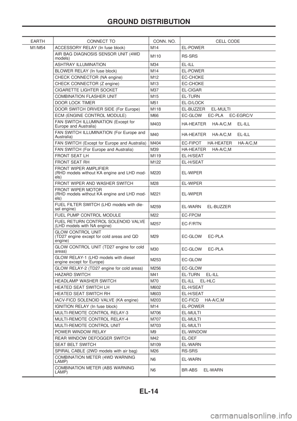
EARTH CONNECT TO CONN. NO. CELL CODE
M1/M54 ACCESSORY RELAY (In fuse block) M14 EL-POWER
AIR BAG DIAGNOSIS SENSOR UNIT (4WD
models)M110 RS-SRS
ASHTRAY ILLUMINATION M34 EL-ILL
BLOWER RELAY (In fuse block) M14 EL-POWER
CHECK CONNECTOR (NA engine) M12 EC-CHOKE
CHECK CONNECTOR (Z engine) M13 EC-CHOKE
CIGARETTE LIGHTER SOCKET M37 EL-CIGAR
COMBINATION FLASHER UNIT M15 EL-TURN
DOOR LOCK TIMER M51 EL-D/LOCK
DOOR SWITCH DRIVER SIDE (For Europe) M118 EL-BUZZER EL-MULTI
ECM (ENGINE CONTROL MODULE) M66 EC-GLOW EC-PLA EC-EGRC/V
FAN SWITCH ILLUMINATION (Except for
Europe and Australia)M403 HA-HEATER HA-A/C,M EL-ILL
FAN SWITCH ILLUMINATION (For Europe and
Australia)M40 HA-HEATER HA-A/C,M EL-ILL
FAN SWITCH (Except for Europe and Australia) M404 EC-FIPOT HA-HEATER HA-A/C,M
FAN SWITCH (For Europe and Australia) M39 HA-HEATER HA-A/C,M
FRONT SEAT LH M119 EL-H/SEAT
FRONT SEAT RH M122 EL-H/SEAT
FRONT WIPER AMPLIFIER
(RHD models without KA engine and LHD mod-
els)M220 EL-WIPER
FRONT WIPER AND WASHER SWITCH M28 EL-WIPER
FRONT WIPER MOTOR
(RHD models without KA engine and LHD mod-
els)M221 EL-WIPER
FUEL FILTER SWITCH (LHD models with die-
sel engine)M259 EL-WARN EL-BUZZER
FUEL PUMP CONTROL MODULE M22 EC-FPCM
FUEL RETURN CONTROL SOLENOID VALVE
(LHD models with NA engine)M257 EC-F/RTN
GLOW CONTROL UNIT
(TD27 engine except for cold areas and QD
engine)M29 EC-GLOW EC-PLA
GLOW CONTROL UNIT (TD27 engine for cold
areas)M30 EC-GLOW EC-PLA
GLOW RELAY-1 (LHD models with diesel
engine except for Europe)M253 EC-GLOW
GLOW RELAY-2 (TD27 engine for cold areas) M256 EC-GLOW
HAZARD SWITCH M41 EL-TURN EL-ILL
HEADLAMP WASHER SWITCH M70 EL-ILL EL-HLC
HEATED SEAT SWITCH LH M602 EL-H/SEAT
HEATED SEAT SWITCH RH M603 EL-H/SEAT
IACV-FICD SOLENOID VALVE (KA engine) M203 EC-FICD HA-A/C,M
IGNITION RELAY (In fuse block) M14 EL-POWER
MULTI-REMOTE CONTROL RELAY-3 M706 EL-MULTI
MULTI-REMOTE CONTROL RELAY-4 M707 EL-MULTI
MULTI-REMOTE CONTROL UNIT M703 EL-MULTI
POWER WINDOW RELAY M9 EL-WINDOW
REAR WINDOW DEFOGGER SWITCH M42 EL-DEF
SEAT BELT SWITCH M109 EL-WARN
SPIRAL CABLE (2WD models with air bag) M26 RS-SRS
COMBINATION METER (4WD WARNING
LAMP)N6 EL-WARN
COMBINATION METER (ABS WARNING
LAMP)N6 BR-ABS EL-WARN
GROUND DISTRIBUTION
EL-14
Page 1334 of 1659

Trouble Diagnoses
Before conducting an alternator test, make sure that the battery is fully charged. A 30-volt voltmeter and
suitable test probes are necessary for the test. The alternator can be checked easily by referring to the
Inspection Table.
lBefore starting, inspect the fusible link.
lUse fully charged battery.
GASOLINE ENGINE MODELS
Check the fol-
lowing:
lWarning
lamp bulb
lFuse for
warning lamp
Ignition switch
``ON''Warning lamp
``OFF''Disconnect connector (S, L) and
ground L harness side.Warning lamp
``OFF''
Warning lamp
``ON''Damaged IC
regulator.
Replace.
Warning lamp
``ON''
Engine start.
Engine speed:
1,500 rpmWarning lamp
``ON''Check the following:lDrive beltlFuse for S terminallConnector (S, L terminal) con-
nection
Engine idlingWarning lamp
``OFF''OK
Warning lamp
``ON''
Warning lamp
``OFF''OKEngine speed:
1,500 rpm
(Measure B
terminal volt-
age)More than
15.5VDamaged IC
regulator.
Replace.
No generationField circuit is
open.
Warning lamp: ``CHARGE'' warning lamp in combination meter
Note:
lIf the inspection result is OK even though the charging system is malfunctioning, check the B
terminal connection. (Check the tightening torque.)
lWhen field circuit is open, check condition of rotor coil, rotor slip ring and brush. If necessary,
replace faulty parts with new ones.
Malfunction indicator
The IC regulator warning function activates to illuminate ``CHARGE'' warning lamp, if any of the following
symptoms occur while alternator is operating:
lField circuit is open.
lExcessive voltage is produced.
CHARGING SYSTEM
EL-36
Page 1335 of 1659
DIESEL ENGINE MODELS
Check the fol-
lowing:
lWarning
lamp bulb
lFuse for
warning lamp
Ignition switch
``ON''Warning lamp
``OFF''Disconnect connector (S, L) and
ground L harness side.Warning lamp
``OFF''
Warning lamp
``ON''Damaged IC
regulator.
Replace.
Warning lamp
``ON''
Engine idlingWarning lamp
``ON''Check the fol-
lowing:
lDrive beltlField circuit
Check the fol-
lowing:
lFuse for S
terminal
lOpen circuit
for S terminal
lIC regulator
Warning lamp
``OFF''Engine speed: 1,500 rpm
(Measure B terminal voltage)More than
15.5V
13 - 15VOK
Warning lamp: ``CHARGE'' warning lamp in combination meter
Note:
lIf the inspection result is OK even though the charging system is malfunctioning, check the B
terminal connection (check the tightening torque).
lWhen field circuit is open, check condition of rotor coil, rotor slip ring and brush. If necessary,
replace faulty parts with new ones.
CHARGING SYSTEM
Trouble Diagnoses (Cont'd)
EL-37
Page 1566 of 1659
CAUTION:
lAfter removing timing chain, do not turn crankshaft and
camshaft separately, or valves will strike piston heads.
lWhen installing rocker arms, camshafts, chain
tensioner, oil seals, or other sliding parts, lubricate con-
tacting surfaces with new engine oil.
lApply new engine oil to bolt threads and seat surfaces
when installing cylinder head, camshaft sprockets,
crankshaft pulley, and camshaft brackets.
Removal
1. Disconnect battery terminal.
2. Remove air cleaner and air intake duct.
3. Drain coolant by removing cylinder block drain plug and
radiator drain cock.
4. Remove heater hose and radiator hoses.
5. Remove radiator with shroud and cooling fan.
6. Remove the following belts.
lPower steering drive belt
lCompressor drive belt
lAlternator drive belt
7. Remove accel control wire.
8. Disconnect exhaust manifold from exhaust front tube.
SEM571FA
TIMING CHAINKA
EM-13
Page 1578 of 1659

CAUTION:
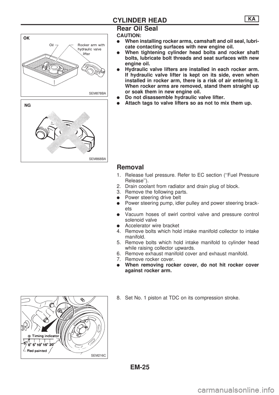
lWhen installing rocker arms, camshaft and oil seal, lubri-
cate contacting surfaces with new engine oil.
lWhen tightening cylinder head bolts and rocker shaft
bolts, lubricate bolt threads and seat surfaces with new
engine oil.
lHydraulic valve lifters are installed in each rocker arm.
If hydraulic valve lifter is kept on its side, even when
installed in rocker arm, there is a risk of air entering it.
When rocker arms are removed, stand them straight up
or soak them in new engine oil.
lDo not disassemble hydraulic valve lifter.
lAttach tags to valve lifters so as not to mix them up.
Removal
1. Release fuel pressure. Refer to EC section (``Fuel Pressure
Release'').
2. Drain coolant from radiator and drain plug of block.
3. Remove the following parts.
lPower steering drive belt
lPower steering pump, idler pulley and power steering brack-
ets
lVacuum hoses of swirl control valve and pressure control
solenoid valve
lAccelerator wire bracket
4. Remove bolts which hold intake manifold collector to intake
manifold.
5. Remove bolts which hold intake manifold to cylinder head
while raising collector upwards.
6. Remove exhaust manifold cover and exhaust manifold.
7. Remove rocker cover.
lWhen removing rocker cover, do not hit rocker cover
against rocker arm.
8. Set No. 1 piston at TDC on its compression stroke.
SEM878BA
SEM868BA
.NG
SEM216C
CYLINDER HEADKA
Rear Oil Seal
EM-25
Page 1590 of 1659

Removal
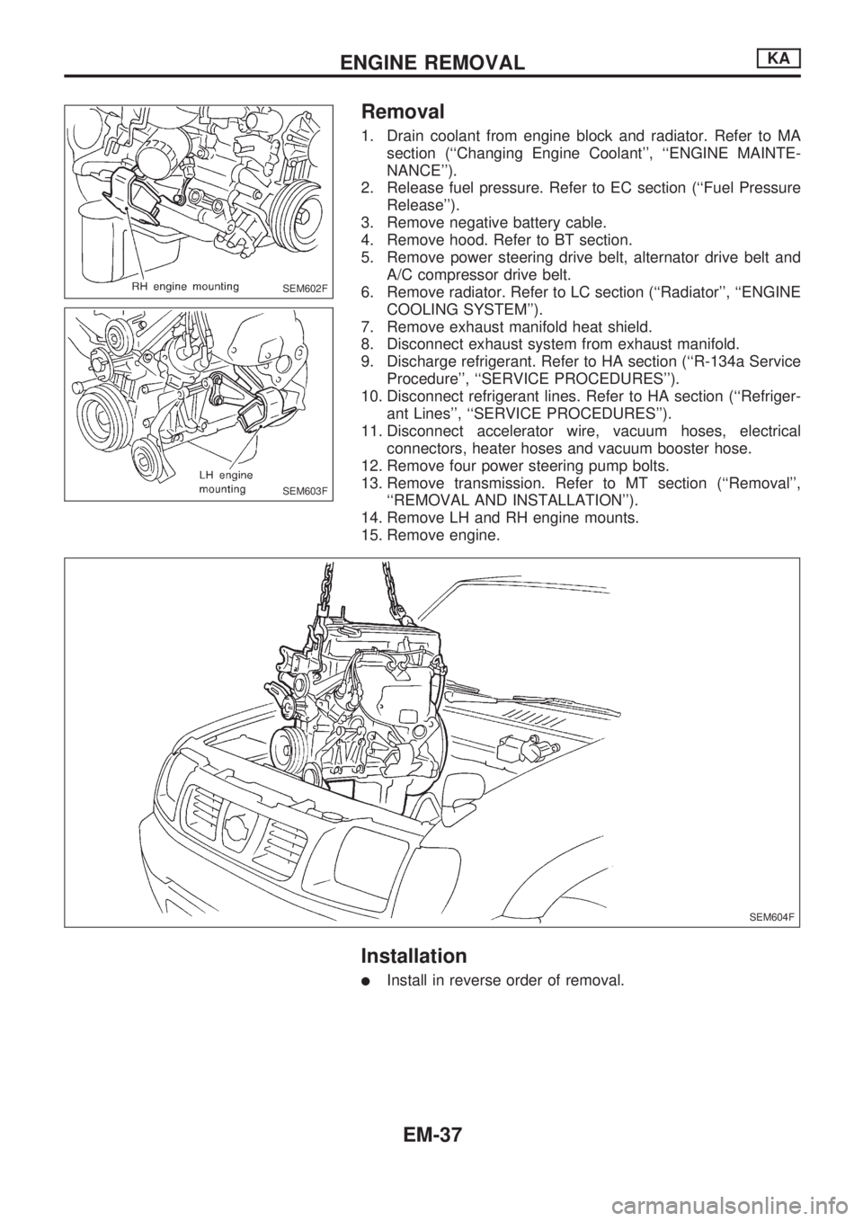
1. Drain coolant from engine block and radiator. Refer to MA
section (``Changing Engine Coolant'', ``ENGINE MAINTE-
NANCE'').
2. Release fuel pressure. Refer to EC section (``Fuel Pressure
Release'').
3. Remove negative battery cable.
4. Remove hood. Refer to BT section.
5. Remove power steering drive belt, alternator drive belt and
A/C compressor drive belt.
6. Remove radiator. Refer to LC section (``Radiator'', ``ENGINE
COOLING SYSTEM'').
7. Remove exhaust manifold heat shield.
8. Disconnect exhaust system from exhaust manifold.
9. Discharge refrigerant. Refer to HA section (``R-134a Service
Procedure'', ``SERVICE PROCEDURES'').
10. Disconnect refrigerant lines. Refer to HA section (``Refriger-
ant Lines'', ``SERVICE PROCEDURES'').
11. Disconnect accelerator wire, vacuum hoses, electrical
connectors, heater hoses and vacuum booster hose.
12. Remove four power steering pump bolts.
13. Remove transmission. Refer to MT section (``Removal'',
``REMOVAL AND INSTALLATION'').
14. Remove LH and RH engine mounts.
15. Remove engine.
Installation
lInstall in reverse order of removal.
SEM602F
SEM603F
SEM604F
ENGINE REMOVALKA
EM-37
Page 1620 of 1659

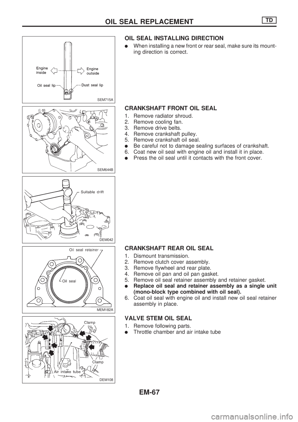
OIL SEAL INSTALLING DIRECTION
lWhen installing a new front or rear seal, make sure its mount-
ing direction is correct.
CRANKSHAFT FRONT OIL SEAL
1. Remove radiator shroud.
2. Remove cooling fan.
3. Remove drive belts.
4. Remove crankshaft pulley.
5. Remove crankshaft oil seal.
lBe careful not to damage sealing surfaces of crankshaft.
6. Coat new oil seal with engine oil and install it in place.
lPress the oil seal until it contacts with the front cover.
CRANKSHAFT REAR OIL SEAL
1. Dismount transmission.
2. Remove clutch cover assembly.
3. Remove flywheel and rear plate.
4. Remove oil pan and oil pan gasket.
5. Remove oil seal retainer assembly and retainer gasket.
lReplace oil seal and retainer assembly as a single unit
(mono-block type combined with oil seal).
6. Coat oil seal with engine oil and install new oil seal retainer
assembly in place.
VALVE STEM OIL SEAL
1. Remove following parts.
lThrottle chamber and air intake tube
SEM715A
SEM644B
DEM042
MEM182A
DEM108
.
OIL SEAL REPLACEMENTTD
EM-67
Page 1623 of 1659
Removal
1. Remove engine undercover and hood.
2. Drain engine coolant.
3. Remove vacuum hoses, fuel tubes, wires, harnesses and
connectors and so on.
4. Remove radiator, shroud and cooling fan.
5. Remove drive belts.
6. Remove power steering oil pump and air conditioner com-
pressor.
7. Remove front exhaust tube.
8. Remove transmission from vehicle.
Refer to MT section.
9. Install engine slingers.
10. Hoist engine with engine slingers and remove engine mount-
ing bolts from both sides.
11. Remove engine from vehicle.
Installation
lInstall in reverse order of removal.
DEM021
ENGINE REMOVALTD
EM-70