1998 JAGUAR X308 lock
[x] Cancel search: lockPage 1831 of 2490
other sensors. This feature prevents the effects of sudden changes in air outlet temperatures due to factors such as:
Recirculating air from the engine cooling pack at low vehicle speeds Sudden changes in ambient temperature The effects of water splash
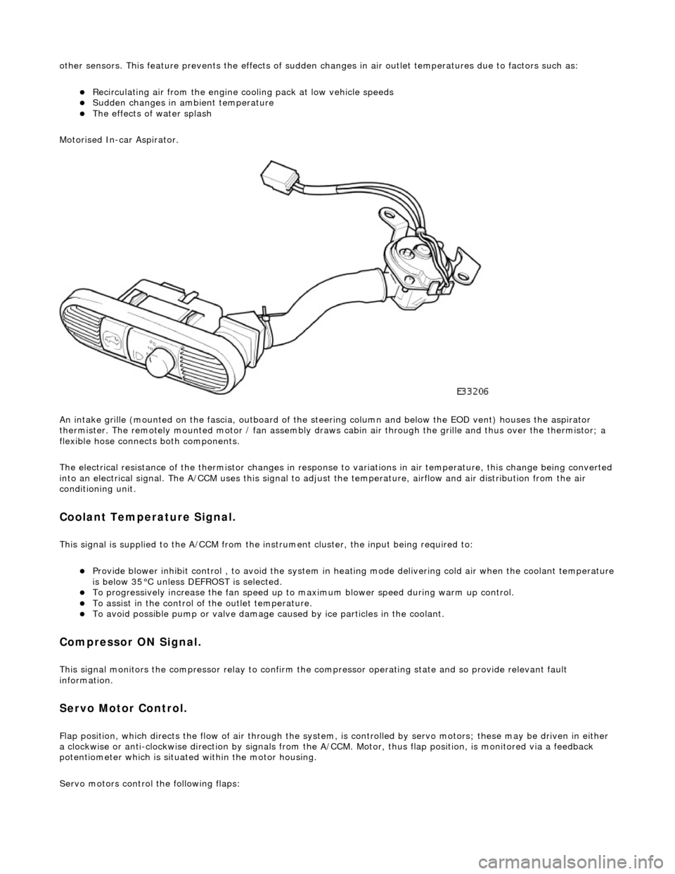
Motorised In-car Aspirator.
An intake grille (mounted on the fascia , outboard of the steering column and below the EOD vent) houses the aspirator
thermister. The remotely mounted motor / fan assembly draws ca bin air through the grille and thus over the thermistor; a
flexible hose connects both components.
The electrical resistance of the thermistor changes in response to variations in air temperatur e, this change being converted
into an electrical signal. The A/CCM uses this signal to adjust the temperature, airflow and air distribution from the air
conditioning unit.
Coolant Temperature Signal.
This signal is supplied to the A/CCM from the instrument cluster, the input being required to:
Provide blower inhibit control , to avoid the system in heat ing mode delivering cold air when the coolant temperature is below 35°C unless DEFROST is selected. To progressively increase the fan speed up to maximum blower speed during warm up control. To assist in the control of the outlet temperature. To avoid possible pump or valve damage ca used by ice particles in the coolant.
Compressor ON Signal.
This signal monitors the compressor relay to confirm the compressor operating state and so provide relevant fault
information.
Servo Motor Control.
Flap position, which directs the flow of air through the system, is controlled by servo motors; these may be driven in either
a clockwise or anti-clockwise direction by signals from the A/ CCM. Motor, thus flap position, is monitored via a feedback
potentiometer which is situated within the motor housing.
Servo motors control the following flaps:
Page 1834 of 2490
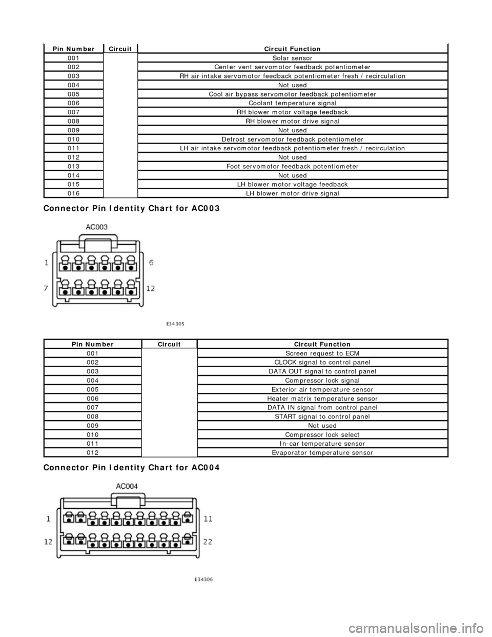
Connector Pin Identity Chart for AC003
Connector Pin Identity Chart for AC004
Pin NumberCircuitCircuit Function
001Solar sensor
002Center vent servomotor feedback potentiometer
003RH air intake servomotor feedback potentiometer fresh / recirculation
004Not used
005Cool air bypass servomotor feedback potentiometer
006Coolant temperature signal
007RH blower motor voltage feedback
008RH blower motor drive signal
009Not used
010Defrost servomotor feedback potentiometer
011LH air intake servomotor feedback potentiometer fresh / recirculation
012Not used
013Foot servomotor feedback potentiometer
014Not used
015LH blower motor voltage feedback
016LH blower motor drive signal
Pin NumberCircuitCircuit Function
001Screen request to ECM
002CLOCK signal to control panel
003DATA OUT signal to control panel
004Compressor lock signal
005Exterior air temperature sensor
006Heater matrix temperature sensor
007DATA IN signal from control panel
008START signal to control panel
009Not used
010Compressor lock select
011In-car temperature sensor
012Evaporator temperature sensor
Page 1835 of 2490
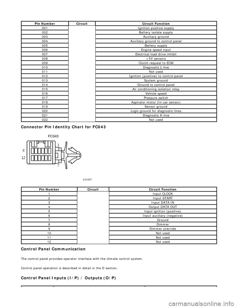
Connector Pin Identity Chart for FC043
Control Panel Communication
The control panel provides operator interface with the climate control system.
Control panel operation is described in detail in the D section.
Control Panel Inputs (I/P) / Outputs (O/P)
Pin NumberCircuitCircuit Function
001Ignition positive supply
002Battery isolate supply
003Auxiliary ground
004Auxiliary ground to control panel
005Battery supply
006Engine speed input
007Electrical load drive inhibit
008+5V sensors
009Clutch request to ECM
010Diagnostic L-line
011Not used
012Ignition (positive) to control panel
013System ground
014Ground to control panel
015Air conditioning isolation relay
016Vehicle speed
017Pressure switch
018Aspirator motor (In-car sensor)
019Sensor ground
020Logic ground for diagnostic lines
021Diagnostic K-line
022Not used
Pin NumberCircuitCircuit Function
1Input CLOCK
2Input START
3Input DATA IN
4Output DATA OUT
5Input ignition (positive)
6Input auxiliary (negative)
7Ground
8Dimmer
9Dimmer override
10Not used
11Not used
12Not used
Page 1836 of 2490
System Self-test
Control Panel Interrogation Procedure
The control panel has a self-diagnosis feature, and is capable of displaying and clearing stored fault codes.
Climate control is an integrated system, therefore it is recommended that the PDU is used for fault diagnosis. The fault
codes displayed with the control panel self -diagnosis feature are not as comprehensive as those of the PDU. The PDU will
display the relevant fault code, fault co de description and information of the system peripherals at the time the fault
occurred.
Fault Code Extraction and Deletion Procedure
Error information is stored in the A/CCM up to a maximum of 5 faults. Should a sensor fault occur there will be an audible
beep and the message Er will be displayed on the control panel display for 5 seco nds after ignition on. Please note that this
will happen only once in any ignition switch cycle. The error source may be accessed by the following procedure
This procedure must be completed through one complete cycle, 1 through 6
• NOTE: * Actuator codes do NOT equate to system fault codes.
• NOTE: Only codes 11, 15 and 21 (see Fault Code List ing) will cause audible beep and 'Er' display.
• NOTE: If '0' is displayed, there are no stored faul t codes, wait 30 seconds to allow system self-test.
The control panel display will flash repeatedly indicating a list of two digit numbers (see table for code analysis). Should a code be displayed accompanied by an audible beep, the fault is current and therefore still present within
the system. A code displayed without an accompanying 'bee p' indicates a fault had previously occurred but is not
present within the system.
• NOTE: It is advisable to check all areas indicated with cleared fault codes. Such faults may re-occur if intermittent
problems are present in the system.
To delete stored and cleared fault codes press 'R' and 'FAC E' buttons simultaneously. After investigating and correcting all stored faults, press the 'Push Off' button to restore normal operation with
default panel settings, ie AUTO at 24°C.
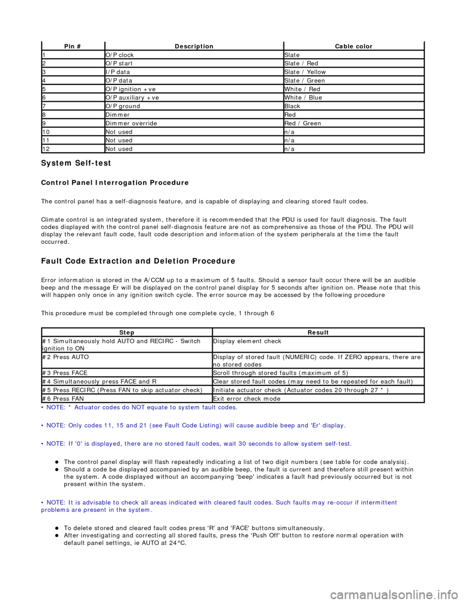
Pin #DescriptionCable color
1O/P clockSlate
2O/P startSlate / Red
3I/P dataSlate / Yellow
4O/P dataSlate / Green
5O/P ignition +veWhite / Red
6O/P auxiliary +veWhite / Blue
7O/P groundBlack
8DimmerRed
9Dimmer overrideRed / Green
10Not usedn/a
11Not usedn/a
12Not usedn/a
StepResult
#1 Simultaneously hold AU TO and RECIRC - Switch
ignition to ONDisplay element check
#2 Press AUTODisplay of stored fault (NUMERIC) code. If ZERO appears, there are
no stored codes
#3 Press FACEScroll through stored faults (maximum of 5)
#4 Simultaneously press FACE and RClear stored fault codes (may need to be repeated for each fault)
#5 Press RECIRC (Press FAN to skip actuator check)Initiate actuator check (Actuator codes 20 through 27 * )
#6 Press FANExit error check mode
Page 1837 of 2490
System Self-test
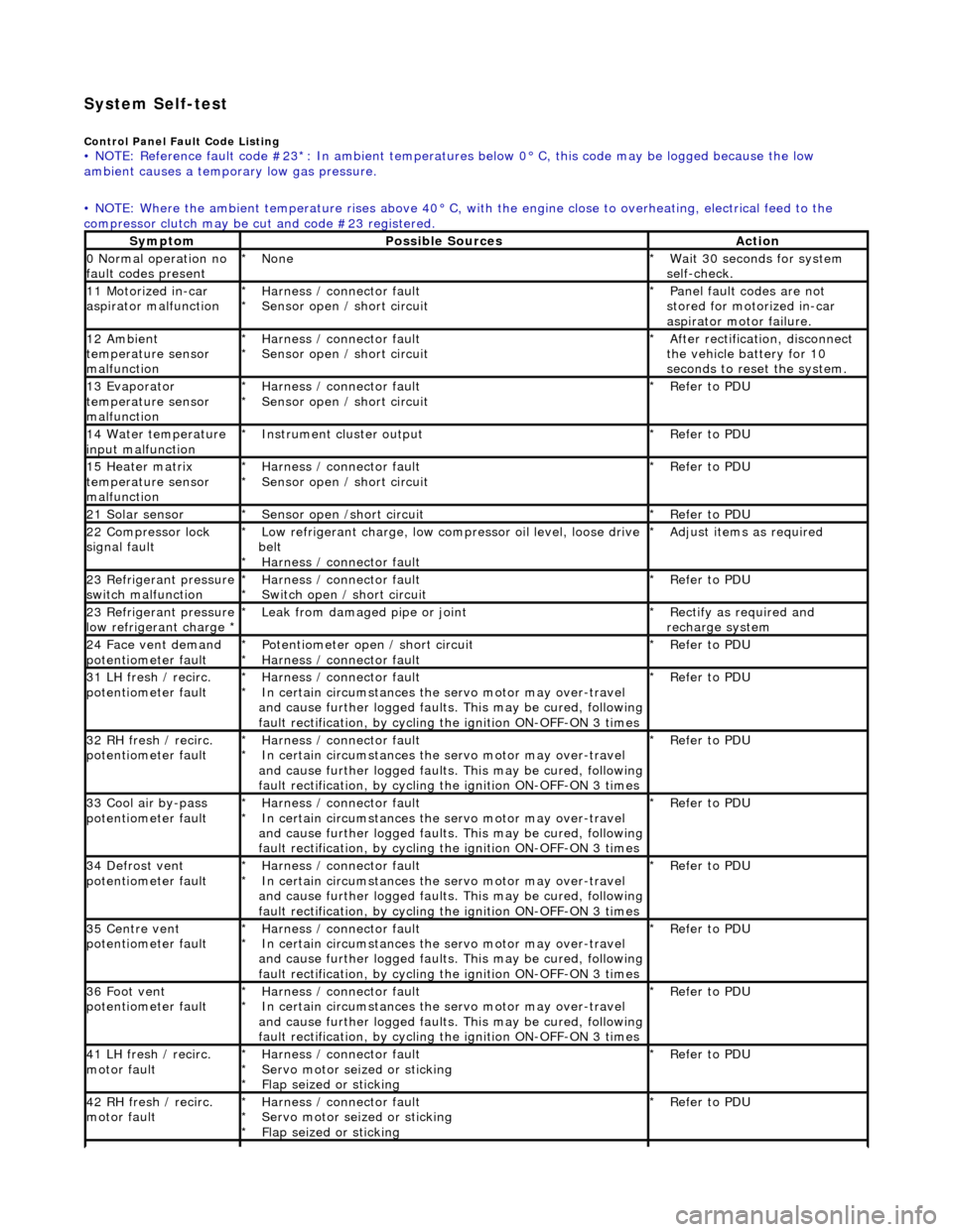
Control Panel Fault Code Listing • NOTE: Reference fault code #23*: In ambient temperatures below 0° C, this code may be logged because the low
ambient causes a tempor ary low gas pressure.
• NOTE: Where the ambient temperature rises above 40° C, with the engine close to overheating, electrical feed to the
compressor clutch may be cut and code #23 registered.
SymptomPossible SourcesAction
0 Normal operation no
fault codes presentNone
*Wait 30 seconds for system
self-check.
*
11 Motorized in-car
aspirator malfunctionHarness / connector fault
Sensor open / short circuit
*
*Panel fault codes are not
stored for motorized in-car
aspirator motor failure.
*
12 Ambient
temperature sensor
malfunctionHarness / connector fault
Sensor open / short circuit
*
*After rectification, disconnect
the vehicle battery for 10
seconds to reset the system.
*
13 Evaporator
temperature sensor
malfunctionHarness / connector fault
Sensor open / short circuit
*
*Refer to PDU
*
14 Water temperature
input malfunctionInstrument cl uster output
*Refer to PDU
*
15 Heater matrix
temperature sensor
malfunctionHarness / connector fault
Sensor open / short circuit
*
*Refer to PDU
*
21 Solar sensorSensor open /short circuit
*Refer to PDU
*
22 Compressor lock
signal faultLow refrigerant charge, low compressor oil level, loose drive
belt Harness / connector fault
*
*Adjust items as required
*
23 Refrigerant pressure
switch malfunctionHarness / connector fault
Switch open / short circuit
*
*Refer to PDU
*
23 Refrigerant pressure
low refrigerant charge * Leak from damaged pipe or joint
*Rectify as required and
recharge system
*
24 Face vent demand
potentiometer faultPotentiometer open / short circuit
Harness / connector fault
*
*Refer to PDU
*
31 LH fresh / recirc.
potentiometer faultHarness / connector fault
In certain circumstances the servo motor may over-travel
and cause further logged faults. This may be cured, following
fault rectification, by cycling the ignition ON-OFF-ON 3 times
*
*Refer to PDU
*
32 RH fresh / recirc.
potentiometer faultHarness / connector fault
In certain circumstances the servo motor may over-travel
and cause further logged faults. This may be cured, following
fault rectification, by cycling the ignition ON-OFF-ON 3 times
*
*Refer to PDU
*
33 Cool air by-pass
potentiometer faultHarness / connector fault
In certain circumstances the servo motor may over-travel
and cause further logged faults. This may be cured, following
fault rectification, by cycling the ignition ON-OFF-ON 3 times
*
*Refer to PDU
*
34 Defrost vent
potentiometer faultHarness / connector fault
In certain circumstances the servo motor may over-travel
and cause further logged faults. This may be cured, following
fault rectification, by cycling the ignition ON-OFF-ON 3 times
*
*Refer to PDU
*
35 Centre vent
potentiometer faultHarness / connector fault
In certain circumstances the servo motor may over-travel
and cause further logged faults. This may be cured, following
fault rectification, by cycling the ignition ON-OFF-ON 3 times
*
*Refer to PDU
*
36 Foot vent
potentiometer faultHarness / connector fault
In certain circumstances the servo motor may over-travel
and cause further logged faults. This may be cured, following
fault rectification, by cycling the ignition ON-OFF-ON 3 times
*
*Refer to PDU
*
41 LH fresh / recirc.
motor faultHarness / connector fault
Servo motor seized or sticking
Flap seized or sticking
*
*
*Refer to PDU
*
42 RH fresh / recirc.
motor faultHarness / connector fault
Servo motor seized or sticking
Flap seized or sticking
*
*
*Refer to PDU
*
Page 1838 of 2490
System Self-test
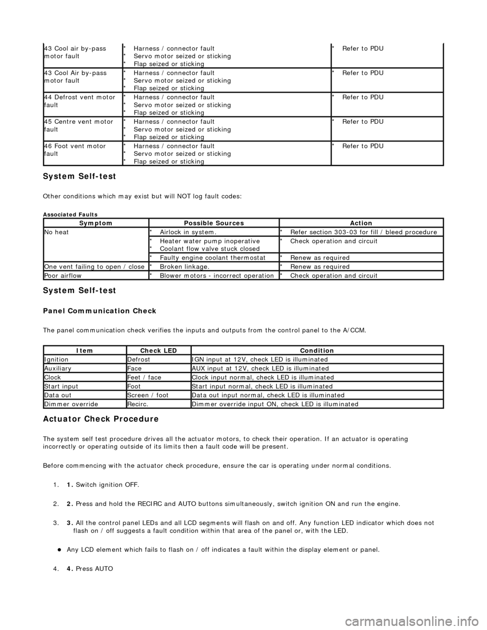
Other conditions which may exist but will NOT log fault codes:
Associated Faults
System Self-test
Panel Communication Check
The panel communication check veri fies the inputs and outputs from the control panel to the A/CCM.
Actuator Check Procedure
The system self test procedure drives all the actuator moto rs, to check their operation. If an actuator is operating
incorrectly or operating outside of its limi ts then a fault code will be present.
Before commencing with the actuator check procedure, ensure the ca r is operating under normal conditions.
1. 1. Switch ignition OFF.
2. 2. Press and hold the RECIRC and AUTO buttons simult aneously, switch ignition ON and run the engine.
3. 3. All the control panel LEDs and all LCD segments will flas h on and off. Any function LED indicator which does not
flash on / off suggests a fault condition within that area of the panel or, with the LED.
Any LCD element which fails to flash on / off indicates a fault within the display element or panel.
4. 4. Press AUTO
43 Cool air by-pass
motor faultHarness / connector fault
Servo motor seized or sticking
Flap seized or sticking
*
*
*Refer to PDU
*
43 Cool Air by-pass
motor faultHarness / connector fault
Servo motor seized or sticking
Flap seized or sticking
*
*
*Refer to PDU
*
44 Defrost vent motor
faultHarness / connector fault
Servo motor seized or sticking
Flap seized or sticking
*
*
*Refer to PDU
*
45 Centre vent motor
faultHarness / connector fault
Servo motor seized or sticking
Flap seized or sticking
*
*
*Refer to PDU
*
46 Foot vent motor
faultHarness / connector fault
Servo motor seized or sticking
Flap seized or sticking
*
*
*Refer to PDU
*
SymptomPossible SourcesAction
No heatAirlock in system.
*Refer section 303-03 for fill / bleed procedure
*
Heater water pump inoperative
Coolant flow valve stuck closed
*
*Check operation and circuit
*
Faulty engine coolant thermostat
*Renew as required
*
One vent failing to open / closeBroken linkage.
*Renew as required
*
Poor airflowBlower motors - incorrect operation
*Check operation and circuit
*
ItemCheck LEDCondition
IgnitionDefrostIGN input at 12V, check LED is illuminated
AuxiliaryFaceAUX input at 12V, check LED is illuminated
ClockFeet / faceClock input normal, check LED is illuminated
Start inputFootStart input normal, check LED is illuminated
Data outScreen / footData out input normal, check LED is illuminated
Dimmer overrideRecirc.Dimmer override input ON, check LED is illuminated
Page 1861 of 2490
Clock - Clock
Description and Operation
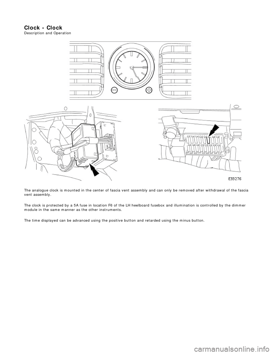
The analogue clock is mounted in the center of fascia vent assembly and can only be removed after withdrawal of the fascia
vent assembly.
The clock is protected by a 5A fuse in lo cation F6 of the LH heelboard fusebox and illumination is controlled by the dimmer
module in the same manner as the other instruments.
The time displayed can be advanced using the positive button and retarded using the minus button.
Page 1862 of 2490
Clock - Clock
Diagnosis and Testing
Tests Using the Portable Diagnostic Unit
Refer to PDU User Guide
The complexity of the electronics involved with the various Electronic Control Modules and the two multiplexed
communication networks, preclude the use of workshop general electrical test equipment. Therefore, reference should be
made to the PDU User Guide for detailed in structions on testing the clock circuit.
The PDU systematically tests an d analyses the clock and the electrucal connections to it.
Where a fault involving the clock is indicated by the PDU, befo re replacing the clock, some basic diagnostic methods may be
necessary to confirm that connections are good and that wiring is not damaged.