Page 1956 of 2490
Installation
1. Install bulb in holder.
2. Install bulb and bulb holder in lamp assembly and rotate 1/4
turn clockwise to seat and retain.
3. Position lamp at bumper ap erture and connect harness
connector.
4. Engage front end tang in bumper aperture.
5. Pivot lamp assembly and firmly seat rear retaining clip in
bumper aperture.
Page 1957 of 2490
Exterior Lighting - Side Lamp Bulb
Removal and Installation
Removal
Installation
1.
Open hood and install fender cover.
2. Rotate bulb holder 1/4 turn counter-clockwise and remove
from headlamp
3. Position bulb holder and harne ss for access and withdraw bulb
from holder.
1. Install parking/sidelamp bulb in bulb holder
2. Position bulb and holder in headlamp, and rotate 1/4 turn
clockwise to fully seat.
3. Remove fender cover and close hood.
Page 1960 of 2490
Exterior Lighting - Side Turn Signal Lamp Bulb
Removal and Installation
Removal
Installation
1.
Remove indicator repeater lamp assembly. Refer to 86.41.41.
2. Remove lamp. Refer to this section.
Twist bulb holder anti-clockwise and remove.
Remove bulb and replace with new one of correct type.
1. Installation is reverse of removal.
Page 1964 of 2490

Interior Lighting - Interior Lighting
Diagnosis and Testing
Tests Using the Portable Diagnostic Unit
Refer to PDU User Guide
The complexity of the electronics involved with the various Electronic Control Modules and the multiplexed communication
networks, preclude the use of workshop general electrical test equipment. Therefore, reference should be made to the PDU
User Guide for detailed inst ructions on testing the interior lamps and circuits.
The PDU systematically tests and analyses the lamp assemblies, the bulbs and the electrical connections to them. It should
be noted that the lamps are not wired directly to the switches.
The lamps are controlled directly by the Bo dy Processor (it has a sufficient number of high power output stages to drive the
lamps / relays compared to other module s) except for the door guard / puddle lamps and the rear passenger reading lamps.
The Body Processor Module receives messages on the SCP network from the door modules relating to door ajar / closed /
locked status, sensed by the door courtesy switch(es).
Where a fault involving a lamp is indicated by the PDU, be fore replacing suspect components, some basic diagnostic
methods may be necessary to confirm that connecti ons are good and that wiring is not damaged.
Page 1976 of 2490

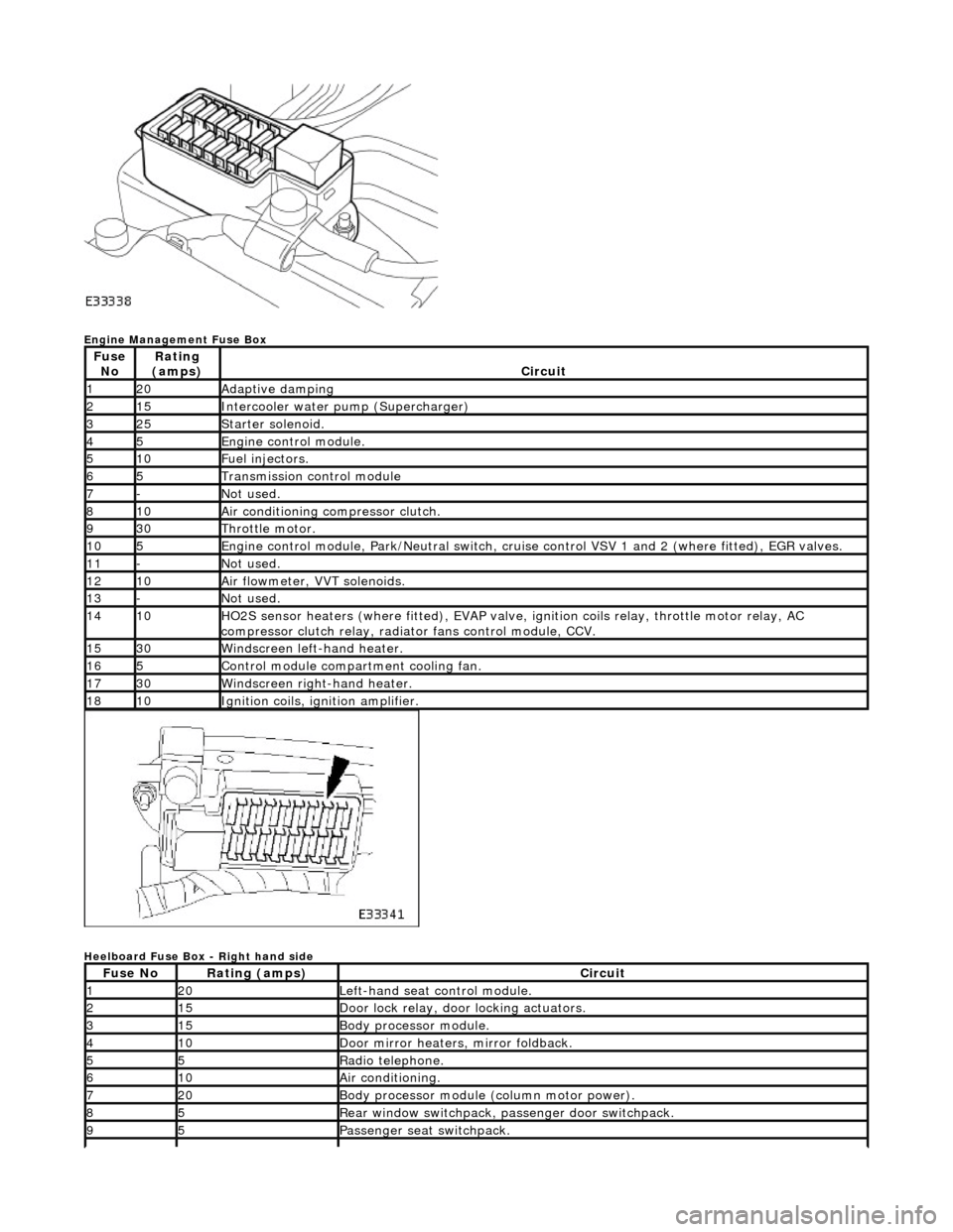
Engine Management Fuse Box
Heelboard Fuse Box - Right hand side
Fuse NoRating
(amps)Circuit
120Adaptive damping
215Intercooler water pump (Supercharger)
325Starter solenoid.
45Engine control module.
510Fuel injectors.
65Transmission control module
7-Not used.
810Air conditioning compressor clutch.
930Throttle motor.
105Engine control module, Park/Neutr al switch, cruise control VSV 1 and 2 (where fitted), EGR valves.
11-Not used.
1210Air flowmeter, VVT solenoids.
13-Not used.
1410HO2S sensor heaters (where fitted ), EVAP valve, ignition coils relay, throttle motor relay, AC
compressor clutch relay, radi ator fans control module, CCV.
1530Windscreen left-hand heater.
165Control module compartment cooling fan.
1730Windscreen right-hand heater.
1810Ignition coils, ignition amplifier.
Fuse NoRating (amps)Circuit
120Left-hand seat control module.
215Door lock relay, door locking actuators.
315Body processor module.
410Door mirror heaters, mirror foldback.
55Radio telephone.
610Air conditioning.
720Body processor module (column motor power).
85Rear window switchpack, passenger door switchpack.
95Passenger seat switchpack.
Page 1978 of 2490

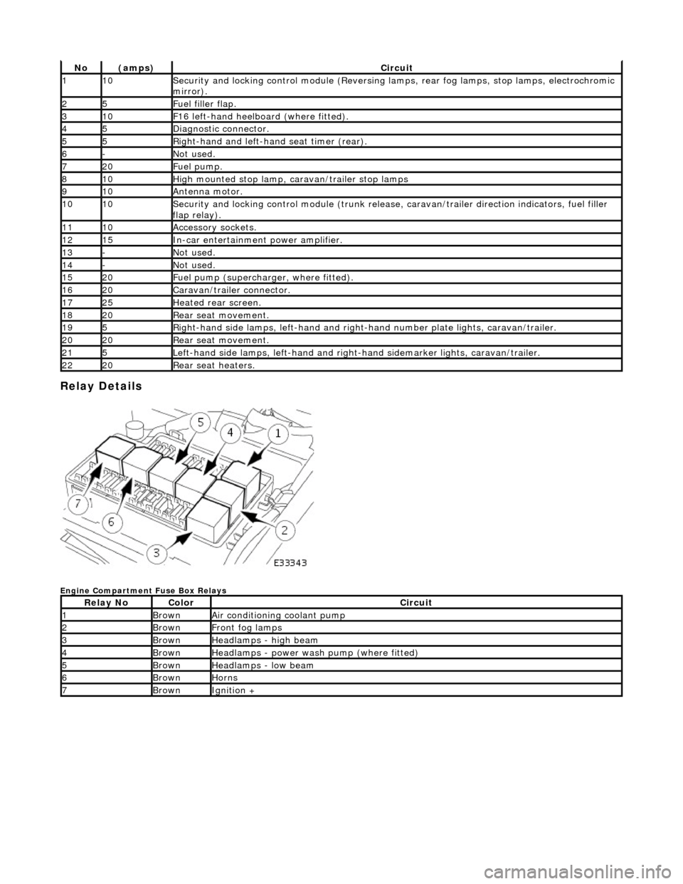
Relay Details
Engine Compartment Fuse Box Relays
No(amps)Circuit
110Security and locking control module (Reversing lamps, rear fog lamps, stop lamps, electrochromic
mirror).
25Fuel filler flap.
310F16 left-hand heelboard (where fitted).
45Diagnostic connector.
55Right-hand and left-han d seat timer (rear).
6-Not used.
720Fuel pump.
810High mounted stop lamp, caravan/trailer stop lamps
910Antenna motor.
1010Security and locking control module (trunk release, caravan/trailer direction indicators, fuel filler
flap relay).
1110Accessory sockets.
1215In-car entertainment power amplifier.
13-Not used.
14-Not used.
1520Fuel pump (supercharger, where fitted).
1620Caravan/trailer connector.
1725Heated rear screen.
1820Rear seat movement.
195Right-hand side lamps, left-h and and right-hand number pl ate lights, caravan/trailer.
2020Rear seat movement.
215Left-hand side lamps, left-hand and right-hand sidemarker lights, caravan/trailer.
2220Rear seat heaters.
Relay NoColorCircuit
1BrownAir conditioning coolant pump
2BrownFront fog lamps
3BrownHeadlamps - high beam
4BrownHeadlamps - power wash pump (where fitted)
5BrownHeadlamps - low beam
6BrownHorns
7BrownIgnition +
Page 1980 of 2490
Front Firewall Relays
Heelboard Fuse Box Relays - Right hand side
* not illustrated
Heelboard Fuse Box Relays - Left hand side
Relay NoColorCircuit
1BlackWindshield RH heater (where fitted)
2BlackWindshield LH heater (where fitted)
Relay NoColorCircuit
1BlueDoor mirror heater
2BlueAir conditioning RH blower
3BlueLeft rear seat lumbar deflate (where fitted) *
4BrownAuxiliary +
5BlueAir conditioning LH blower
Relay NoColorCircuit
1BrownIgnition +
2VioletDoor mirror fold flat (where fitted)
3VioletAir conditioning isolate
4VioletDoor locks
Page 1981 of 2490
Trunk Fuse Box Relays
5VioletDoor mirror fold out (where fitted)
Relay NoColorCircuit
1BrownSecond fuel pump (SC models only)
2BrownRear window defroster
3BrownSide marker, license plate and trailer rear lamps
4BrownFuel pump
5BrownStop lamps (HMSL and trailer only)
6VioletAccessory socket (where fitted)
7VioletFuel filler flap lock
8VioletFuel filler flap unlock