1998 JAGUAR X308 differential
[x] Cancel search: differentialPage 4 of 2490

Stabilizer Bar Mount i
ng
Frame (64.25.12)
Stabilizer Bar Mounting Frame Bushing (64.25.13)
Rear Wheel Bearing (64.15.14)
Wheel Hub Seal (64.15.15)
Wheel Knuckle Bushing (64.15.24)
204‐04: Wheels and Tires
Specification
Description and Operation
Wheels and Tires
Diagnosis and Testing
Wheels and Tires
Removal and Installation
Whee
l and Tire (74.20.05)
204‐05: Vehicle Dynamic Suspension
Description and Operation
Vehicle Dynamic Suspension
Diagnosis and Testing
Vehicle Dynamic Suspension
205: Driveline
205‐00: Driveline System ‐ General Information
Description and Operation
Driveline System
205‐01: Driveshaft
Specification
Description and Operation
Drives
haft
Removal and Installation
Driveshaft (47.15.01)
205‐02: Rear Drive Axle/Differential
Specification
Description and Operation
Page 5 of 2490

Rear Drive Axle and Diffe rential
General Procedures
Differential Output Shaft End Float Check (51.10.24)
In‐Vehicle Repair
Axle Shaft (47.10.01)
Differential Output Shaft Bearing (51.10.22)
Drive Pinion Flange and Drive Pinion Seal (51.20.01)
Removal and Installation
Axle Assembly (51.25.13)
206: Brake System
206‐00: Brake System ‐ Gen
eral Information
Specification
Description and Operation
Brake System
Diagnosis and Testing
Brake System
General Procedures
Brake System Bleeding (70.25.03) ‐ Vehicles With: Standard Brakes
Brake System Bleeding (70.25.03) ‐ Vehicles With: High Performance Brakes
Front Brake Disc Runout Check ‐ Vehicles With: Standard Brakes
Front Brake Disc Runout Chec
k ‐ Vehicles With: High Performance Brakes
Rear Brake Disc Runout Check (70.12.36) ‐ Vehicles With: Standard Brakes
Rear Brake Disc Runout Check (70.12.36) ‐ Vehicles With: High Performance
Brakes
206‐03: Front Disc Brake
Specification
Description and Operation
Front Disc Brake
Removal and Installation
Brake Caliper (70.55.02) ‐ Vehicles With: Standard Brakes
Brake Caliper (70.55.02) ‐ Vehicles With: High Perfo
rmance Brakes
Brake Disc (70.10.10) ‐ Vehicles With: Standard Brakes
Brake Disc (70.10.10) ‐ Vehicles With: High Performance Brakes
Brake Pads (70.40.02) ‐ Vehicles With: Standard Brakes
Page 43 of 2490

Safety Standard
Canister PurgeCANPControls pu
rging of the EVAP canister
Carbon dioxideCO2Colorless gas with
a density of a
pproximately 1.5 ti mes that of air
Carbon mon
oxide
COPoi
sonous gas produced as the re
sult of incomplete combustion
Case G
round
CSE GNDControl modu
le casing ground
Catal
ytic converter
In
-line exhaust system device used to reduce the level of engine exhaust
emissions
Ce
lsius
CSI ter
m for the Centigrade scale, with
freezing point at zero and boiling point
at 100°
Central
Processor Unit
CPUTh
e section of a computer that contai
ns the arithmetic, logic and control
circuits. It performs arithm etic operations, controls instruction processing, and
provides timing signals and other housekeeping operations
Cl
osed Loop
CL
Cl
osed Loop System
CLSControl
system with one
or more feedback loops
Col
umn/Mirror Control
Module
C/MC
M
Control ModuleCMA
self-contained group of electrical/electronic components, designed as a
single replaceable un it, and controlling one or more processes
Controll
er Area Network
CANA
communication system which allows control modules to be linked together
in a network.
Crankshaft Posi
tion
Sensor
CKPSGenerates crankshaft positi on informa
tion in conjunct
ion with the CKPTR (also
generates speed information in certain applications)
Crankshaft Posi
tion
Timing Ring
CKPT
R
Toothe
d ring which
triggers the CKPS
Crankcase Ventila
tion
System
CVSys
tem which scavenges camshaft cover and crankcase emissions and feeds
them into the inlet manifold
Cubic ce nt
imeter
cm
3
Curb weightWe
ight of vehicle with fuel, lubrican
ts and coolant, but excluding driver,
passengers or payload
D
Dat
a Link Connector
DLCConne
ctor providing access and/or control of the vehicle information,
operating conditions, and diagnostic information
De
gree
deg, °Angle or tempe
rature
D
epartment of
Transportation (US)
DO
T
D
epartment of Transport
(UK)
DTp
De
utsche In
stitut für
Normung
DINGerman stand
ards regulation body
Di
agnostic Module
DMSuppl
emental Restraint System (non-c
ontrolling) module for diagnostics
overview
Di
agnostic Test Mode
DTMA le
vel of capability in an OBD system.
May include different functional states
to observe signals, a base level to re ad DTCs, a monitor level which includes
information on signal levels, bi-directional control with on /off board aids, and
the ability to interface with remote diagnosis
Diagnostic Trouble CodeDTCAn al
pha/numeric identifier for a fault
condition identified by the On-Board
Diagnostic (OBD) system
D
ial test indicator
DTIA mechan
ical measuring
instrument, with a rotary indicating pointer
connected to a linear operating probe
D
ifferential pressure
Pressure di
fference betwee
n two regions e.g. between intake manifold and
atmospheric pressures
D
ifferential Pressure
Feedback EGR
DP
FE
An
EGR system that monito
rs differential EGR pressure across a remote orifice
to control EGR flow
D
irect current
dcCurrent which f
lows in on
e direction only, though it may have appreciable
pulsations in its magnitude
Du
al linear switch
DLSJ
-gate switch connected to the TCM on SC vehicles
E
EGR
Temperature EGRT
Sensor
EGRTSens
ing EGR function based on temperature change
EGR Vacu
um Regulator
EVRControls EGR
flow by changi
ng vacuum to the EGR valve
EGR Valve
Position
EVPAn EGR
system that direct
ly monitors EGR valve position to control EGR flow
Electrically E
rasable
Programmable Read-Only
Memory
EEP
ROM
Page 167 of 2490

Rear
Suspension - Rear Suspension
Description an
d Operation
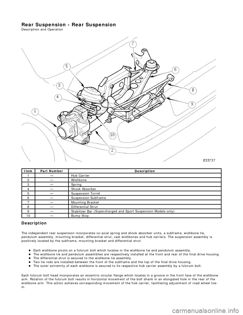
Description
The i
ndependent rear suspension incorporates co-axial sp
ring and shock absorber units, a subframe, wishbone tie,
pendulum assembly, mounting brac ket, differential strut, cast wishbones and hub carriers. The suspension assembly is
positively located by the subframe, mounting bracket and differential strut.
Each wi
shbone pivots on a fulcru
m bolt which locates in the wishbone tie and pendulum assembly.
The wish
bone tie and pendulum assemblies are respectively in
stalled at the front and rear of the final drive housing.
The differential
strut is secured to the wishbone tie assembly.
Two ti
e rods are installed between the front of the
subframe and the top of the final drive housing.
The ou
ter extremity of each wishbone
is secured to its respective hub carrier assembly by a fulcrum bolt.
Each fulcrum bolt head incorporates an ec centric circular flange which locates in a groove in the front face of the wishbone
arm. Rotation of the fulcrum bolt results in horizontal movement of the bolt shank in an elongated hole in the rear of the
wishbone arm. This acti on achieves corresponding movement of the hub carrier, facilita ting adjustment of road wheel toe-
in.
It
em
Par
t Number
De
scription
1—Hub Carrier
2—Wi
shbone
3—Sprin
g
4—Shock Absorber
5—Suspensi
on Turret
6—Suspensi
on Subframe
7—Moun
ting Bracket
8—D
ifferential Strut
9—Stabilizer Ba
r (Supercharged and
Sport Suspension Models only)
10—Bum
p Stop
Page 173 of 2490

10
.
Withdraw the left-hand parking brake cable through the
equalizer.
11
.
Mark the position of the drive shaft coupling to the flexible
coupling.
12
.
Remove the drive shaft from the differential drive coupling.
R
emove the drive shaft to differential drive coupling bolts.
Carefully with
draw and lower the drive shaft from the
differential coupling.
13. CAUTION: Position a suitable piece of wood between the
jack and the rear suspension and axle assembly. Failure to follow
this instruction may result in damage to the vehicle.
Support the rear suspension and axle assembly.
Posi
tion a trolley jack under the rear suspension and axle
assembly.
Page 174 of 2490

Position a suitable piece o
f wood between the jack and the
rear suspension and axle assembly.
Rai s
e the jack to take the weight of the rear suspension
and axle assembly.
14 . NOTE
: Left-hand shown, right-hand similar
Remove the exhaust mounting to suspension bracket bolts.
15 . NOTE
: Right-hand shown, left-hand similar
Remove and discard the subframe front mounting brackets to
body bolts.
16 . NOTE
: Right-hand shown, left-hand similar
Remove the subframe front mounting brackets.
Remove an d discard the mount
ing bracket to subframe
bolts.
R e
move the front mounting bracket.
17. NOTE: Left-hand shown, right-hand similar
Remove differential strut upper mounting to body bracket
securing bolts.
Page 282 of 2490

Driveshaft - Driveshaft
Remo
val and Installation
Remov
a
l
CAUTI
O
N: To preserve 'drive line' refine
ment, individual parts, other than fixings, MUST NOT be renewed. In the event
of any balance or driveshaft component related problem, the complete assembly must be renewed. Under no circumstances
may the flexible (Jurid) coupling be remo ved from the driveshaft (or its fixings be loosened). Do not drop or subject the
driveshaft to damage.
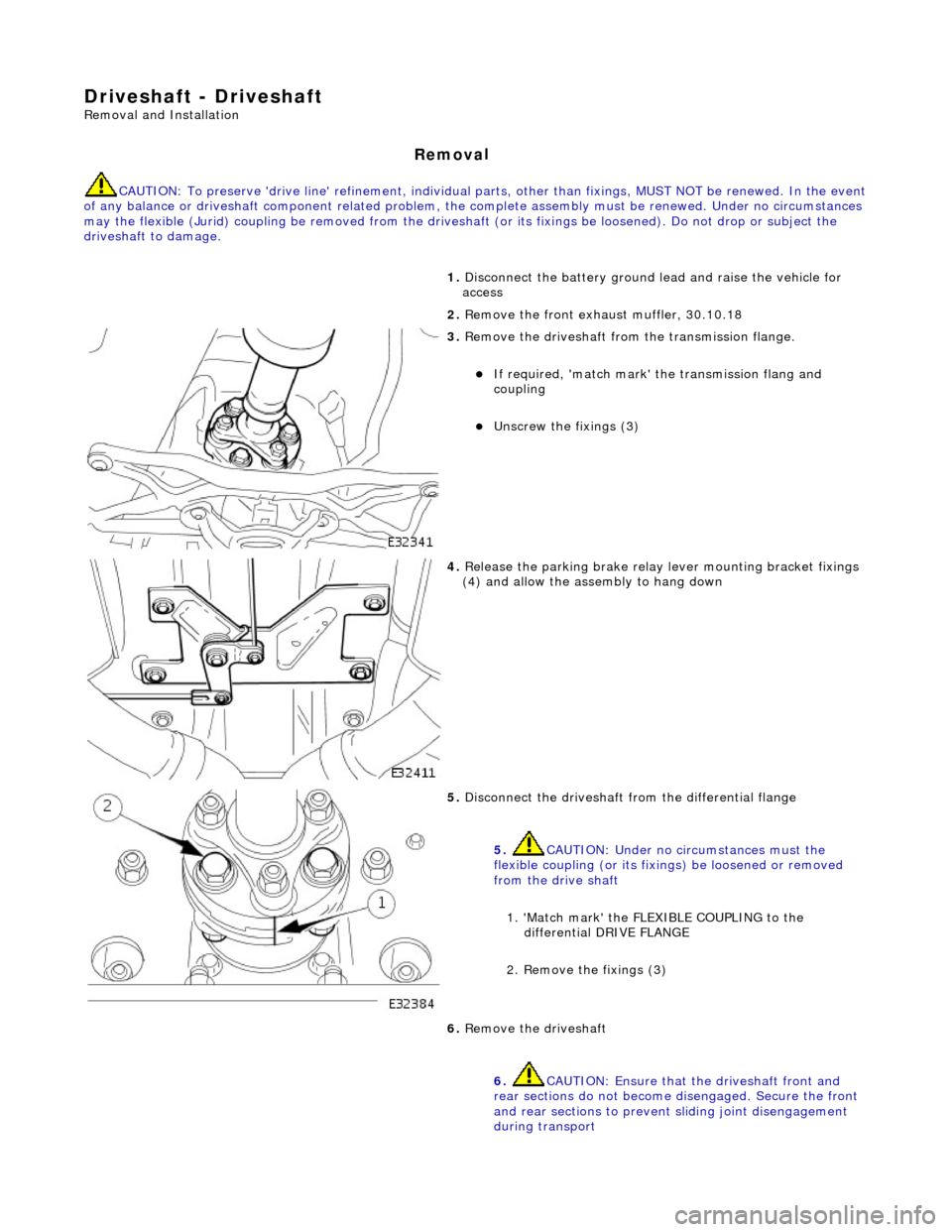
1. Disc
onnect the battery ground
lead and raise the vehicle for
access
2. Remove the front exha ust muffler, 30.10.18
3. Re
move the driveshaft from
the transmission flange.
If required, 'match mark'
the transmissi on flang and
coupling
Unscrew the fi xings (3)
4. Relea s
e the parking brake relay
lever mounting bracket fixings
(4) and allow the assembly to hang down
5. Disc onne
ct the driveshaft fr
om the differential flange
5. CAUTION: Under no circumstances must the
flexible coupling (or its fixings) be loosened or removed
from the drive shaft
1. 'Match mark' the FLEX IBLE COUPLING to the
differential DRIVE FLANGE
2. Remove the fixings (3)
6. Re
move the driveshaft
6. CAUTION: Ensure that the driveshaft front and
rear sections do not become disengaged. Secure the front
and rear sections to preven t sliding joint disengagement
during transport
Page 284 of 2490

Re
ar Drive Axle/Differential -
Lubric
ants, Fluids, Sealants and Adhesives
Capacities
Torques
UnitSp
ecification
F
i
nal Drive
Shell Sp
irax Supe
r TS 90
Hub s
p
line to Axle shaft
Loct
it
e 270 Studlock or equivalent
UnitLi
t
ers
F
i
nal Drive
1,
90
Com p
onent
Nm
B
ol
t - Final drive nose plate
39
- 51
Bol t
- 'A' frame to final drive
9
0 -
110
Nu
t 'A' f
rame to rear mounting bracket
8
5 -
115
Nu
t -
Axle shaft to final drive flange
81
-
99
Nu
t -
Axle shaft to hub
3
04 -
336
N
u
t - Damper lower fixing
8
0 -
100
Bol
t
M12 - Jurid flexible coupling to
transmission and final drive flanges
75 -
88
N
u
t - Lower fulcrum
9
0 -
110
Nu
t -
Pendulum to final drive
1
60 -
200
N
u
t - Stabilizer to wishbone
30
-
40
N
u
t - Tie rod to final drive
8
5 -
105
Nu
t -
Tie rod to wide mounting bracket
8
5 -
115
Nu
t -
Wishbone pivot
8
0 -
100
N
u
t - Wishbone tie to final drive
8
5 -
105
N
u
t 'A' frame to wide mounting bracket
8
5 -
105