Page 488 of 2490

The rotary distri
butor and control sleeve turn relative to ea
ch other, forming the unequal restrictions which create the
differential pressures to operat e the rack piston; the displacement of the di stributor and sleeve being controlled by the
elastic deformation of a torsion bar which is concentric with the pinion and valve. Refer to Positive Center-Feel Torsion Bar
in this sub-sectio n.
The hydraulic reaction piston moves axially, relative to th e rotary distributor, and is connected to the control sleeve by a
three-bearing helical screw. Pressure applied either side of the hydraulic reaction piston is translated into a rotational force
which increases steering effort. For detail s of Servotronic speed-sensitive steering control, refer to Servotronic Control in
this sub-section.
When the vehicle is travelling straight ah ead, the valve restrictions are balanced, thus providing equal pressures on either
side of the rack piston. When load is a pplied at the steering wheel, the two halves of the control valve (rotary distributor
and control sleeve) are displaced making the restrictions unequa l. The resulting differential pressures on either side of the
rack piston, assist the steering rack to mo ve to left or right. As the turning load is removed, the pressures equalize again
and the steering return s to the straight ahead position , aided by suspension geometry.
Serv
otronic Control
P a
rts List
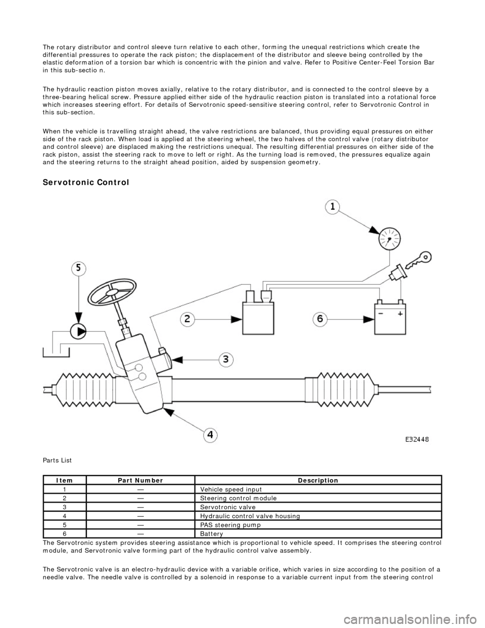
The Servotronic system provides steering assistance which is pr oportional to vehicle speed. It comprises the steering control
module, and Servotronic valve forming part of the hydraulic control valve assembly.
The Servotronic valve is an electro-hydrauli c device with a variable orifice, which varies in size according to the position of a
needle valve. The needle valve is controlled by a solenoid in response to a variable current input from the steering control
Ite
m
Part
Number
Descr
iption
1—Vehi
cl
e speed input
2—Steeri
ng control
module
3—Servotronic valve
4—Hydraulic
control valve housing
5—PAS stee
rin
g pump
6—Batt
ery
Page 1759 of 2490

Sym
ptom #2
Sy
mptom #2
Sym
ptom #3
Sy
mptom #3
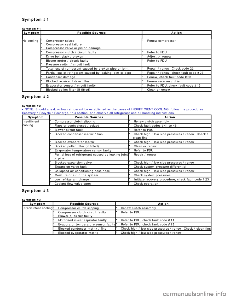
No
cooling
Compressor sei
zed
Compressor seal failure
Compressor valve or piston damage
*
*
*
R
enew compressor
*
Compressor cl
utch / circuit faulty
*
R
efer to PDU
*
D
rive belt slack / broken
*
Adjust or r
enew
*
B
lower motor / circuit faulty
Pressure switch / circuit fault
*
*
R
efer to PDU
*
Total l
oss of refrigerant caused by broken pipe or joint
*
Repair / renew. Check code 2
3
*
P
artial loss of refrigerant caused by leaking joint or pipe
*
R
epair / renew, check fault code #23
*
Conden
ser damage
*
Re
new, check fault code #23
*
Bl
ocked receiver / drier filter
*
R
enew receiver / drier
*
Evaporator senso
r / circuit faulty
*
R
efer to PDU, check fault code #13
*
Bl
ocked pollen filter (if fitted)
*
Cle
an or renew
*
• NOTE: Should a leak or low refrigerant be established as the cause of INSUFFICIENT COOL ING, follow the procedures
Recovery / Recycle / Recharge, this section, and ob serve all refrigerant and oil handling instructions.
Sy
mptom
Possib
le Sources
Acti
on
Insuffi
cient
cooling
Compre
ssor clutch slipping
*
R
enew clutch assembly
*
Fl
aps or vents closed / seized
*
Check f
ault codes #41 to 46
*
Bl
ower circuit fault
*
R
efer to PDU
*
Bl
ocked condenser matrix / fins
*
Check hig
h / low side pr
essures / renew. Check /
clean fins
*
Bl
ocked evaporator matrix
*
Check hig
h / low side
pressures / renew
*
Bl
ocked pollen filter (if fitted)
*
Cle
an or renew
*
Evaporator temp
erat
ure sensor faulty
*
R
efer to PDU
*
P
artial loss of refrigerant caused by leaking joint
or pipe
*
R
epair / renew
*
Blocked expan
sion valve
*
Check hig
h / low side
pressures / renew
*
Expans
ion valve fault
*
Chec
k system pres
sure differential
*
C
ollapsed air conditioning hose hose
*
Check hig
h / low side
pressures / renew
*
Moi
sture or air in the system
*
Chec
k system pressures
*
Low r
efrigerant charge
*
Initiate recovery
procedure, check fault code #23
*
Coo
lant flow valve open
*
Chec
k operation
*
Sy
mptom
Possib
le Sources
Acti
on
Int
ermittent cooling
Compre
ssor clutch slipping
*
R
enew clutch assembly
*
Compressor cl
utch circuit faulty
Blower(s) circuit faulty
*
*
R
efer to PDU
*
Motorized in-car aspirator faulty
*
R
efer to PDU, check fault code #11
*
Evaporator temp
erature sensor faulty
*
R
efer to PDU, check fault code #13
*
Bl
ocked condenser matrix / fins
*
Check hig
h / low side pressures / renew. Check / clean fins
*
Bl
ocked evaporator matrix
*
Check hig
h / low side
pressures / renew
*
Sym
ptom #1
Sy
mptom #1
Sy
mptom
Possib
le Sources
Acti
on
Page 1803 of 2490

Refrigeration Cycle
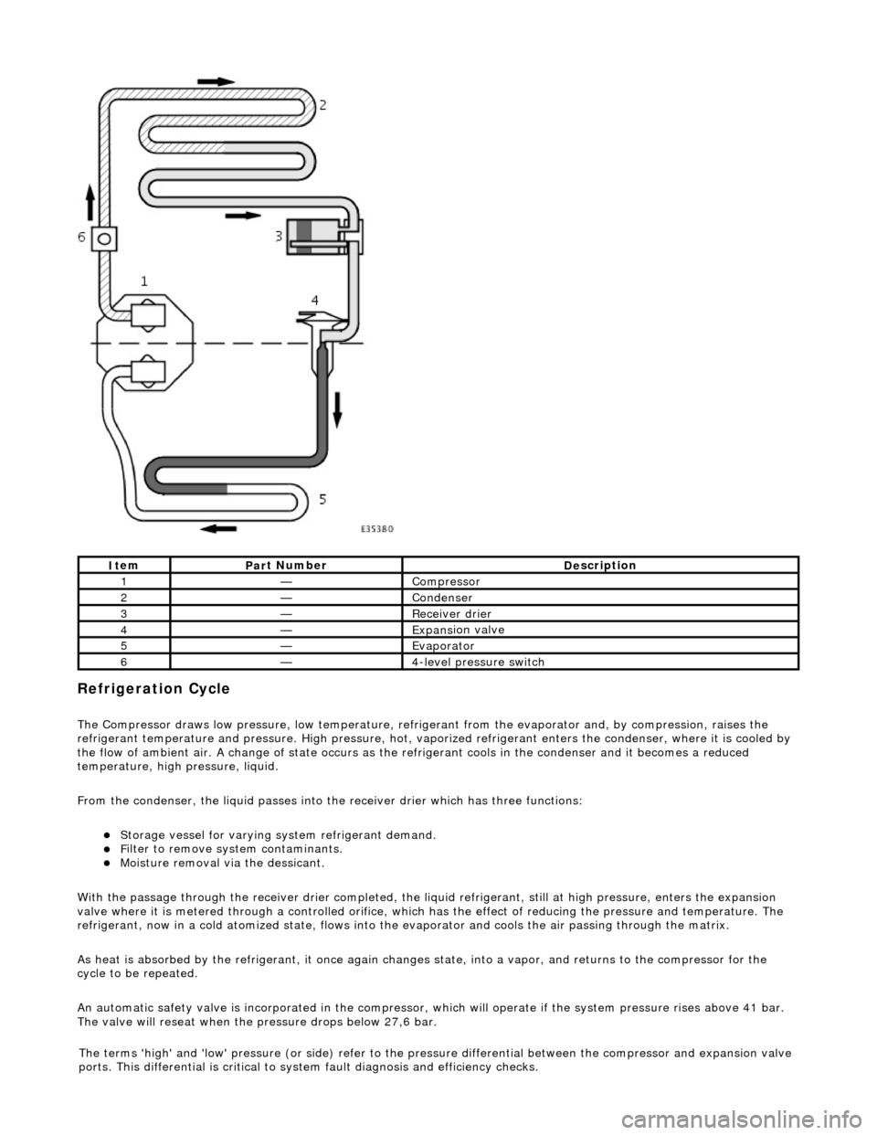
The Compressor draws low pressure, lo
w te
mperature, refrigerant from the evaporat or and, by compression, raises the
refrigerant temperature and pressure. High pressure, hot, vaporized refr igerant enters the condenser, where it is cooled by
the flow of ambient air. A change of state occurs as the refrigerant cools in the condense r and it becomes a reduced
temperature, high pressure, liquid.
From the condenser, the liquid passes into the receiver drier which has three functions:
Storage vessel
for varying sy
stem refrigerant demand.
F
ilter to remove sy
stem contaminants.
Mo
isture removal via the dessicant.
With the passage through the receiver drie r completed, the liquid refrigerant, still at high pressure, enters the expansion
valve where it is metered through a contro lled orifice, which has the effect of reducing the pres sure and temperature. The
refrigerant, now in a cold atomized st ate, flows into the evaporator and cools the air passing through the matrix.
As heat is absorbed by the refrigerant, it once again changes state, into a vapor, and returns to the compressor for the
cycle to be repeated.
An automatic safety valve is incorporated in the compressor, which will operate if the system pressure rises above 41 bar.
The valve will reseat when the pressure drops below 27,6 bar.
It
em
Par
t Number
De
scription
1—Compre
ssor
2—Conden
ser
3—Re
ceiver drier
4—Expans
ion valve
5—Evaporator
6—4
-level pressure switch
The terms 'high' and 'low'
pressure (or si
de) refer to the pres sure differential betw een the compressor and expansion valve
ports. This differential is critical to sy stem fault diagnosis and efficiency checks.
Page 2387 of 2490
Key to Plan
Standard Wheelbase Body Dimensions- Side View
KeyLocation
1Front face body-bumper strut/mounting point
2Rearmost hole, vee-mount to crush tube
3Front Master Datum Plan, centre li ne of front crossmember rear mount ing at main floor RH longitudinal
4Rearmost hole, transmission mounting at main floor RH longitudinal
5Handbrake rear lever bracket fixings
6Rear Master Datum Plan, rear longitudinal
7Tapped boss, rear suspension 'A' frame mounting bush
8Rear suspension spring-pan damper mounting
9Rear suspension differential strut mounting
10Rear face body-bumper strut/mounting point
11Driveshaft centre bearing mounting
Page 2388 of 2490
Key to SideView
Long Wheelbase Body Dimensions-Plan
KeyLocation
1Front face body-bumper strut/mounting point
2Front Master Datum Vertical, centre line of front crossmember rear mounting
3Transmission mountings at the main floor longitudinal
4Handbrake rear lever bracket fixings
5Rear Master Datum Vertical,, rear longitudinal
6Tapped boss, rear suspensi on 'A' frame mounting bush
7Rear suspension spring-pan damper mounting
8Rear suspension differential strut mounting
9Rear face body-bumper strut/mounting point
10Wheel centre to bumper cover face
11Wheelbase
12Wheel Centre to Bumper Cover Face
13Driveshaft centre bearing mounting
Page 2389 of 2490
Key to Plan
Long Wheelbase Body Dimensions- Side View
KeyLocation
1Front face body-bumper strut/mounting point
2Rearmost hole, vee-mount to crush tube
3Front Master Datum Plan, centre line of front crossmember rear mount ing at main floor RH longitudinal
4Rearmost hole, transmission mounting at main floor RH longitudinal
5Handbrake rear lever bracket fixings
6Rear Master Datum Plan, rear longitudinal
7Tapped boss, rear suspension 'A' frame mounting bush
8Rear suspension spring-pan damper mounting
9Rear suspension differential strut mounting
10Rear face body-bumper strut/mounting point
11Driveshaft centre bearing mounting
Page 2390 of 2490
Key to SideView
KeyLocation
1Front face body-bumper strut/mounting point
2Front Master Datum Vertical, centre line of front crossmember rear mounting
3Transmission mountings at the main floor longitudinal
4Handbrake rear lever bracket fixings
5Rear Master Datum Vertical,, rear longitudinal
6Tapped boss, rear suspensi on 'A' frame mounting bush
7Rear suspension spring-pan damper mounting
8Rear suspension differential strut mounting
9Rear face body-bumper strut/mounting point
10Wheel centre to bumper cover face
11Wheelbase
12Wheel Centre to Bumper Cover Face
13Driveshaft centre bearing mounting
Page 2481 of 2490
Uni-Body, Subframe and Mounting System - Rear Axle Crossmember
Removal and Installation
Removal
CAUTION: Replacement of nuts and bolts: Various thread-locking devices are used on nuts and bolts throughout the
vehicle. These devices restrict the number of times a nut or bolt can be used. See section 100-00 for information.
1. Raise vehicle on a four-post li ft. Refer to section 100-02.
2. Remove subframe to differentia l-casing rear bracket bolts.
3. Where fitted, remove bolts se curing fuel vapor pipe to
subframe.
4. Remove subframe to differential bracket front nuts and bolts.
5. Support the differential assembly.
Position a jack under the differential drive coupling.
Position a piece of wood between the jack and the
differential drive coupling.
Raise the jack until the diffe rential is just supported.