Page 2116 of 2490

Rear View Mirrors - Exterior Mirror Glass
Removal and Installation
Removal
CAUTION: If as a result of accidental impact, a powered fold-back mirror is mo ved 'out of position', it must only be re-
positioned by initiating the fold-back sequence as described in this section. No attempt must be made to manually return
the mirror to the normal position. Failure to adopt this procedure will result in vibration of the unlocked mirror head and
consequent loss or distortion of rear vision.
Installation
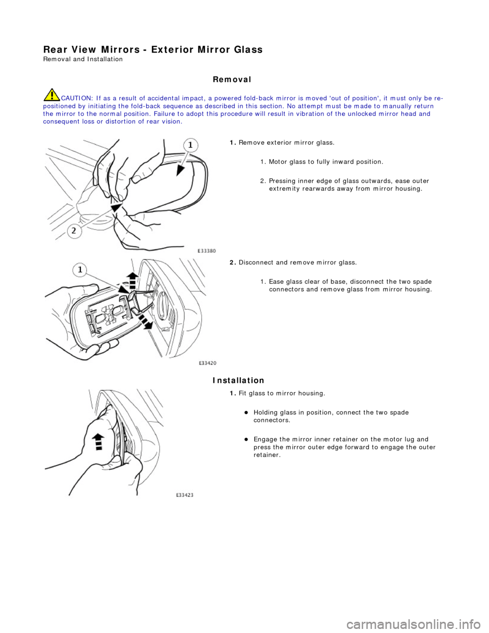
1. Remove exterior mirror glass.
1. Motor glass to fully inward position.
2. Pressing inner edge of glass outwards, ease outer
extremity rearwards away from mirror housing.
2. Disconnect and remove mirror glass.
1. Ease glass clear of base, disconnect the two spade connectors and remove gl ass from mirror housing.
1. Fit glass to mirror housing.
Holding glass in position , connect the two spade
connectors.
Engage the mirror inner retainer on the motor lug and
press the mirror outer edge fo rward to engage the outer
retainer.
Page 2119 of 2490
Rear View Mirrors - Interior Mirror Mounting Block
Removal and Installation
Removal
Installation
1. Remove battery cover and disc onnect ground cable from
battery terminal. Refer to 86.15.19.
2. Position a protective cover over top of facia.
3. Remove roof console for ac cess. Refer to 76.13.69.90.
4. Remove rain sensor unit. Refer to Section 501.16.
5. Remove mirror from mounting block. Refer to 76.10.51 or
76.10.56 (electrochromic).
6. Apply a suitable solvent around edge of mounting block.
7. Commencing at the top and exercising care to avoid windshield
damage, use a thin plastic knife to ease block free.
8. Using a suitable solvent, clean residual adhesive from block
mounting area.
1. Using masking tape, mark block mounting area on windshield.
2. Apply Permabond F Grade 5 Initiator to mounting area of
windshield.
3. Apply a bead of Permabond F246 to bottom and each vertical
side of block over 2/3 of block height.
Page 2120 of 2490
4. Press mounting block onto marked area and hold in position for one minute.
5. After a period of 15 minutes, remove and discard masking
tape.
6. Using a scraper, carefully re move any excess adhesive.
7. NOTE: The following time is the MINIMUM PERIOD required for
adhesive curing. Failure to allow th is period will result in bonding
failure, necessitating repeat of the complete procedure.
After a further period of at le ast 6 hours, install mirror on
mounting block. Refer to 76.10.51 or 76.10.56.
8. Install roof console. Refer to 76.13.69.90.
9. Install rain sensor unit. Refer to Section 501.16.
10. Remove protective cover from facia.
11. Connect ground cable to batter y terminal and install battery
cover. Refer to 86.15.15.
Page 2181 of 2490
Glass, Frames and Mechanisms - Door Window Control Switch Bulb
Removal and Installation
Removal
1. Remove casing/armrest asse mbly from door. Refer to
76.34.01.
2. Slacken and remove armres t front securing screw
3. Position armrest for access, slacken and remove two
switchpack securing screws and remove switchpack assembly from armrest.
4. Invert switchpack and using a small flat bladed screwdriver
rotate bulb holder 1/8 turn counterclockwise.
5. Remove bulb from switchpack base.
Page 2182 of 2490
Installation
1.
Fit illumination bulb in switchpa ck base and using a small flat
bladed screwdriver, rotate it 1/ 8 turn clockwise to fully seat.
2. Fit switchpack to armrest. Refer to 86.25.03.
3. Fit casing/armrest assembly to door. Refer to 76.34.01.
Page 2219 of 2490

Instrument Panel and Console - Instrument Panel and Instrument Panel
Console
Description and Operation
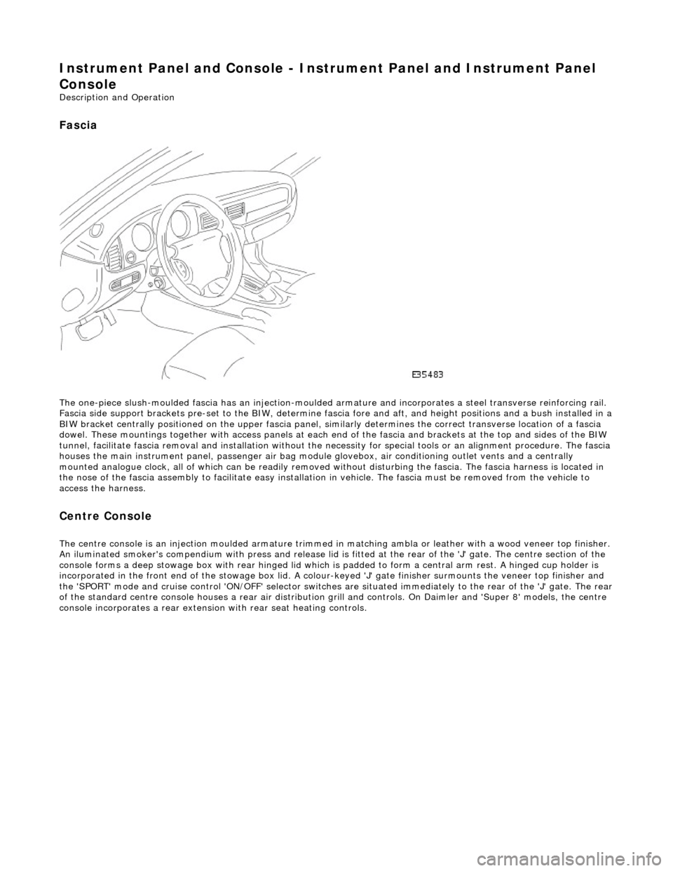
Fascia
The one-piece slush-moulded fascia has an injection-moulded ar mature and incorporates a steel transverse reinforcing rail.
Fascia side support brackets pre-set to th e BIW, determine fascia fore and aft, and height position s and a bush installed in a
BIW bracket centrally positioned on the upper fascia panel, similarly determines the correct transverse location of a fascia
dowel. These mountings together with access panels at each en d of the fascia and brackets at the top and sides of the BIW
tunnel, facilitate fascia removal and instal lation without the necessity for special tools or an alignment procedure. The fasci a
houses the main instrument panel, pass enger air bag module glovebox, air conditioning outlet vents and a centrally
mounted analogue clock, all of which can be readily removed wi thout disturbing the fascia. The fascia harness is located in
the nose of the fascia assembly to facilitate easy installati on in vehicle. The fascia must be removed from the vehicle to
access the harness.
Centre Console
The centre console is an injection moulded armature trimmed in matching ambla or leather with a wood veneer top finisher.
An iluminated smoker's compendium with pr ess and release lid is fitted at the rear of the 'J' gate. The centre section of the
console forms a deep stowage box with rear hinged lid which is padded to form a central arm rest. A hinged cup holder is
incorporated in the front end of the stowage box lid. A colour-keyed 'J' gate finisher surmounts the veneer top finisher and
the 'SPORT' mode and cruise control 'ON/OFF' selector switches are situated immediately to the rear of the 'J' gate. The rear
of the standard centre console houses a re ar air distribution grill and controls. On Daimler and 'Super 8' models, the centre
console incorporates a rear extensio n with rear seat heating controls.
Page 2250 of 2490
56. Partially withdraw airbag module, disconnect link harness
multiplug and remove airbag from facia.
57. Remove RH vent/duct assembly from facia.
Remove two screws securing vent/duct assembly to facia
and remove assembly. Remove and discard securing screw plastic inserts from facia.
58. Carefully withdraw centre vent veneer panel.
59. Remove four screws securing centre vent to facia.
60. Remove centre vent.
Withdraw centre vent for access, disconnect clock harness
multiplug and remove vent.
Remove and discard centre ve nt retaining screw plastic
inserts from facia.
Page 2251 of 2490
Remove clock from centre vent.
61. Reposition facia face down on bench.
62. Withdraw centre defro st vent for access, release solar sensor
harness multiplug from retaining cl ip and disconnect multiplug.
63. Remove centre defrost vent co mplete with solar sensor, and
remove vent retaining clips from facia.
64. Carefully remove left and righ t hand defrost vents from facia
and remove vent retaining clips from facia.
65. Carefully remove left and righ t hand top vents from facia.