Page 1502 of 2490

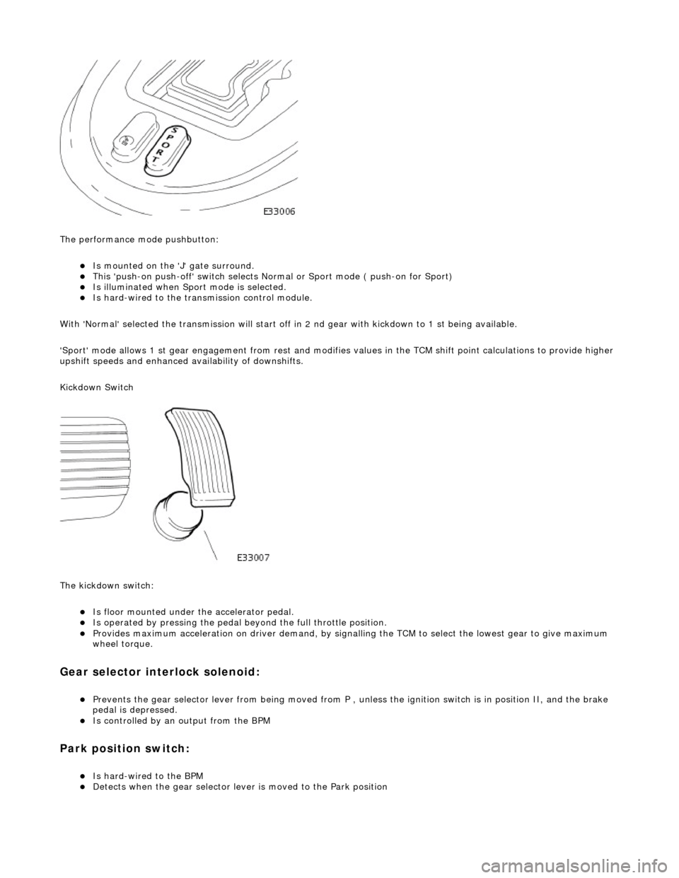
The performance mode pushbutton:
Is mounted on the 'J' gate surround. This 'push-on push-off' swit ch selects Normal or Sport mode ( push-on for Sport) Is illuminated when Sport mode is selected. Is hard-wired to the transmission control module.
With 'Normal' selected the transmissi on will start off in 2 nd gear with kickdown to 1 st being available.
'Sport' mode allows 1 st gear en gagement from rest and modifies values in the TCM shift point calculations to provide higher
upshift speeds and enhanced availability of downshifts.
Kickdown Switch
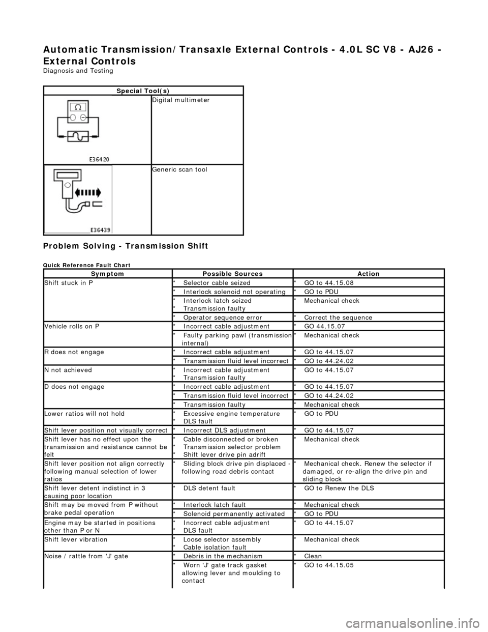
The kickdown switch:
Is floor mounted under th e accelerator pedal. Is operated by pressing the pedal beyond the full throttle position. Provides maximum acceleration on driver demand, by signalling the TCM to select the lowest gear to give maximum
wheel torque.
Gear selector interlock solenoid:
Prevents the gear selector lever from being moved from P , unless the ignition switch is in position II, and the brake
pedal is depressed.
Is controlled by an output from the BPM
Park position switch:
Is hard-wired to the BPM Detects when the gear selector lever is moved to the Park position
Page 1504 of 2490

Automatic Transmission/Transaxle External Controls - 4.0L SC V8 - AJ26 -
External Controls
Diagnosis and Testing
Problem Solving - Transmission Shift
Quick Reference Fault Chart
Special Tool(s)
Digital multimeter
Generic scan tool
SymptomPossible SourcesAction
Shift stuck in P Selector cable seized
*GO to 44.15.08
*
Interlock solenoid not operating
*GO to PDU
*
Interlock latch seized
Transmission faulty
*
*Mechanical check
*
Operator sequence error
*Correct the sequence
*
Vehicle rolls on P Incorrect cable adjustment
*GO 44.15.07
*
Faulty parking pawl (transmission internal)
*Mechanical check
*
R does not engageIncorrect cable adjustment
*GO to 44.15.07
*
Transmission fluid level incorrect
*GO to 44.24.02
*
N not achievedIncorrect cable adjustment
Transmission faulty
*
*GO to 44.15.07
*
D does not engageIncorrect cable adjustment *GO to 44.15.07
*
Transmission fluid level incorrect
*GO to 44.24.02
*
Transmission faulty
*Mechanical check
*
Lower ratios will not holdExcessive engine temperature
DLS fault
*
*GO to PDU
*
Shift lever position not visually correctIncorrect DLS adjustment
*GO to 44.15.07
*
Shift lever has no effect upon the
transmission and resistance cannot be
feltCable disconnected or broken
Transmission selector problem
Shift lever drive pin adrift
*
*
*Mechanical check
*
Shift lever position not align correctly
following manual selection of lower
ratiosSliding block drive pin displaced - following road debris contact
*Mechanical check. Renew the selector if
damaged, or re-align the drive pin and
sliding block
*
Shift lever detent indistinct in 3
causing poor locationDLS detent fault
*GO to Renew the DLS
*
Shift may be moved from P without
brake pedal operationInterlock latch fault
*Mechanical check
*
Solenoid permanently activated
*GO to PDU
*
Engine may be started in positions
other than P or N Incorrect cable adjustment
DLS fault
*
*GO to 44.15.07
*
Shift lever vibrationLoose selector assembly
Cable isolation fault
*
*Mechanical check
*
Noise / rattle from 'J' gateDebris in the mechanism
*Clean
*
Worn 'J' gate track gasket
allowing lever and moulding to
contact
*GO to 44.15.05
*
Page 1508 of 2490
Automatic Transmission/Transaxle External Contro ls - 4.0L SC V8 - AJ26 -
Brake Shift Interlock Actuator Manual Override
General Procedures
1. To override the gearshift interlock:
1. Unscrew the release catch blanking plug.
2. Insert the ignition key into the aperture, depress the release catch and simultan eously move the gear
selector lever from the Park position. The lever will
only move approximately 25 mm with the key
inserted.
3. Remove the ignition key and replace the blanking plug.
Page 1510 of 2490

Automatic Transmission/Transaxle External Contro ls - 4.0L SC V8 - AJ26 -
Selector Lever Cable Adjustment
General Procedures
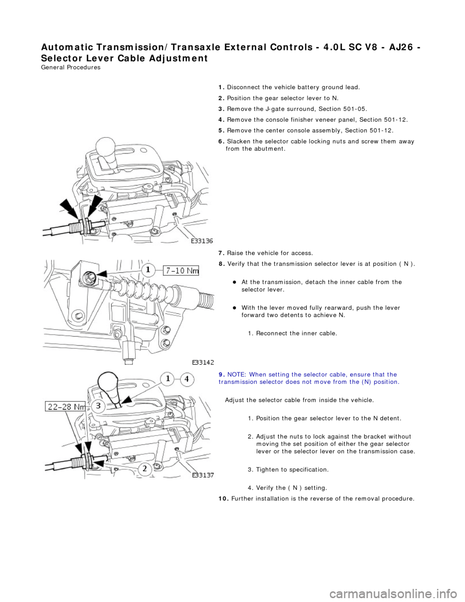
1.
Disconnect the vehicle battery ground lead.
2. Position the gear sele ctor lever to N.
3. Remove the J-gate surround, Section 501-05.
4. Remove the console finisher ve neer panel, Section 501-12.
5. Remove the center console assembly, Section 501-12.
6. Slacken the selector cable lock ing nuts and screw them away
from the abutment.
7. Raise the vehicle for access.
8. Verify that the transmis sion selector lever is at position ( N ).
At the transmission, detach the inner cable from the
selector lever.
With the lever moved fully rearward, push the lever
forward two detents to achieve N.
1. Reconnect the inner cable.
9. NOTE: When setting the selector cable, ensure that the
transmission selector does no t move from the (N) position.
Adjust the selector cable from inside the vehicle. 1. Position the gear select or lever to the N detent.
2. Adjust the nuts to lock against the bracket without moving the set position of either the gear selector
lever or the select or lever on the transmission case.
3. Tighten to specification.
4. Verify the ( N ) setting.
10. Further installation is the reve rse of the removal procedure.
Page 1511 of 2490
Automatic Transmission/Transaxle External Contro ls - 4.0L SC V8 - AJ26 -
Brake Shift Interlock Actuator
Removal and Installation
Removal
Installation
1.
Disconnect the vehicle battery ground lead.
2. Remove the J-gate surround, Section 501-05.
3. Remove the console finisher ve neer panel, Section 501-12.
4. Remove the interlock so lenoid lever cover.
5. Remove the gearshift interlock solenoid.
1. Remove the (2) solenoid nuts.
2. Detach the solenoid from the latch pin.
3. Disconnect the solenoid multiplug.
1. Installation is th e reverse of the re moval procedure.
2. Refer to the illustration.
Page 1512 of 2490
Automatic Transmission/Transaxle External Contro ls - 4.0L SC V8 - AJ26 -
Kickdown Switch
Removal and Installation
Removal
Installation
1. Disconnect the kickdown switch multiplug.
Move the carpet for access.
2. Remove the kickdown switch.
Rotate counter-clockwise.
1. Installation is th e reverse of the re moval procedure.
2. The kickdown switch MUST be adjusted in accordance with
(44.15.38).
Page 1514 of 2490
Installation
2. Slacken the outer cable locknuts.
13. Push the outer cable grommet through the transmission
tunnel aperture.
14. Remove the selector cable assembly from the vehicle.
1. Assemble the cable to the gear shift assembly.
1. Locate the outer cable and fit the inner cable to the gear selector arm. Tighten to the specified torque
figure.
2. Position the abutment nuts to the approximate position, but do not tighten.
2. Fit the cable to the transmission and tighten the fixings to the
specified torque figure.
Page 1518 of 2490

Automatic Transmission/Transaxle External Contro ls - 4.0L SC V8 - AJ26 -
Transmission Control Switch (TCS)
Removal and Installation
Removal
Installation
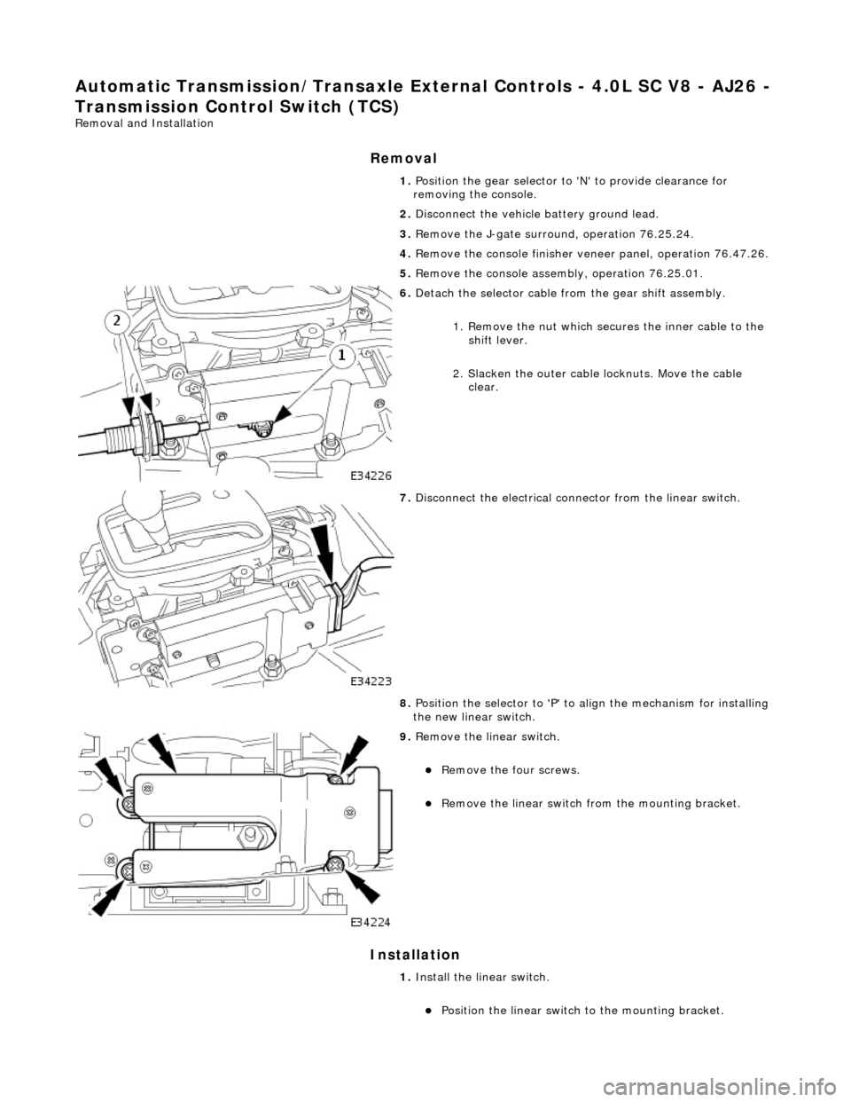
1. Position the gear selector to 'N' to provide clearance for
removing the console.
2. Disconnect the vehicle battery ground lead.
3. Remove the J-gate surroun d, operation 76.25.24.
4. Remove the console finisher vene er panel, operation 76.47.26.
5. Remove the console assembly, operation 76.25.01.
6. Detach the selector cable from the gear shift assembly.
1. Remove the nut which secures the inner cable to the shift lever.
2. Slacken the outer cable locknuts. Move the cable clear.
7. Disconnect the electrical conne ctor from the linear switch.
8. Position the selector to 'P' to align the mechanism for installing
the new linear switch.
9. Remove the linear switch.
Remove the four screws.
Remove the linear switch fro m the mounting bracket.
1. Install the linear switch.
Position the linear switch to the mounting bracket.