Page 1519 of 2490
Align the drive peg and lower sliding block of the switch to
the mating components of the selector mechanism.
2. Install the four screws, bu t do not fully tighten.
Remove the Ty-Strap from the dual linear switch.
Use the manual release and repo sition the selector to 'N'
for installation of the selector cable.
3. Connect the electrical connector to the linear switch.
4. Assemble the cable to the gear shift assembly.
1. Locate the outer cable and fit the inner cable to the gear selector arm. Tighten to 22-28 Nm.
2. Position the abutment nuts to the approximate position, but do not tighten.
5. NOTE: When setting the selector cable, ensure that the
selector lever on the transmission ca sing is still in the 'N' position.
Adjust the selector cable from inside the vehicle.
1. Confirm that the selector lever is in the 'N' position.
2. Adjust the nuts to lock against the bracket without
Page 1521 of 2490
Automatic Transmission/Transaxle External Contro ls - 4.0L SC V8 - AJ26 -
Selector Lever Knob
Removal and Installation
Removal
Installation
1.
Disconnect the vehicle battery ground lead.
2. Remove the select or lever knob.
1. Slacken the ferrule, rotate clockwise.
2. Rotate the knob coun ter-clockwise to remove.
1. Refer to the illustration.
1. Fit the knob.
2. Refer to the illustration.
Page 1693 of 2490
Filler Cap and P
ipe
The fuel
filler cap with bayonet-type fixi
ng is located beneath a remote-release sp ring-latched lid on the rear saddle panel
on the left-hand-side of the vehicle.
Fuel Pum
p
The fu
el pump(s) is energized by an ECM co
ntrolled relay. Fuel is drawn by this pu mp and supplied to the fuel injectors via
the fuel line, filter and fuel rails.
Servicing of the fuel pump re quires fuel tank removal.
Ev
aporative Loss Flange Assembly
The evaporative-loss flan
ge asse
mbly is mounted centrally on top of the tank. The flange assembly consists of a removeable
steel cap which mounts the evaporative emissions system vapor outlet valves and, if applicable, a pressure sensor. The
external electrical supply to th e fuel pump(s) is also made via a connector on the flange.
The flange assembly is fixed to the tank by a locking ring which is turned usin g special tool JD-174. A seal is fitted between
the flange assembly and the tank. Three di fferent flange assemblies are applicable according to the evaporative emission
system fitted to the vehicle. The fl ange size and fixing are identical fo r the three systems, as described.
Removal of the evaporative flange assembly is necessary to gain access to th e fuel pump(s) and other internal components.
To remove the evaporative fl ange assembly the fuel tank must first be removed.
The evaporative flange variant assemblies are described, together with service information, in Section 303-13.
Fuel R
eturn
Excess fuel
is directed back to
the fuel tank via a return line.
Fuel Pum
p Relay
The
fuel pump relay,
under control of the ECM, switches power to the fuel pump motor.
I
nertia Fuel Shutoff (IFS) Switch
The IF
S switch is located in the right-hand
side footwell behind the footboard carpet . When activated the switch isolates the
ignition system and fuel pump, releases any locked doors and disables unnecessary electrical systems. The system can be
reset by pressing down the flexible cover on the top of the switch.
• NOTE: The doors will not unlock if the IFS switch is tripped when the ignition switch is in position '0'.
Page 1694 of 2490
P a
rts List
The fuel level sensor is mounte d on the fuel tank vertical face and reacts to level changes via a float and pivot which is
connected to a potentiometer. As the fuel level drops the resistance increases.
The fuel level sensor can be serviced without removing the tank.
It e
m
Par
t
Number
De
scr
iption
1—Lockin
g rin
g
2—Fue
l
level sensor
3—Seal
Fuel
Level Sensor
Page 1735 of 2490
10
.
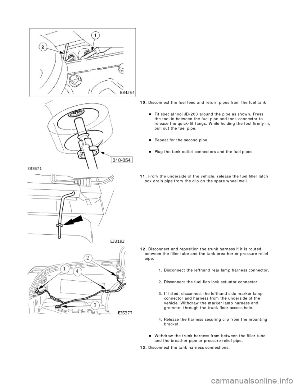
Disconnect the fuel feed and return pipes from the fuel tank
F
it special tool JD-203 around
the pipe as shown. Press
the tool in between the fuel pipe and tank connector to
release the quick-fit tangs. While holding the tool firmly in,
pull out the fuel pipe.
Repeat
for the second pipe.
Plu
g the tank outlet connectors and the fuel pipes.
11
.
From the underside of the vehicl e, release the fuel filler latch
box drain pipe from the clip on the spare wheel well.
12
.
Disconnect and reposition the tr unk harness if it is routed
between the filler tube and the ta nk breather or pressure relief
pipe.
1. Disconnect the lefthand re ar lamp harness connector.
2. Disconnect the fuel flap lock actuator connector.
3. If fitted, disconnect the lefthand side marker lamp
connector and harness fro m the underside of the
vehicle. Withdraw the marker lamp harness and
grommet through the trunk floor access hole.
4. Release the harness securi ng clip from the mounting
bracket.
Wi
thdraw the trunk harness from between the filler tube
and the breather pipe or pressure relief pipe.
13. Disconnect the tank harness connections.
Page 1738 of 2490
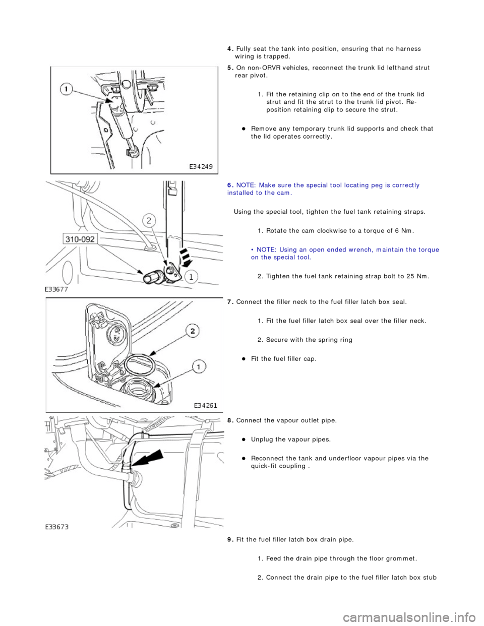
4. Full
y seat the tank into positi
on, ensuring that no harness
wiring is trapped.
5. On non-
ORVR vehicles, reconnec
t the trunk lid lefthand strut
rear pivot.
1. Fit the retaining clip on to the end of the trunk lid strut and fit the strut to the trunk lid pivot. Re-
position retaining clip to secure the strut.
Re
move any temporary trunk lid supports and check that
the lid operates correctly.
6. NOTE
: Make sure the special tool locating peg is correctly
installed to the cam.
Using the special tool, tighten the fuel tank retaining straps.
1. Rotate the cam clockwise to a torque of 6 Nm.
• NOTE: Using an open ended wrench, maintain the torque
on the special tool.
2. Tighten the fuel tank reta ining strap bolt to 25 Nm.
7. Connect the fi
ller neck to the fuel filler latch box seal.
1. Fit the fuel filler latch box seal over the filler neck.
2. Secure with the spring ring
F i
t the fuel filler cap.
8. Connect the vapour outlet pip
e.
Unplug the v
a
pour pipes.
Reconn
ect th
e tank and underfloor vapour pipes via the
quick-fit coupling .
9. Fit the fuel filler latch box drain pipe.
1. Feed the drain pipe th rough the floor grommet.
2. Connect the drain pipe to the fuel filler latch box stub
Page 1739 of 2490
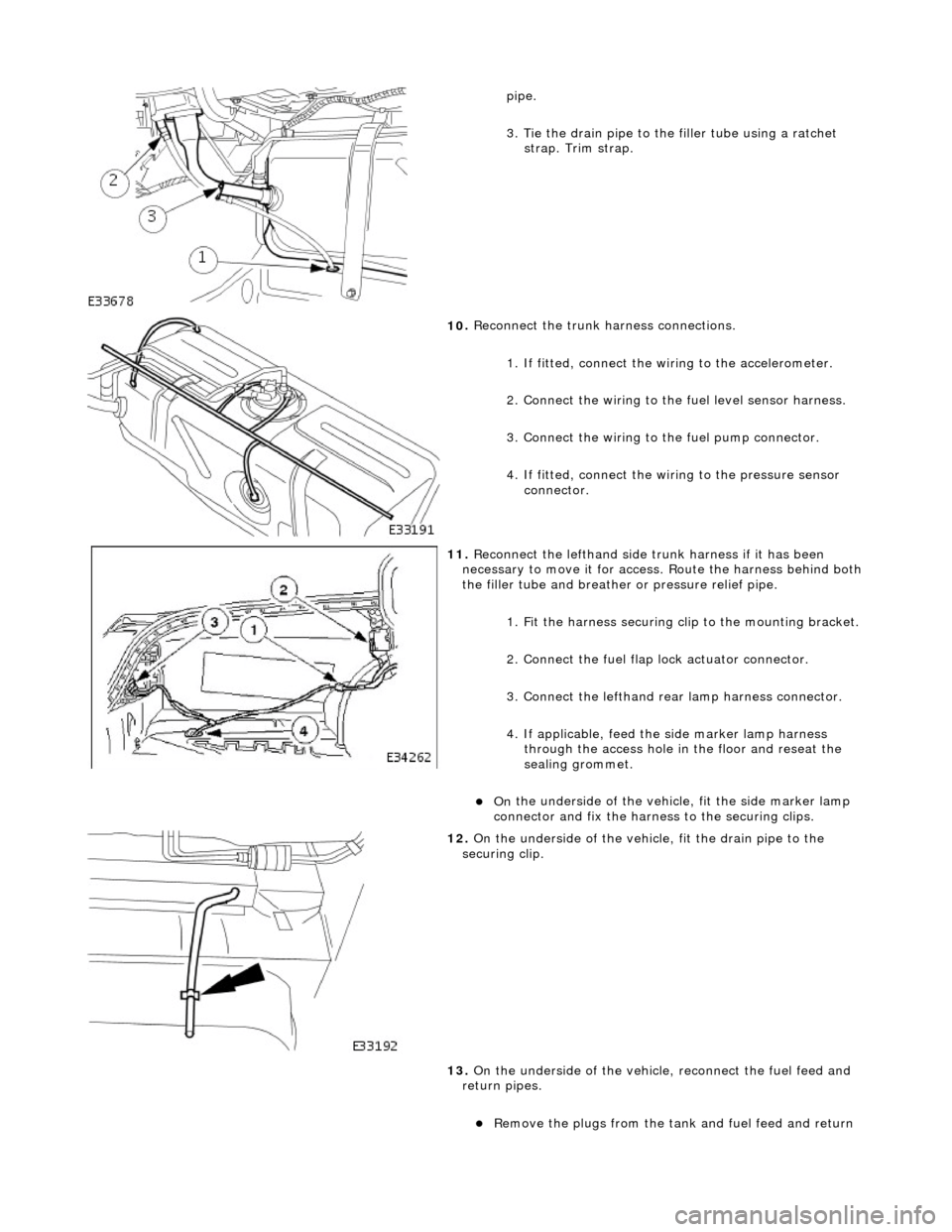
pipe.
3
. Tie the drain pipe to th
e filler tube using a ratchet
strap. Trim strap.
10
.
Reconnect the trunk harness connections.
1. If fitted, connect the wi ring to the accelerometer.
2. Connect the wiring to the fuel level sensor harness.
3. Connect the wiring to th e fuel pump connector.
4. If fitted, connect the wiring to the pressure sensor connector.
11
.
Reconnect the lefthand side trunk harness if it has been
necessary to move it for access. Route the harness behind both
the filler tube and breather or pressure relief pipe.
1. Fit the harness securing cl ip to the mounting bracket.
2. Connect the fuel flap lock actuator connector.
3. Connect the lefthand rear lamp harness connector.
4. If applicable, feed the side marker lamp harness through the access hole in the floor and reseat the
sealing grommet.
On
the underside of the vehicl
e, fit the side marker lamp
connector and fix the harness to the securing clips.
12
.
On the underside of the vehicle, fit the drain pipe to the
securing clip.
13. On the underside of the vehicle, reconnect the fuel feed and
return pipes.
R
emove the plugs from the tank
and fuel feed and return
Page 1743 of 2490
Accelerati
on Control - Accelerator Cable Adjustment
Gen
eral Procedures
1.
Load the Approved Jaguar Diagno stic System with power train
data logger.
2. Connect the Approved Jaguar Diag nostic System to the vehicle.
3. W
ith 'Disable Network Integrity Test - YES/ NO' displayed on
the screen select YES.
4. With new menu displayed on the screen, select ' Engine
Management'.
5. Turn the ignition to ON.
R
emove any previously selected data logger parameters.
6. On data logger select PPS11 an d PPS2 (Pedal demand sensors
1 and 2).
7. On Sedan models only, remove the bulkhead covers on both
sides and the engine compartment rear cover.
8. Cut, remove and discard the ra tchet strap which retains the
throttle cable to the abutment bracket.
9. Ensure there is no tension on the throttle cable by releasing
the throttle cable adjustment nut from the abutment bracket.
10. Record the voltages for both sensors, PPS11 and PPS2.
11. Partially insert the throttle cable adjustment nut into the
abutment bracket.
12. Recheck the voltages for both sensors, PPS11 and PPS2.
13. Where the voltages at step 12 are higher than the voltages
taken at step 10, contin ue to step 15 below.
14. Where the voltages at step 12 are the same as the voltages
taken at step 10, contin ue to step 16 below.
15. Rotate the adjustment nut clockwise (as viewed from the
front of the vehicle) until the same voltages are indicated as in
step 10. Continue to turn thro ugh a part revolution until the
sides of the nut are vertical. Tu rn through a further 90 degrees,
then fully insert the nut into the abutment bracket.
16. Rotate the adjustment nut anti-clockwise (as viewed from the
front of the vehicle) until the indicated voltage starts to
increase. Then rotate the nut clockwise through a part
revolution until the sides are ve rtical. Turn through a further 90
degrees, then fully insert the nut into the abutment bracket.
17. Fit a new ratchet strap to secure the throttle cable adjusting
nut to the abutment bracket.
18. Operate the throttle pedal through 20 full cycles to settle the
cable. Check the voltages now shown, remain the same as in
steps 15 and 16.
19. Check and where necessary adjust the kickdown switch. For
additional information, refer to Section 307
-05A Automatic Transmissi
on/Transaxle External Controls
Sectio
n
307
-05
B
Au
tomatic Transmission/Tra
nsaxle External Controls
.
20
.
On Sedan models only, refit the engine compartment rear
cover and the bulkhead co vers on both sides.
21. Switch the ignition OFF and disconnect the Approved Jaguar
Diagnostic System.