1998 JAGUAR X308 remote control
[x] Cancel search: remote controlPage 22 of 2490

Ambient Air Temperature Sensor (82.20. 02)
Cold Ai
r
Bypass Blend Door Actuator (82.20.86)
Defrost Vent/Register Blend Door Actuator (82.20.84)
Footwell Vent/Duct Blend Door Actuator (80.20.20 or 82.20.85)
Instrument Panel Blend Door Actuator (82.20.83)
Remote Climate Control Module LHD (82.20.65)
Remote Climate Control Module RHD (82.20.65)
413: Instrumentation and Warning Sy
stems
413‐00: Instrument Cluster and Panel Illumination
Description and Operation
Instrument Cluster and Panel Illumination
Removal and Installation
Instrument Panel Dimmer Switch (86.65.07)
413‐01: Instrument Cluster
Description and Operation
Instrument Cluster
Diagnosis and Testing
Instrument Cluster
Removal and Installation
Instrument Clust
er (88.20.01)
413‐06: Horn
Description and Operation
Horn
Diagnosis and Testing
Horn
413‐07: Clock
Description and Operation
Clock
Diagnosis and Testing
Clock
Removal and Installation
Clock (88.15.07)
Page 43 of 2490

Safety Standard
Canister PurgeCANPControls pu
rging of the EVAP canister
Carbon dioxideCO2Colorless gas with
a density of a
pproximately 1.5 ti mes that of air
Carbon mon
oxide
COPoi
sonous gas produced as the re
sult of incomplete combustion
Case G
round
CSE GNDControl modu
le casing ground
Catal
ytic converter
In
-line exhaust system device used to reduce the level of engine exhaust
emissions
Ce
lsius
CSI ter
m for the Centigrade scale, with
freezing point at zero and boiling point
at 100°
Central
Processor Unit
CPUTh
e section of a computer that contai
ns the arithmetic, logic and control
circuits. It performs arithm etic operations, controls instruction processing, and
provides timing signals and other housekeeping operations
Cl
osed Loop
CL
Cl
osed Loop System
CLSControl
system with one
or more feedback loops
Col
umn/Mirror Control
Module
C/MC
M
Control ModuleCMA
self-contained group of electrical/electronic components, designed as a
single replaceable un it, and controlling one or more processes
Controll
er Area Network
CANA
communication system which allows control modules to be linked together
in a network.
Crankshaft Posi
tion
Sensor
CKPSGenerates crankshaft positi on informa
tion in conjunct
ion with the CKPTR (also
generates speed information in certain applications)
Crankshaft Posi
tion
Timing Ring
CKPT
R
Toothe
d ring which
triggers the CKPS
Crankcase Ventila
tion
System
CVSys
tem which scavenges camshaft cover and crankcase emissions and feeds
them into the inlet manifold
Cubic ce nt
imeter
cm
3
Curb weightWe
ight of vehicle with fuel, lubrican
ts and coolant, but excluding driver,
passengers or payload
D
Dat
a Link Connector
DLCConne
ctor providing access and/or control of the vehicle information,
operating conditions, and diagnostic information
De
gree
deg, °Angle or tempe
rature
D
epartment of
Transportation (US)
DO
T
D
epartment of Transport
(UK)
DTp
De
utsche In
stitut für
Normung
DINGerman stand
ards regulation body
Di
agnostic Module
DMSuppl
emental Restraint System (non-c
ontrolling) module for diagnostics
overview
Di
agnostic Test Mode
DTMA le
vel of capability in an OBD system.
May include different functional states
to observe signals, a base level to re ad DTCs, a monitor level which includes
information on signal levels, bi-directional control with on /off board aids, and
the ability to interface with remote diagnosis
Diagnostic Trouble CodeDTCAn al
pha/numeric identifier for a fault
condition identified by the On-Board
Diagnostic (OBD) system
D
ial test indicator
DTIA mechan
ical measuring
instrument, with a rotary indicating pointer
connected to a linear operating probe
D
ifferential pressure
Pressure di
fference betwee
n two regions e.g. between intake manifold and
atmospheric pressures
D
ifferential Pressure
Feedback EGR
DP
FE
An
EGR system that monito
rs differential EGR pressure across a remote orifice
to control EGR flow
D
irect current
dcCurrent which f
lows in on
e direction only, though it may have appreciable
pulsations in its magnitude
Du
al linear switch
DLSJ
-gate switch connected to the TCM on SC vehicles
E
EGR
Temperature EGRT
Sensor
EGRTSens
ing EGR function based on temperature change
EGR Vacu
um Regulator
EVRControls EGR
flow by changi
ng vacuum to the EGR valve
EGR Valve
Position
EVPAn EGR
system that direct
ly monitors EGR valve position to control EGR flow
Electrically E
rasable
Programmable Read-Only
Memory
EEP
ROM
Page 1693 of 2490
Filler Cap and P
ipe
The fuel
filler cap with bayonet-type fixi
ng is located beneath a remote-release sp ring-latched lid on the rear saddle panel
on the left-hand-side of the vehicle.
Fuel Pum
p
The fu
el pump(s) is energized by an ECM co
ntrolled relay. Fuel is drawn by this pu mp and supplied to the fuel injectors via
the fuel line, filter and fuel rails.
Servicing of the fuel pump re quires fuel tank removal.
Ev
aporative Loss Flange Assembly
The evaporative-loss flan
ge asse
mbly is mounted centrally on top of the tank. The flange assembly consists of a removeable
steel cap which mounts the evaporative emissions system vapor outlet valves and, if applicable, a pressure sensor. The
external electrical supply to th e fuel pump(s) is also made via a connector on the flange.
The flange assembly is fixed to the tank by a locking ring which is turned usin g special tool JD-174. A seal is fitted between
the flange assembly and the tank. Three di fferent flange assemblies are applicable according to the evaporative emission
system fitted to the vehicle. The fl ange size and fixing are identical fo r the three systems, as described.
Removal of the evaporative flange assembly is necessary to gain access to th e fuel pump(s) and other internal components.
To remove the evaporative fl ange assembly the fuel tank must first be removed.
The evaporative flange variant assemblies are described, together with service information, in Section 303-13.
Fuel R
eturn
Excess fuel
is directed back to
the fuel tank via a return line.
Fuel Pum
p Relay
The
fuel pump relay,
under control of the ECM, switches power to the fuel pump motor.
I
nertia Fuel Shutoff (IFS) Switch
The IF
S switch is located in the right-hand
side footwell behind the footboard carpet . When activated the switch isolates the
ignition system and fuel pump, releases any locked doors and disables unnecessary electrical systems. The system can be
reset by pressing down the flexible cover on the top of the switch.
• NOTE: The doors will not unlock if the IFS switch is tripped when the ignition switch is in position '0'.
Page 1831 of 2490
other sensors. This feature prevents the effects of sudden changes in air outlet temperatures due to factors such as:
Recirculating air from the engine cooling pack at low vehicle speeds Sudden changes in ambient temperature The effects of water splash
Motorised In-car Aspirator.
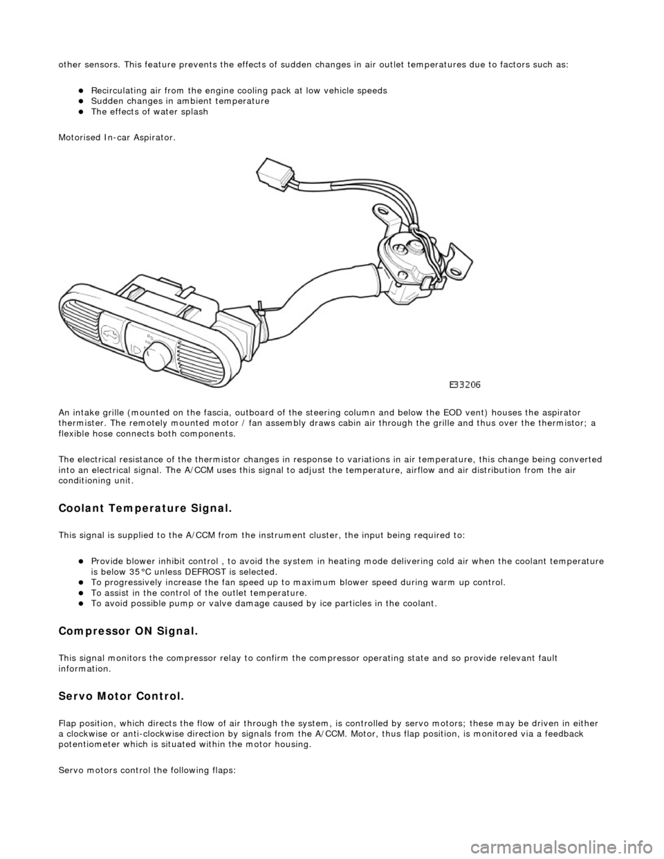
An intake grille (mounted on the fascia , outboard of the steering column and below the EOD vent) houses the aspirator
thermister. The remotely mounted motor / fan assembly draws ca bin air through the grille and thus over the thermistor; a
flexible hose connects both components.
The electrical resistance of the thermistor changes in response to variations in air temperatur e, this change being converted
into an electrical signal. The A/CCM uses this signal to adjust the temperature, airflow and air distribution from the air
conditioning unit.
Coolant Temperature Signal.
This signal is supplied to the A/CCM from the instrument cluster, the input being required to:
Provide blower inhibit control , to avoid the system in heat ing mode delivering cold air when the coolant temperature is below 35°C unless DEFROST is selected. To progressively increase the fan speed up to maximum blower speed during warm up control. To assist in the control of the outlet temperature. To avoid possible pump or valve damage ca used by ice particles in the coolant.
Compressor ON Signal.
This signal monitors the compressor relay to confirm the compressor operating state and so provide relevant fault
information.
Servo Motor Control.
Flap position, which directs the flow of air through the system, is controlled by servo motors; these may be driven in either
a clockwise or anti-clockwise direction by signals from the A/ CCM. Motor, thus flap position, is monitored via a feedback
potentiometer which is situated within the motor housing.
Servo motors control the following flaps:
Page 1846 of 2490
Control Components - Remote Climate Control ModuleLHD RWD
Removal and Installation
Removal
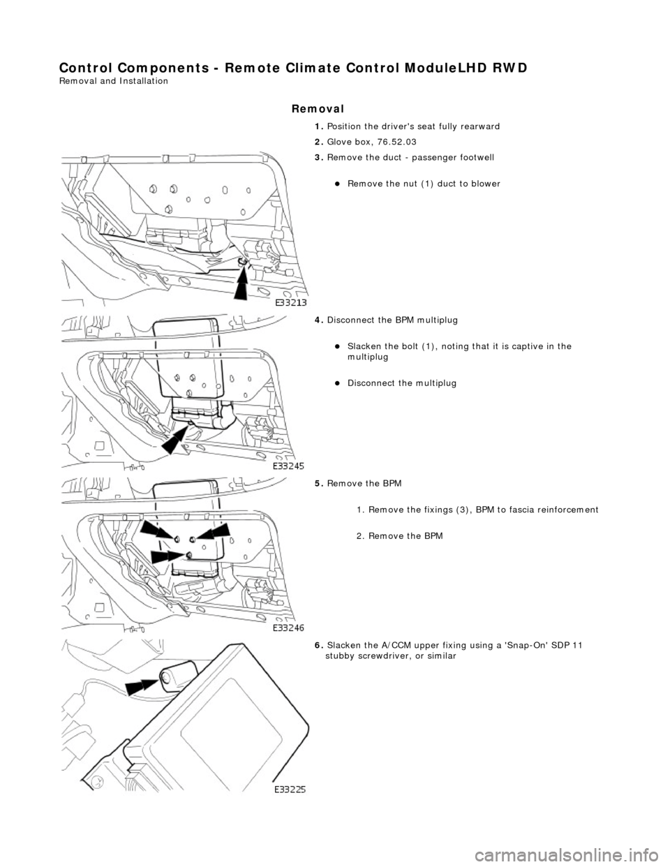
1. Position the driver's seat fully rearward
2. Glove box, 76.52.03
3. Remove the duct - passenger footwell
Remove the nut (1) duct to blower
4. Disconnect the BPM multiplug
Slacken the bolt (1), noting that it is captive in the
multiplug
Disconnect the multiplug
5. Remove the BPM
1. Remove the fixings (3), BPM to fascia reinforcement
2. Remove the BPM
6. Slacken the A/CCM upper fixing using a 'Snap-On' SDP 11
stubby screwdriver, or similar
Page 1848 of 2490
Control Components - Remote Climate Control ModuleRHD RWD
Removal and Installation
Removal
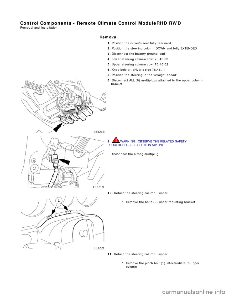
1. Position the driver's seat fully rearward
2. Position the steering column DOWN and fully EXTENDED
3. Disconnect the battery ground lead
4. Lower steering column cowl 76.46.03
5. Upper steering column cowl 76.46.02
6. Knee bolster, driver's side 76.46.11
7. Position the steering in the 'straight ahead'
8. Disconnect ALL (6) multiplugs attached to the upper column
bracket
9. WARNING: OBSERVE THE RELATED SAFETY
PROCEDURES, SEE SECTION 501-20
Disconnect the airbag multiplug
10. Detach the steering column - upper
1. Remove the bolts (2 ) upper mounting bracket
11. Detach the steering column - upper
1. Remove the pinch bolt (1) intermediate to upper column
Page 1856 of 2490
Instrument Cluster - Ins
trument Cluster
D
iagn
osis and Testing
Tests U
s
ing the Portable Diagnostic Unit
Re
fe
r to PDU User Guide
The c
o
mplexity of the electronics involved with the Instrument Cluster and the two multiplexed communication networks
which are connected to it, preclude the use of workshop genera l electrical test equipment. Therefore, reference should be
made to the PDU User Guide for detailed instructions on testing the Instrument Clus ter and associated circuits.
The PDU systematically test s and analyses all functions of the Instrument Clus ter, the various systems controlled by it and
individual sensors which are attached to each separate system.
Where a fault involving a remote sensor e. g. water temperature sensor, is indicated, before replacing the component, some
basic diagnostic methods may be necessary to confirm that connections are good and that wiring is not damaged.
Diagnostics using the PDU is via the CAN network, accessed at the diagnostic connector on the car.
Replaceable Parts
The only replaceable part s
are, General Illumination Bulbs, Direction Indicator Warning Bu
lbs and Main Beam Warning Bulb,
which are all of the conventional filament type. Other warning lamps are LEDs and are not replaceable.
Page 1904 of 2490
Audio Unit - Audio System
Description and Operation
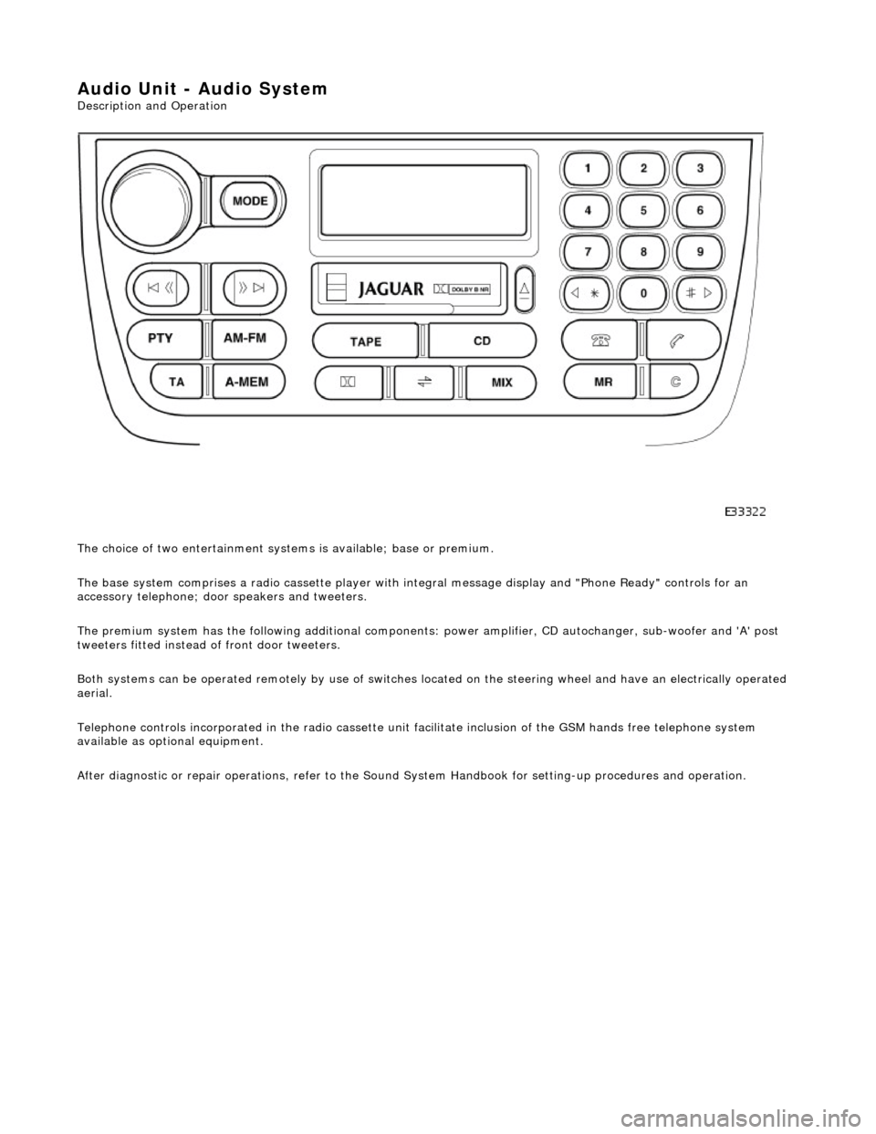
The choice of two entertainment system s is available; base or premium.
The base system comprises a radio cassette player with in tegral message display and "Phone Ready" controls for an
accessory telephone; door speakers and tweeters.
The premium system has the following additional components: power amplifier, CD autochanger, sub-woofer and 'A' post
tweeters fitted instead of front door tweeters.
Both systems can be operated remotely by use of switches loca ted on the steering wheel and have an electrically operated
aerial.
Telephone controls incorporated in the ra dio cassette unit facilitate inclusion of the GSM hands free telephone system
available as optional equipment.
After diagnostic or repair operations, refer to the Sound System Handbook for setting-up procedures and operation.