1998 JAGUAR X308 p0137
[x] Cancel search: p0137Page 1196 of 2490

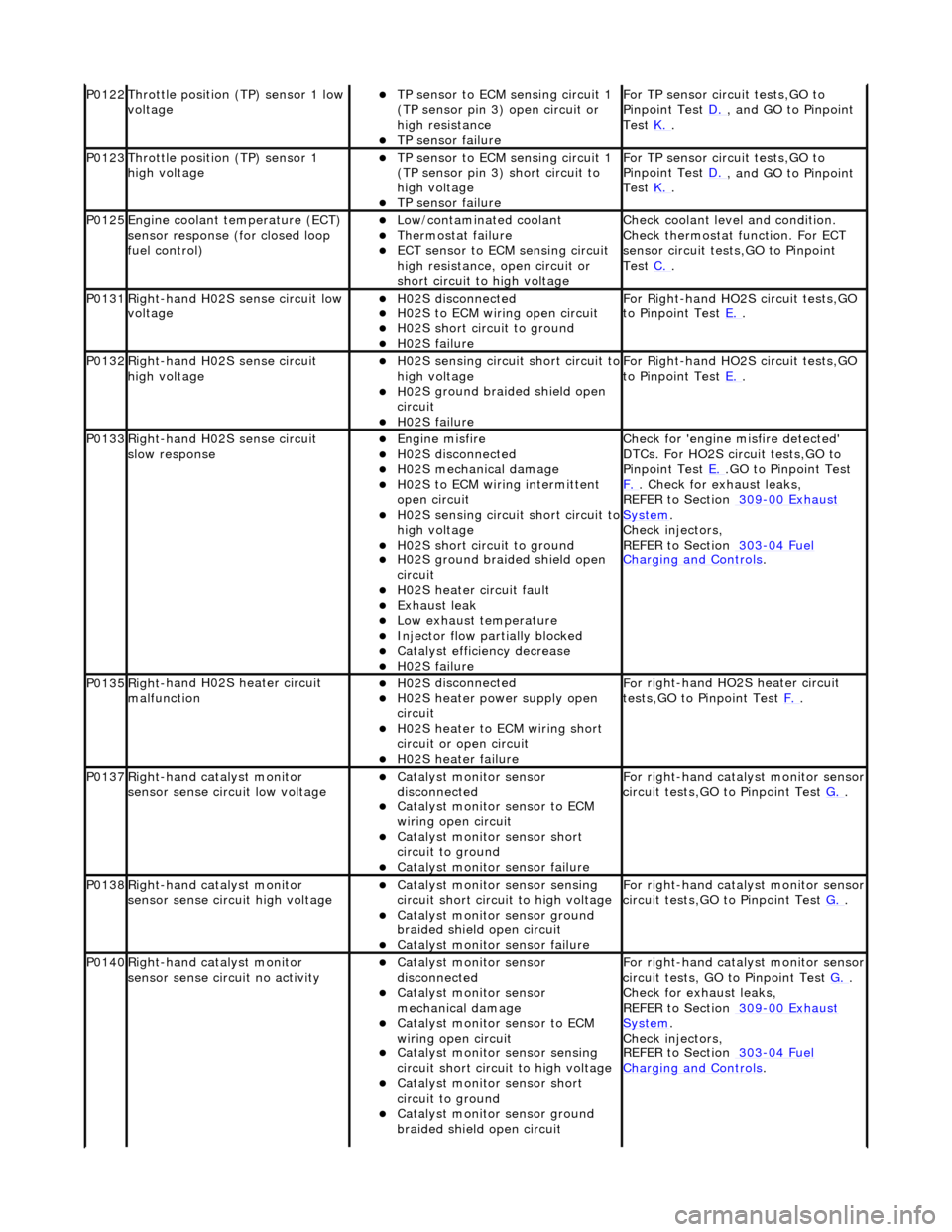
P0122Throttle
position (TP) sensor 1 low
voltage
TP se ns
or to ECM sensing circuit 1
(TP sensor pin 3) open circuit or
high resistance
TP sensor fail
ure
F
o
r TP sensor circ
uit tests,GO to
Pinpoint Test D.
, and GO
to Pinpoint
Test K.
.
P0123Throttl e
position (TP) sensor 1
high voltage
TP se ns
or to ECM sensing circuit 1
(TP sensor pin 3) short circuit to
high voltage
TP sensor fail
ure
F
o
r TP sensor circ
uit tests,GO to
Pinpoint Test D.
, and GO
to Pinpoint
Test K.
.
P0125En
gine coolant temperature (ECT)
sensor response (for closed loop
fuel control)
Low/contaminated coolant Therm o
stat failure
ECT se
ns
or to ECM sensing circuit
high resistance, open circuit or
short circuit to high voltage
Che c
k coolant level and condition.
Check thermostat function. For ECT
sensor circuit tests,GO to Pinpoint
Test C.
.
P0131Right -
hand H02S sense circuit low
voltage
H02 S
disconnected
H0
2S to
ECM wiring open circuit
H0
2S short ci
rcuit to ground
H0
2S fail
ure
F
or R
ight-hand HO2S circuit tests,GO
to Pinpoint Test E.
.
P0132Right-
hand H02S sense circuit
high voltage
H02 S
sensing circuit short circuit to
high voltage
H0 2S groun
d braided shield open
circuit
H0 2S fail
ure
F
or R
ight-hand HO2S circuit tests,GO
to Pinpoint Test E.
.
P0133Right-
hand H02S sense circuit
slow response
Engine m
isfire
H02
S
disconnected
H0
2S mechanical damage
H0
2S to
ECM wiring intermittent
open circuit
H02 S
sensing circuit short circuit to
high voltage
H02S short ci
rcuit to ground
H02S groun
d braided shield open
circuit
H0 2S heater circuit faul
t
Exhaus
t leak
Low e
x
haust temperature
Injector fl
ow parti
ally blocked
Catal
y
st efficiency decrease
H0
2S fail
ure
Chec
k for 'en
gine misfire detected'
DTCs. For HO2S circuit tests,GO to
Pinpoint Test E.
.G
O to Pinpoint Test
F.
. Check for exhaust leaks,
REF
ER to Section 309
-00
Ex
haust
Sy
ste
m
.
Chec k inje
ctors,
REFER to Section 303
-04 Fu
el
Charging and Cont
rols
.
P0135Right
-
hand H02S heater circuit
malfunction
H02 S
disconnected
H0
2S h
eater power supply open
circuit
H0 2S heater to ECM wi
ring short
circuit or open circuit
H0 2S heater fai
lure
F
o
r right-hand HO2S heater circuit
tests,GO to Pinpoint Test F.
.
P0137Right-
hand catalyst monitor
sensor sense circuit low voltage
Catal y
st monitor sensor
disconnected
Catal y
st monitor sensor to ECM
wiring open circuit
Catal y
st monitor sensor short
circuit to ground
Cat a
lyst monitor sensor failure
F
or ri
ght-hand catalyst monitor sensor
circuit tests,GO to Pinpoint Test G.
.
P0138Right -
hand catalyst monitor
sensor sense circuit high voltage
Catal y
st monitor sensor sensing
circuit short circuit to high voltage
Catalyst
monitor sensor ground
braided shield open circuit
Cata
lyst monitor sensor failure
F
or ri
ght-hand catalyst monitor sensor
circuit tests,GO to Pinpoint Test G.
.
P0140Right -
hand catalyst monitor
sensor sense circuit no activity
Catal y
st monitor sensor
disconnected
Catal y
st monitor sensor
mechanical damage
Catal y
st monitor sensor to ECM
wiring open circuit
Catal y
st monitor sensor sensing
circuit short circuit to high voltage
Cataly
st monitor sensor short
circuit to ground
Catalyst
monitor sensor ground
braided shield open circuit
F or ri
ght-hand catalyst monitor sensor
circuit tests, GO to Pinpoint Test G.
.
Check f o
r exhaust leaks,
REFER to Section 309
-00 Ex
haust
Sy
ste
m
.
Chec k inje
ctors,
REFER to Section 303
-04 Fu
el
Charging and Con
t
rols
.
Page 1212 of 2490

CLEAR th
e DTC. TEST the syst
em for normal operation.
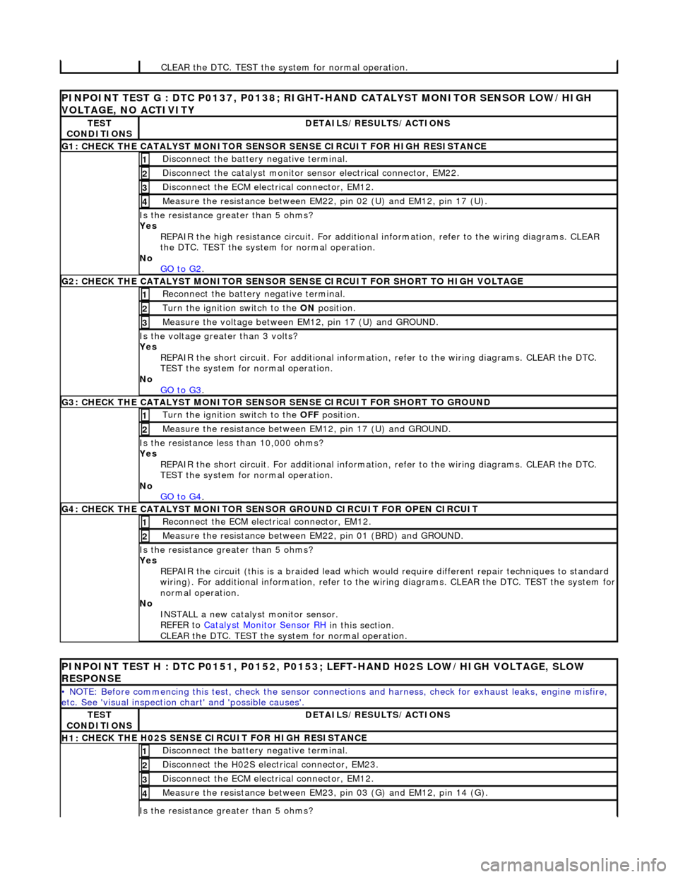
PINPOINT TES
T G : DTC P0137, P0138; RIGH
T-HAND CATALYST MONITOR SENSOR LOW/HIGH
VOLTAGE, NO ACTIVITY
TE S
T
CONDITIONS
D E
TAILS/RESULTS/ACTIONS
G1
: C
HECK THE CATALYST MONITOR SENSOR SENSE CIRCUIT FOR HIGH RESISTANCE
Di
sc
onnect the battery negative terminal.
1
Di
sc
onnect the catalyst monitor sensor electrical connector, EM22.
2
Disc
onne
ct the ECM electrical connector, EM12.
3
Meas
ure t
he resistance between EM22, pin 02 (U) and EM12, pin 17 (U).
4
Is th
e res
istance greater than 5 ohms?
Yes REPAIR the high resistance circui t. For additional information, refer to the wiring diagrams. CLEAR
the DTC. TEST the system for normal operation.
No GO to G2
.
G2: CHECK
THE CATALYST MONITOR SENSOR SE
NSE CIRCUIT FOR SHORT TO HIGH VOLTAGE
Re
connect the battery negative terminal.
1
Turn the ignition swi
t
ch to the ON
position.
2
Measure t
he voltage between EM12, pin 17 (U) and GROUND.
3
Is th
e volt
age greater than 3 volts?
Yes REPAIR the short circuit. For addi tional information, refer to the wiring diagrams. CLEAR the DTC.
TEST the system for normal operation.
No
GO to G3
.
G3: CHECK
THE CATALYST MONITOR SENSOR
SENSE CIRCUIT FOR SHORT TO GROUND
Turn the ignition swit
ch to the OFF
position.
1
Measure t
he resistance between EM12, pin 17 (U) and GROUND.
2
Is t
he resistance less than 10,000 ohms?
Yes REPAIR the short circuit. For addi tional information, refer to the wiring diagrams. CLEAR the DTC.
TEST the system for normal operation.
No GO to G4
.
G4: CHECK
THE CATALYST MONITOR SENSOR
GROUND CIRCUIT FOR OPEN CIRCUIT
Reconn
ect the ECM electrical connector, EM12.
1
Meas
ure t
he resistance between EM22, pin 01 (BRD) and GROUND.
2
Is th
e res
istance greater than 5 ohms?
Yes REPAIR the circuit (this is a braide d lead which would require different repair techniques to standard
wiring). For additional information, refer to the wiring diagrams. CL EAR the DTC. TEST the system for
normal operation.
No INSTALL a new catalyst monitor sensor.
REFER to Catalyst Monitor Sensor RH
in this
section.
CLEAR the DTC. TEST the syst em for normal operation.
PINPOINT TES
T H : DTC P0151, P0152, P0153;
LEFT-HAND H02S LOW/HIGH VOLTAGE, SLOW
RESPONSE
•
NOTE: Before commencing this test, check the sensor connect
ions and harness, check for exhaust leaks, engine misfire,
etc. See 'visual inspection ch art' and 'possible causes'.
TES
T
CONDITIONS
D E
TAILS/RESULTS/ACTIONS
H1:
C
HECK THE H02S SENSE CIRCUIT FOR HIGH RESISTANCE
Di
sc
onnect the battery negative terminal.
1
D
is
connect the H02S electrical connector, EM23.
2
Disc
onne
ct the ECM electrical connector, EM12.
3
Meas
ure t
he resistance between EM23, pin 03 (G) and EM12, pin 14 (G).
4
Is th
e res
istance greater than 5 ohms?
Page 1533 of 2490

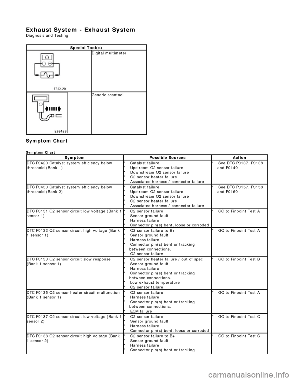
Exhaust System - Exhaust System
Diagnosis and Testing
Symptom Chart
Symptom Chart
Special Tool(s)
Digital multimeter
Generic scantool
SymptomPossible SourcesAction
DTC P0420 Catalyst system efficiency below
threshold (Bank 1)Catalyst failure
Upstream O2 sensor failure
Downstream O2 sensor failure
O2 sensor heater failure
Associated harness / connector failure
*
*
*
*
*See DTC P0137, P0138
and P0140
*
DTC P0430 Catalyst system efficiency below
threshold (Bank 2)Catalyst failure
Upstream O2 sensor failure
Downstream O2 sensor failure
O2 sensor heater failure
Associated harness / connector failure
*
*
*
*
*See DTC P0157, P0158
and P0160
*
DTC P0131 O2 sensor circuit low voltage (Bank 1
sensor 1)O2 sensor failure
Sensor ground fault
Harness failure
Connector pin(s) bent, loose or corroded
*
*
*
*GO to Pinpoint Test A
*
DTC P0132 O2 sensor circuit high voltage (Bank
1 sensor 1)O2 sensor failure to B+
Sensor ground fault
Harness failure
Connector pin(s) bent or tracking
between connections. O2 sensor failure
*
*
*
*
*GO to Pinpoint Test A
*
DTC P0133 O2 sensor circuit slow response
(Bank 1 sensor 1)O2 sensor heater failure / out of spec
Sensor ground fault
Harness failure
Connector pin(s) bent or tracking
between connections. Low exhaust temperature
O2 sensor failure
*
*
*
*
*
*GO to Pinpoint Test B
*
DTC P0135 O2 sensor heater circuit malfunction
(Bank 1 sensor 1)O2 sensor failure
Harness failure
Connector pin(s) bent or tracking
between connections. ECM failure
*
*
*
*GO to Pinpoint Test A
*
DTC P0137 O2 sensor circuit low voltage (Bank 1
sensor 2)O2 sensor failure
Sensor ground fault
Harness failure
Connector pin(s) bent, loose or corroded
*
*
*
*GO to Pinpoint Test C
*
DTC P0138 O2 sensor circuit high voltage (Bank
1 sensor 2)O2 sensor failure to B+
Sensor ground fault
Harness failure
Connector pin(s) bent or tracking
*
*
*
*GO to Pinpoint Test C
*
Page 1557 of 2490

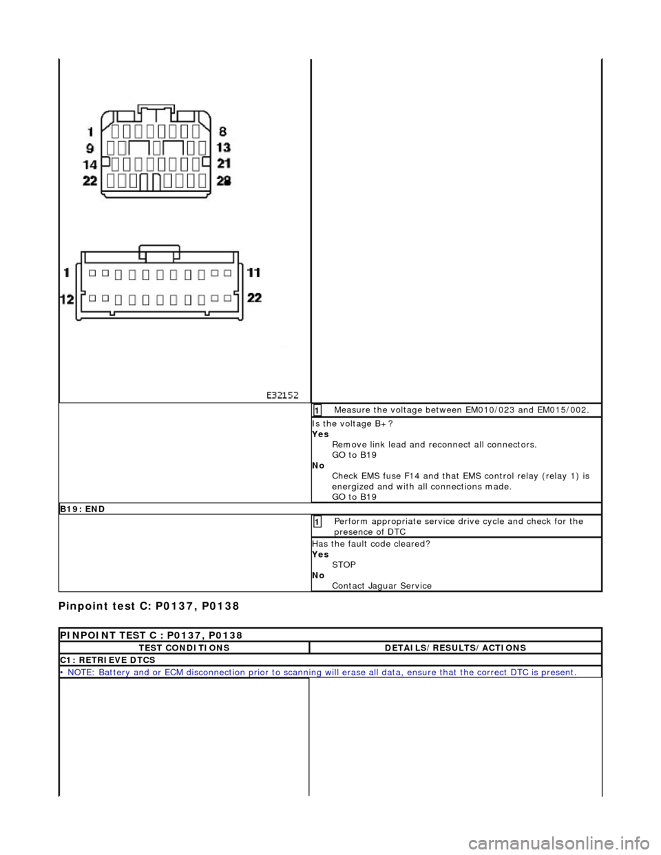
Pinpoint test C: P0137, P0138
Measure the voltage between EM010/023 and EM015/002. 1
Is the voltage B+?
Yes Remove link lead and reconnect all connectors.
GO to B19
No Check EMS fuse F14 and that EMS control relay (relay 1) is
energized and with all connections made.
GO to B19
B19: END
Perform appropriate service drive cycle and check for the
presence of DTC 1
Has the fault code cleared?
Yes STOP
No Contact Jaguar Service
PINPOINT TEST C : P0137, P0138
TEST CONDITIONSDETAILS/RESULTS/ACTIONS
C1: RETRIEVE DTCS
• NOTE: Battery and or ECM disconnection prior to scanning wi ll erase all data, ensure that the correct DTC is present.