Page 2059 of 2490
Interior Trim and Ornamentation - C-Pillar Trim Panel
Removal and Installation
Removal
1. Remove the passenger assist handle.
For additional information, refer to: Passenger Assist Handle
(501-05 Interior Trim and Ornamentation, Removal and
Installation).
2. Detach the rear courtesy/reading light.
3. Remove the rear courtesy/reading light.
Disconnect the electrical connector.
4. Detach the door aperture weatherstrip.
5. Detach the C-pillar trim panel fi r tree fasteners from the BIW.
6. Remove the C-pillar trim pa nel and discard the fir tree
fasteners.
Page 2060 of 2490
Installation
1. To install, reverse the removal procedure.
Fit new fir tree fasteners to the C-pillar trim panel.
Page 2061 of 2490
Interior Trim and Ornamentation - Door Window Control Switch Finish
Panel
Removal and Installation
Removal
Installation
1.
Remove door casing veneer panel. Refer to 76.47.11.
2. Remove door casing. Refer to 76.34.01.
3. Remove door armrest and remo ve switchpack assembly from
armrest. Refer to 76.34.22.
4. Slacken and remove th ree screws securing door glass lift
switch veneer panel to switchpack.
5. Remove veneer panel from switch assembly.
1. Position veneer panel over swit ch assembly and fit and tighten
securing screws.
2. Position switchpack assembly on armrest and fit and tighten
securing screws.
3. Fit armrest to door casing. Refer to 76.34.22.
Page 2062 of 2490
Interior Trim and Ornamentation - Engine Cover
Removal and Installation
Removal
Installation
1.
Remove the passenger side and dr iver side bulkhead covers.
For additional informat ion, refer to Section 501
-02 Front End Body Panels.
2. Remove the engine cover.
1. To install, reverse the removal procedure.
Page 2063 of 2490

Interior Trim and Ornamentation - Floor Covering
Removal and Installation
Removal
1. Remove battery cover and disc onnect ground cable from
battery terminal. Refer to 86.15.19.
2. Remove rear seat cushion. Refer to 76.70.37.
3. Remove front seats. Refer to 76.70.01
4. Remove 'J' gate surroun d. Refer to 76.25.24.
5. Remove centre console finish er veneer panel. Refer to
76.47.26.
6. Remove fascia centre veneer panel. Refer to 76.47.06.
7. Remove centre console assembly. Refer to 76.25.01.
8. Remove 'A' post lower trim pads. Refer to 76.13.30.
9. Remove 'B' post trim pads. Refer to operations in this section.
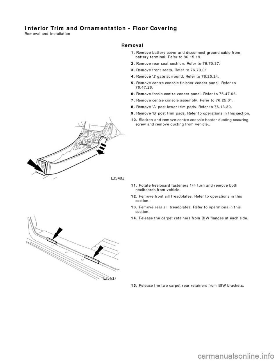
10. Slacken and remove centre console heater ducting securing
screw and remove ducting from vehicle..
11. Rotate heelboard fasteners 1/4 turn and remove both
heelboards from vehicle.
12. Remove front sill treadplates. Refer to operations in this
section.
13. Remove rear sill treadplates. Refer to operations in this
section.
14. Release the carpet retainers fro m BIW flanges at each side.
15. Release the two carpet rear retainers from BIW brackets.
Page 2065 of 2490

2. Ensure that
gear selector is in position 'R'.
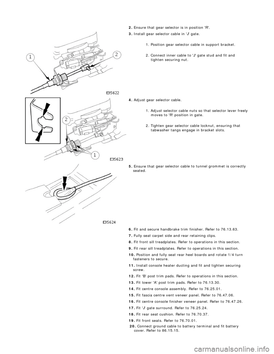
3. Inst
all gear selector cable in 'J' gate.
1. Position gear selector cable in support bracket.
2. Connect inner cable to 'J' gate stud and fit and
tighten securing nut.
4. Adjust
gear selector cable.
1. Adjust selector cable nuts so that selector lever freely
moves to 'R' position in gate.
2. Tighten gear selector ca ble locknut, ensuring that
tabwasher tangs engage in bracket slots.
5. Ensure that
gear selector cable
to tunnel grommet is correctly
seated.
6. Fit and secure handbrake trim finisher. Refer to 76.13.63.
7. Fully seat carpet side and rear retaining clips.
8. Fit front sill treadplates. Refer to operations in this section.
9. Fit rear sill treadplates. Refer to operations in this section.
10. Position and fully seat rear heel boards and rotate 1/4 turn
fasteners to secure.
11. Install console heater ducting and fit and tighten securing
screw.
12. Fit 'B' post trim pads. Refer to operations in this section.
13. Fit lower 'A' post trim pads. Refer to 76.13.30.
14. Fit centre console asse mbly. Refer to 76.25.01.
15. Fit fascia centre ve nt veneer panel. Refer to 76.47.06.
16. Fit centre console finisher vene er panel. Refer to 76.47.26.
17. Fit 'J' gate surround. Refer to 76.25.24.
18. Fit rear seat cushion. Refer to 76.70.37.
19. Fit front seats. Refer to 76.70.01.
20
.
Connect ground cable to batt ery terminal and fit battery
cover. Refer to 86.15.15.
Page 2066 of 2490
Interior Trim and Ornamentation - Folding Tray
Removal and Installation
Removal
Installation
1. Remove screws securing picnic tray hinges to seat back
finisher and remove tray from seat.
2. Remove screws securing hinges to picnic tray. and remove
hinges from tray
3. Remove clips from hinge centre securing screw positions.
4. Remove trim securing screws and remove trim from veneer
panel.
1. Position trim on veneer panel an d install trim securing screws.
Page 2067 of 2490
2.
Install clips at hinge centre securing screw positions.
3. Position hinges on veneer panel and install securing screws.
4. Position hinges on seat back finisher and install securing
screws.