Page 1885 of 2490

If the field were not controlled, the 'B+' output would rise to a level which could damage bulbs and ECMs. The regulator
compares the output voltage to an intern al voltage reference circuit to achieve the controlled output of the generator.
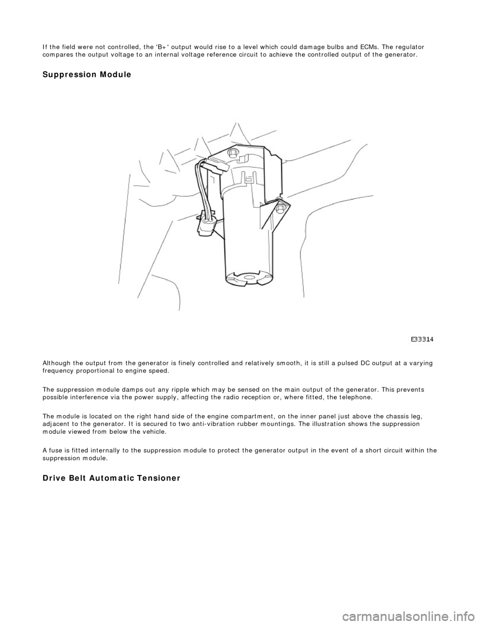
Suppression Module
Although the output from the generator is fi nely controlled and relatively smooth, it is still a pulsed DC output at a varying
frequency proportional to engine speed.
The suppression module damps ou t any ripple which may be sensed on the main output of the generator. This prevents
possible interference via the power supply, affecting the radio reception or, where fitted, the telephone.
The module is located on the right hand side of the engine compartment, on the inner panel just above the chassis leg,
adjacent to the generator. It is secured to two anti-vibration rubber moun tings. The illustration shows the suppression
module viewed from below the vehicle.
A fuse is fitted internally to the suppression module to protect the generator output in the event of a short circuit within th e
suppression module.
Drive Belt Automatic Tensioner
Page 1925 of 2490
Exterior Lighting - Fog Lamp Switch
Removal and Installation
Removal
Installation
1. Remove battery cover and disc onnect ground cable from
battery terminal. Refer to 86.15.19.
2. Remove instrument pa nel veneer panel. Refer to 76.47.24.
3. Remove combined front and rear fog lamp switch pack.
Use a small screwdriver to re lease upper retaining tag.
Position switch for access to connector.
Disconnect connector and remove switch.
1. Position switch pack at instrument panel.
2. Connect harness connector to switch pack
3. Install switch pack in panel, ensuring that retaining tangs are
fully seated.
4. Install instrument panel veneer panel. Refer to 76.47.24.
5. Connect ground cable to batter y terminal and install battery
cover. Refer to 86.15.15.
Page 1933 of 2490
Exterior Lighting - Headlamp Assembly
Removal and Installation
Removal
1. Remove radiator grill. Refer to 76.55.03.
2. Remove radiator grill surro und. Refer to 76.55.15.
3. Remove headlamp trim panel. Refer to 76.11.23.
4. Disconnect headlamp levelling actuator if fitted.
5. Disconnect headlamp assembly harness connector.
6. Remove headlamp assembly to body lower nuts.
7. Remove headlamp to body upper nuts.
Page 1935 of 2490
5. Align headlamp beams.
6. Install headlamp trim panel. Refer to 76.11.23.
7. Install radiator grill surround. Refer to 76.55.15.
8. Install radiator gril l. Refer to 76.55.03.
Page 1959 of 2490
Exterior Lighting - Side Turn Signal Lamp
Removal and Installation
Removal
Installation
1. Remove side repeater lamp.
Applying downward pressure, compress retaining clips and
release lamp upper edge from fender.
Withdraw lamp from panel and disconnect harness
connector.
1. Position lamp at fender and connect harness connector.
2. Position lower edge of lamp in fender aperture and apply
downward pressure to compress clip.
3. Pivot lamp to seat upper edge in fender.
Page 1963 of 2490

Rear courtesy/ reading lamps
Each rear quarter of the passenger compartment is fitted with combined lighting units comprising; a rear courtesy lamp and
reading lamp. The courtesy lamps operate automatically whenever a rear door is opened; the reading lamps function when
the integral switches are operated by occupants of the vehicle.
Trunk lamps
The trunk trim panel is fitted with lamps which operate auto matically whenever the trunk lid is opened; the switch is
incorporated within the latch mechanism.
Vanity mirror lamps
The vanity mirror lamps, two on each sun visor, operate auto matically when the mirror flap is opened, provided the sun
visor spindle is engage d in the stowage clip.
Operation
The BPM provides an enable signal for the glovebox, vanity mirror, trunk lid and map lamps. Actuation of the relevant
switch provides an earth path to the lamp.
The rear passenger reading lamps receive a supply di rect from fuse F10 in the RH heelboard fuse-box.
The front and rear courtesy lamps have separa te fade functions controlled by the BPM.
The door hazard / puddle lamps are controll ed locally by the relevant Door Module.
Fault analysis must be undertaken using the PDU, refer to Diagnosis and Testing.
Refer to the relevant Electrical Guid e for details of circuit operation.
Page 1982 of 2490
Module Communications Network - Battery Junction Box (BJB)
Removal and Installation
Removal
1. Disconnect battery ground cable; refer to 86.15.19.
2. Remove cover from fuse box.
1. Release securing tangs.
2. Remove cover.
3. Remove positive supply power cable.
1. Displace cover.
2. Remove nut.
3. Disconnect cable.
4. Displace fuse box from mounting panel for access.
1. Release securing latch, upwards.
Release fuse box from mountin g panel by displacement
towards spare wheel.
5. Remove fuse box.
1. Identify and disconne ct harness connectors.
Page 1984 of 2490
Module Communications Network - Central Junction Box (CJB) Removal and Installation
Removal
Installation
1. Disconnect battery ground cable; refer to 86.15.19.
2. Remove heelboard trim panel.
3. Remove positive supply power cable and displace fuse box.
1. Displace cover.
Remove nut which secures posi tive cable to fuse box.
2. Disconnect cable.
3. Remove nuts.
4. Remove fuse box.
Identify and disconnect harness connectors.
5. Remove fuses and relay.
1. Remove relay.
2. Identify each fuse and remove them.
The value and position of each fuse is illustrated on the lid of the
trunk compartment fuse box - for all fuse boxes on the vehicle.
1. Installation is reverse of removal.
2. Reconnect battery ground cable; refer to 86.15.15.