Page 2068 of 2490
Interior Trim and Ornamentation - Folding Tray Finish Panel
Removal and Installation
Removal
Installation
1. Move picnic tray to fully down position.
2. Remove screws securing picnic tray hinges to back finisher
and remove tray from seat.
3. Remove the two back finisher to seat securing screws.
4. Release finisher from side mount ing clips and remove finisher
from seat.
5. Remove three screws se curing picnic tray top rail veneer panel
to seat finisher and remove veneer panel.
Page 2069 of 2490
1.
Position top rail veneer panel on finisher, locate two dowels
and install securing screws.
2. Position back finisher on seat and install lower securing screws.
3. Position and fully seat fini sher side securing clips.
4. Position picnic tray on back fi nisher and install hinge securing
screws.
5. Move picnic tray to up position.
Page 2071 of 2490
Interior Trim and Ornamentation - Front Door Trim Panel Finish Panel
Removal and Installation
Removal
Installation
1. Remove interior door handle escutcheon.
Remove cover from door ha ndle escutcheon securing
screw and slacken and remove screw.
Pull door handle inwards and exercising care to avoid
damaging tweeter, remove escutcheon from casing.
2. Remove veneer panel from casing.
1. Using a thin plastic leve r, carefully ease rear of
veneer panel inwards to release the two rear
securing tangs.
2. Slide veneer panel re arwards to release front
retainers.
1. Position veneer panel on casing and slide forward to engage
front retainers.
2. Using a soft pad or cloth, press re ar of panel firmly to seat the
securing tangs.
3. Fit door handle escutcheon.
Page 2073 of 2490
Interior Trim and Ornamentation - Front Door Trim Panel
Removal and Installation
Removal
1. Remove interior door handle escutcheon.
Remove cover from door ha ndle escutcheon securing
screw and slacken and remove screw.
Pull door handle inwards and exercising care to avoid
damaging tweeter, remove escutcheon from casing.
2. Remove door casing veneer panel. Refer to 76.47.11.
3. Slacken and remove the armres t centre securing screw.
4. Carefully release the eight fasten ers securing lower section of
casing to door.
5. Lift rear edge of door casing to release retaining clip housing
from door panel.
Page 2074 of 2490
6. Lift casing clear of door wais t flange and lock button and
withdraw for access.
7. Using pliers, remove housing from clip and fit to door panel.
8. Disconnect tweeter, speaker, puddle lamp and switchpack
harness multiplugs.
9. Remove armrest lower securing clip housing from casing. and
refit to door.
10. Remove door inner waist se al from holder, slacken and
remove screws securing waist seal holder and remove seal
holder.
11. Remove armrest from door casing. Refer to 76.34.22.
12. Slacken and remove puddle la mp securing screws and
remove lamp assembly from casing.
13. Remove pocket from door casing.
Page 2075 of 2490

Installation
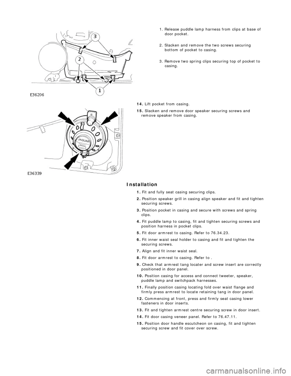
1. Release puddle lamp harness from clips at base of door pocket.
2. Slacken and remove th e two screws securing
bottom of pocket to casing.
3. Remove two spring clips securing top of pocket to casing.
14. Lift pocket from casing.
15. Slacken and remove door sp eaker securing screws and
remove speaker from casing.
1. Fit and fully seat casing securing clips.
2. Position speaker grill in casing align speaker and fit and tighten
securing screws.
3. Position pocket in casing and secure with screws and spring
clips.
4. Fit puddle lamp to casing, fit and tighten securing screws and
position harness in pocket clips.
5. Fit door armrest to casing. Refer to 76.34.23.
6. Fit inner waist seal holder to casing and fit and tighten the
securing screws.
7. Align and fit inner waist seal.
8. Fit door armrest to casing. Refer to .
9. Check that armrest tang locater and screw insert are correctly
positioned in door panel.
10. Position casing for access and connect tweeter, speaker,
puddle lamp and switchpack harnesses.
11. Finally position casing locating fold over waist flange and
firmly press armrest to locate retaining tang in door panel.
12. Commencing at front , press and firmly seat casing lower
fasteners in door inserts.
13. Fit and tighten armrest centre se curing screw in door insert.
14. Fit door casing veneer panel. Refer to 76.47.11.
15. Position door handle escutche on on casing, fit and tighten
securing screw and fit cover over screw.
Page 2076 of 2490

Interior Trim and Ornamentation - Headliner
Removal and Installation
Removal
Vehicles with roof opening panel
All vehicles
1. Remove the roof opening panel trim.
For additional information, refer to: Roof Opening Panel Trim
(501-17 Roof Opening Panel, Removal and Installation).
2. Remove both C-pill ar trim panels.
For additional information, refer to: C
-Pillar Trim Panel (501-05
Interior Trim and Ornamentatio n, Removal and Installation).
3. Remove both A-pill ar trim panels.
For additional information, refer to: A
-Pillar Trim Panel (501-05
Interior Trim and Ornamentatio n, Removal and Installation).
4. Remove the overhead console.
For additional information, refer to: Overhead Console
(501-12
Instrument Panel and Console, Removal and Installation).
5. Remove the rear window glass.
For additional information, refer to: Rear Window Glass
(501-
11 Glass, Frames and Mechanis ms, Removal and Installation).
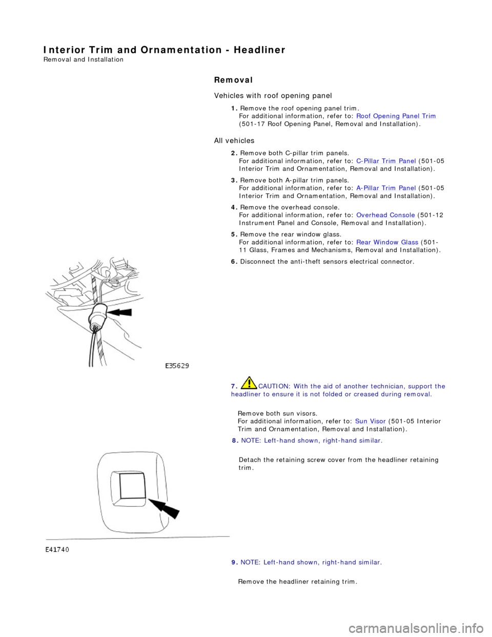
6. Disconnect the anti-theft se nsors electrical connector.
7. CAUTION: With the aid of an other technician, support the
headliner to ensure it is not folded or creased during removal.
Remove both sun visors.
For additional information, refer to: Sun Visor
(501-05 Interior
Trim and Ornamentation, Re moval and Installation).
8. NOTE: Left-hand shown, right-hand similar.
Detach the retaining screw cove r from the headliner retaining
trim.
9. NOTE: Left-hand shown, right-hand similar.
Remove the headline r retaining trim.
Page 2079 of 2490

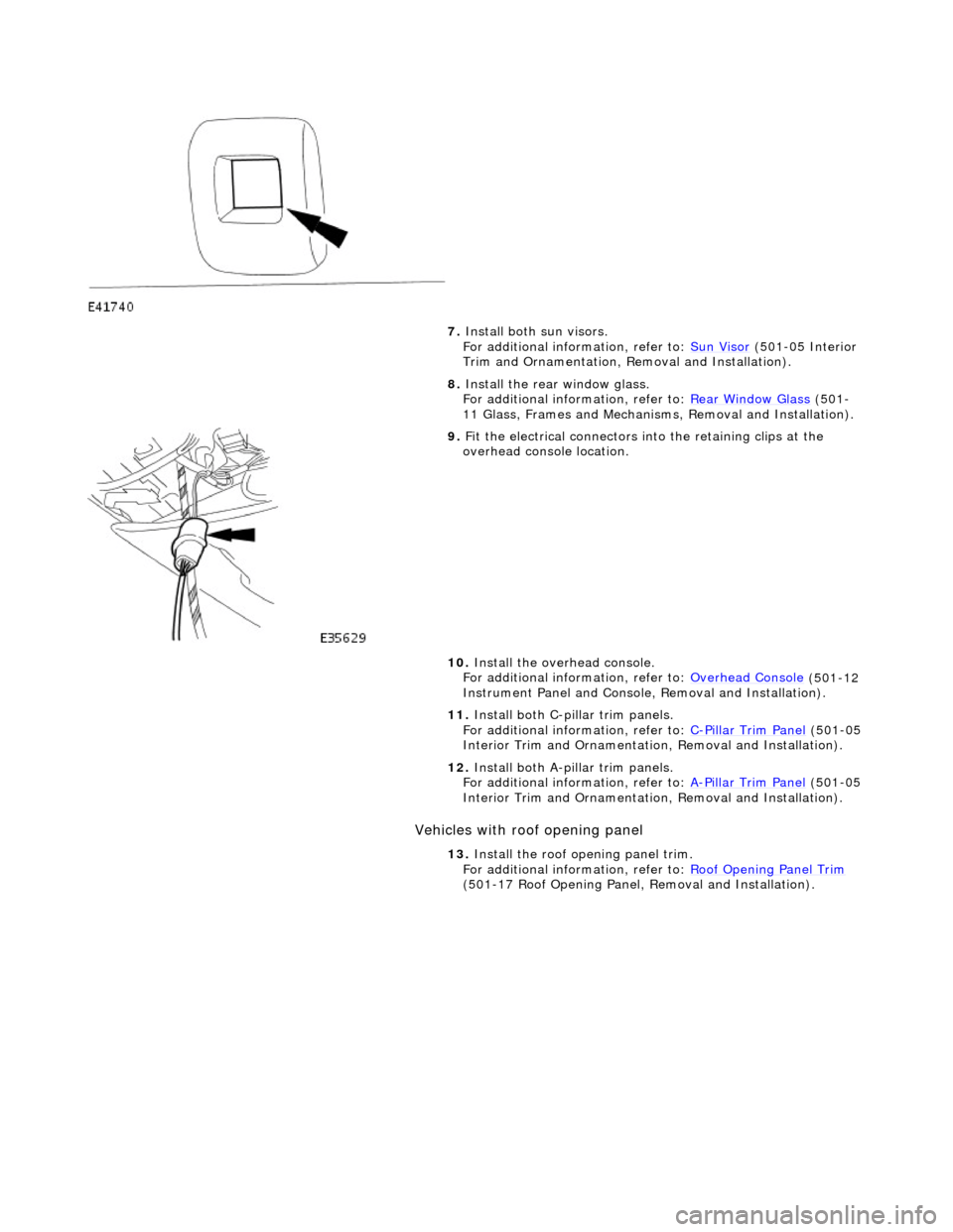
Vehicles with roof opening panel
7. Install both sun visors.
For additional information, refer to: Sun Visor (501-05 Interior
Trim and Ornamentation, Re moval and Installation).
8. Install the rear window glass.
For additional information, refer to: Rear Window Glass
(501-
11 Glass, Frames and Mechanis ms, Removal and Installation).
9. Fit the electrical connectors into the retaining clips at the
overhead console location.
10. Install the overhead console.
For additional information, refer to: Overhead Console
(501-12
Instrument Panel and Console, Removal and Installation).
11. Install both C-pillar trim panels.
For additional information, refer to: C
-Pillar Trim Panel (501-05
Interior Trim and Ornamentatio n, Removal and Installation).
12. Install both A-pillar trim panels.
For additional information, refer to: A
-Pillar Trim Panel (501-05
Interior Trim and Ornamentatio n, Removal and Installation).
13. Install the roof opening panel trim.
For additional information, refer to: Roof Opening Panel Trim
(501-17 Roof Opening Panel, Removal and Installation).