Page 46 of 2490

Meter (measurement)m
Me
tric (screw thread, e.g.
M8)
M
MicrofaradMFDUni t
of electrical capacitance, one millionth of a farad
Mi
ll
imeter
mm
Mi
ll
imeter of mercury
mm
Hg
Mill
isecond
ms
Min
i
mum
mi
n.
Min u
te
minut
e
Model YearMY
ModuleMSelf
contained group of electrical/electronic components which is designed as
a single replaceable unit
Modulating signalMDA sh
ift process signal to the TCM on SC vehicles
Motorized In
-Car
AspiratorMIAD e
vice which constantly samples cabi
n temperature by passing air over a
sensor, and communicates with the A/ CCM to modify A/C system performance
to suit
Mult i Prot
ocol Adaptor
MPAAn i
n
terpreter for the various data
languages present on a vehicle
N
Nati
onal Institute of
Occupational Safety and
Health (US)
NIO S
H
Ne
wto
n
NSI unit of force. 1
N = 0.224
8 pounds force
Ne
wto
n meter
NmSI unit of torque. Must not be
co
nfused with nm (nanometer)
Ni
tr
ous Oxide
NO
xCompounds of nit rogen and oxygen fo rmed at high temperatures. Major
sourc
e of exhaust-gas air pollution
No
n
-Volatile Random
Access Memory
NVR A
M
R
A
M which retains memory even
if power supply is interrupted
Normal
ly aspirated
F
u
eling system using intake air at atmo
spheric pressure; not supercharged or
turbocharged
N ormal
ly Closed
NC
N
o
rmally Open
NO
No
r
th American
Specification
NASVehicles f or sal
e in the USA and Canadian markets
Nu
mbe
r
No
.
O
Oc
cupational Safety and
Health Administration
(US)
OS H
A
O
n
-Board Diagnostic
OB
DA system that moni
tors some or all co
mputer input and output control signals.
Signal(s) outside the pre-de termined limits imply a fault in the system or a
related system
O n
-Board Refueling
Vapor Recovery
OR V
R
O
riginal
Equipment
Manufacturer
OE M
Outp
ut
O/
PAn electrical o u
tput signal from a controlling device
Ou
ts
ide diameter
o.
d
ia
O
xides of
nitrogen
NO
x
Oxygen senso
r
O2
SA s
ensor which detects oxygen content in the exhaust gases
P
Parameter Identifi
erPIDAn in
dex number referring to a parame
ter within a module without knowledge
of its storage location
Park N e
utral Position
PN
P
Park N e
utral Position
Switch
PN PSIndic
ates the selected non-drive modes of the (automatic) transmission
Part numberpart no.
Portable Diag
nostic Un
it
PD
UCompre hen
sive electrical diagnosis system specific to Jaguar vehicles
Posi
ti
on
po
s'n
Power As si
sted Steering
PASHydraul
i
c pump-assisted steering system
Power Steer
i
ng Pressure
PSP
Programmable Elect
r
onic
Control Units System
PECU SProcess whereb y
a common ECM is progra
mmed on the production line to suit
the market requirements of a particular vehicle
Programmable Read-O
nly
PROMRO
M with some provision for setting
the stored data after manufacture
Page 1151 of 2490
The evaporative l
oss flange assembly is fitted to the top of the tank via a seal and locking ring. The assembly is removeable
complete with the fitted components.
The vapour vent / rollover valve is a push fit via a sealing grommet. The fuel pump connector is push fitted and crimped
into a location tube on the underside of the flange.
It
em
Par
t Number
De
scription
1—Vapour vent /
rollover protection valve
2—Fue
l pump connector
3—Evaporative loss flange locking rin
g
Evaporative Flang
e Assembly
Page 1153 of 2490
tank vapou
r pressure.
Canister purge operation is as described in Evaporative Emissions Control.
Evaporative Flange Assembly
The evaporative loss flange assembly is fitted to the top of the tank via a seal and locking ring. The assembly is removeable
complete with the fitted components.
The vapour vent / rollover valve and pressure sensor are a pu sh fit via sealing grommets. The fuel pump connector is push
fitted and crimped into a location tu be on the underside of the flange.
It
em
Par
t Number
De
scription
1—Vapour vent /
rollover protection valve
2—Pres
sure sensor
3—Fue
l pump connector
4—Evaporative loss flange locking rin
g
Page 1158 of 2490

The fuel fil
ler cap is the same as
that used on non-ORVR systems.
The check valve assembly is a push fit into the end of the fuel filler tube and is accessible with the evaporative flange
removed. The valve has a light spring load ing and opens under the inflow of fuel.
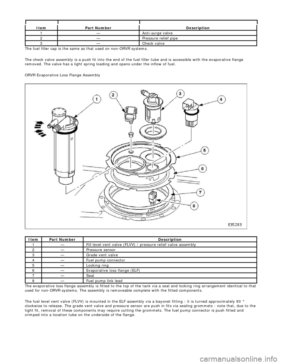
ORVR Evaporative Loss Flange Assembly
The evaporative loss flange assembly is fitted to the top of the tank via a seal and locking ring arrangement identical to that
used for non-ORVR systems. The assembly is re moveable complete with the fitted components.
The fuel level vent valve (FLVV) is mounted in the ELF assembly via a bayonet fitting : it is turned approximately 90 °
clockwise to release. The grade vent valve and pressure sensor are push in fits via sealing gromme ts : note that, due to the
tight fit, removal of these components may require cutting the grommets. The fuel pump connector is push fitted and
crimped into a location tube on the underside of the flange.
It e
m
Par
t
Number
De
scr
iption
1—An
ti-s
urge valve
2—Pressure rel
i
ef pipe
3—Check v
a
lve
It
e
m
Par
t
Number
De
scr
iption
1—Fi
ll
level vent valve (FLVV) /
pressure relief valve assembly
2—Pres
sure
sensor
3—Grade vent
valve
4—Fue
l
pump connector
5—Lockin
g rin
g
6—Evaporative loss flange (ELF)
7—Seal
8—F
u
el pump link lead