Page 1862 of 2490
Clock - Clock
Diagnosis and Testing
Tests Using the Portable Diagnostic Unit
Refer to PDU User Guide
The complexity of the electronics involved with the various Electronic Control Modules and the two multiplexed
communication networks, preclude the use of workshop general electrical test equipment. Therefore, reference should be
made to the PDU User Guide for detailed in structions on testing the clock circuit.
The PDU systematically tests an d analyses the clock and the electrucal connections to it.
Where a fault involving the clock is indicated by the PDU, befo re replacing the clock, some basic diagnostic methods may be
necessary to confirm that connections are good and that wiring is not damaged.
Page 1869 of 2490

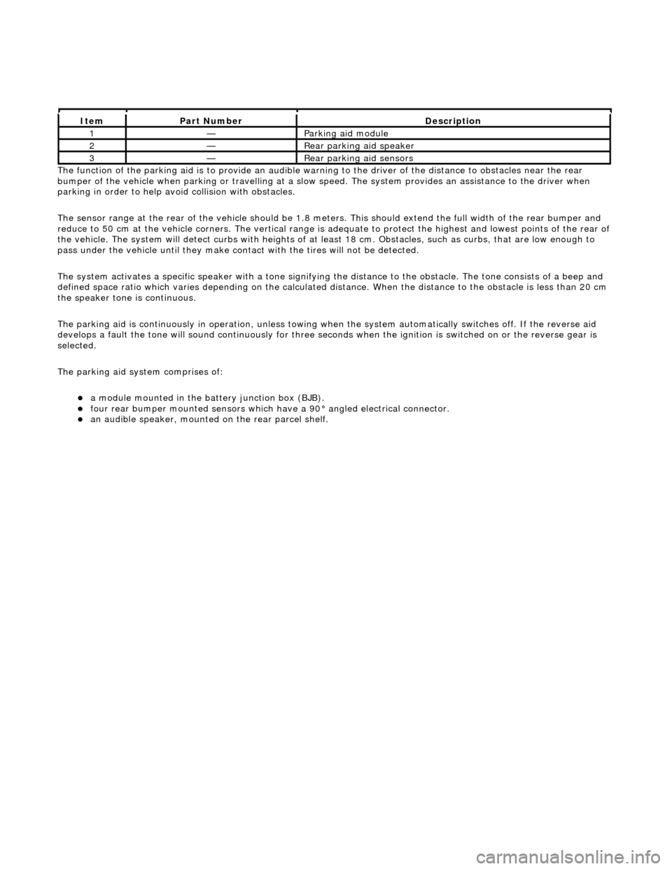
The functi
on of the parking aid is to prov
ide an audible warning to the driver of the distance to obstacles near the rear
bumper of the vehicle when parking or travelling at a slow sp eed. The system provides an assistance to the driver when
parking in order to help avoid collision with obstacles.
The sensor range at the rear of the vehicl e should be 1.8 meters. This should extend the full width of the rear bumper and
reduce to 50 cm at the vehicle co rners. The vertical range is adequate to protec t the highest and lowest points of the rear of
the vehicle. The system will detect curbs with heights of at least 18 cm. Obstacles, such as curbs, that are low enough to
pass under the vehicle until they make contact with the tires will not be detected.
The system activates a specific speaker with a tone signifying the distance to the obstacle. The tone consists of a beep and
defined space ratio which varies depending on the calculated distance. When the distance to the obstacle is less than 20 cm
the speaker tone is continuous.
The parking aid is continuously in operation, unless towing wh en the system automatically switches off. If the reverse aid
develops a fault the tone will sound continuously for three seconds when the igni tion is switched on or the reverse gear is
selected.
The parking aid system comprises of:
a
module mounted in the batte
ry junction box (BJB).
fou
r rear bumper mounted sensors which have a 90° angled electrical connector.
an audible speaker, moun
ted on
the rear parcel shelf.
It
em
Par
t Number
De
scription
1—Parkin
g aid module
2—Rear
parking aid speaker
3—Rear
parking aid sensors
Page 1870 of 2490
Parking Aid - Parking Aid
Diagnosis and Testing
Inspection and Verification
1.1. Verify the customer concern.
2. 2. Visually inspect for obvious signs of mechanical or electrical damage.
Visual Inspection Chart
3. 3. If an obvious cause for an observed or reported concern is found, correct the cause (if possible) before proceeding to the next step
4. 4. If the cause is not visually evident, verify the sympto m and refer to the Jaguar approved diagnostic system.
Electrical
Fuse(s) Relay(s) Wiring Harness Electrical connector(s) Rear parking aid sensor(s) Rear parking aid speaker Reversing lamp switch Parking aid module
Page 1871 of 2490
Parking Aid - Parking Aid Module
Removal and Installation
Removal
1. Remove the luggage compartment floor panel.
2. Remove the battery cover.
3. Reposition the cover from the battery junction box (BJB).
4. Reposition the parking aid module.
5. Remove the parking aid module.
Page 1876 of 2490

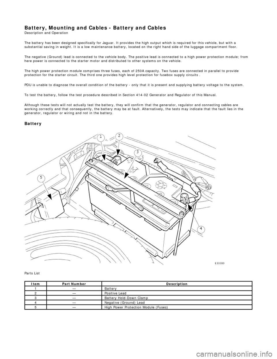
Battery, Mounting and Cables - Battery and Cables Description and Operation
The battery has been designed specifically for Jaguar. It provides the high output which is required for this vehicle, but with a
substantial saving in weight. It is a low maintenance battery, located on the right ha nd side of the luggage compartment floor.
The negative (Ground) lead is connected to the vehicle body. The positive lead is connected to a high power protection module; from
here power is connected to the starter motor an d distributed to other systems on the vehicle.
The high power protection module comprises three fuses, each of 250A capacity. Two fuses are connected in parallel to provide
protection for the starter circuit. Th e third one provides high level protection for fusebox supply circuits .
PDU is unable to diagnose the overall condition of the battery - only that it is present and supplying battery voltage to the system.
To test the battery, follow the test procedure described in Section 414-02 Generator and Regulator of this Manual.
Although these tests will not actually test the battery, they will confirm that the generator, regulator and connecting cables are
working correctly and that conseq uently, the battery may be at fault. Alternatively, the tests may indicate that the fault lies in the
generator, regulator or wiring and not in the battery.
Battery
Parts List
ItemPart NumberDescription
1—Battery
2—Positive Lead
3—Battery Hold-Down Clamp
4—Negative (Ground) Lead
5—High Power Protection Module (Fuses)
Page 1880 of 2490
Battery, Mounting and Cables - Battery Positive Cable
Removal and Installation
Removal
Installation
1.
Remove the luggage compartment floor panel (when standard
size spare wheel is supplied) and the cover from the battery.
2. Disconnect the positive lead.
1. Slacken the clamp of the po sitive lead at the battery
terminal. Disconnect the positive lead from the
battery terminal.
2. Remove the cover from th e high power protection
module for access to the positive supply stud.
3. Remove the positive lead.
1. Remove the nut from the positive supply stud.
2. Remove the positive lead.
1. Installation is the reverse of removal.
2. Perform the Battery Reconnection Procedure described in this
section.
Page 1883 of 2490

Belt tension is achieved by an automatic tensioner; neither the belt nor the tensioner require service apart from checking
the belt wear indicators at each normal service interval.
The minimum service life of the drive belt is 100,000 miles.
Never apply oil to the belt or to the belt tensioner.
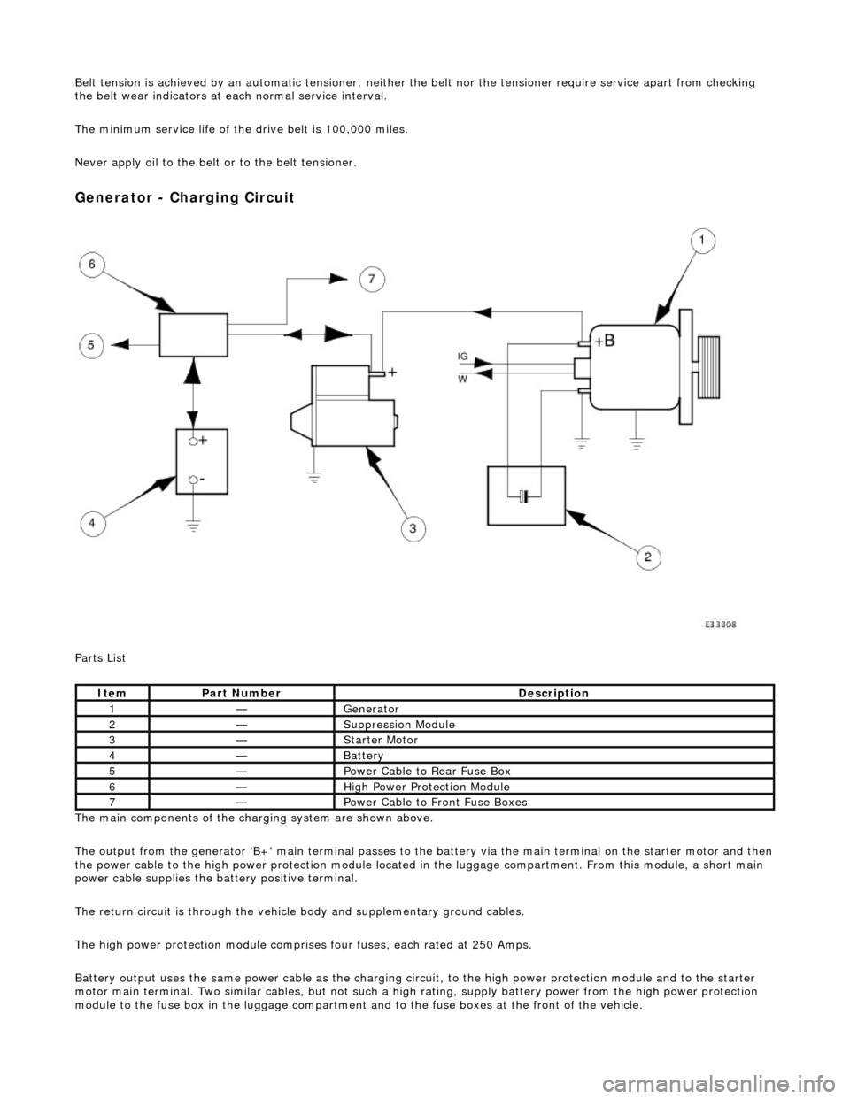
Generator - Charging Circuit
Parts List
The main components of the charging system are shown above.
The output from the generator 'B+' main te rminal passes to the battery via the main terminal on the starter motor and then
the power cable to the high power protection module located in the luggage compartment. From this module, a short main
power cable supplies the ba ttery positive terminal.
The return circuit is through the vehicle body and supplementary ground cables.
The high power protection mo dule comprises four fuses, each rated at 250 Amps.
Battery output uses the same power cable as the charging circ uit, to the high power protection module and to the starter
motor main terminal. Two similar cables, but not such a high rating, supply battery power from the high power protection
module to the fuse box in the luggage compartment an d to the fuse boxes at the front of the vehicle.
ItemPart NumberDescription
1—Generator
2—Suppression Module
3—Starter Motor
4—Battery
5—Power Cable to Rear Fuse Box
6—High Power Protection Module
7—Power Cable to Front Fuse Boxes
Page 1884 of 2490

The interference suppression module (where fitted) connects to the generator main terminal 'B +' and a ground stud on the
rear face of the generator.
A multi-plug (3 pin) is connecte d to the rear of the generator:
Pin 1 not connected. Pin 2 ignition supply to the regulator. Pin 3 output to the charge warning lamp.
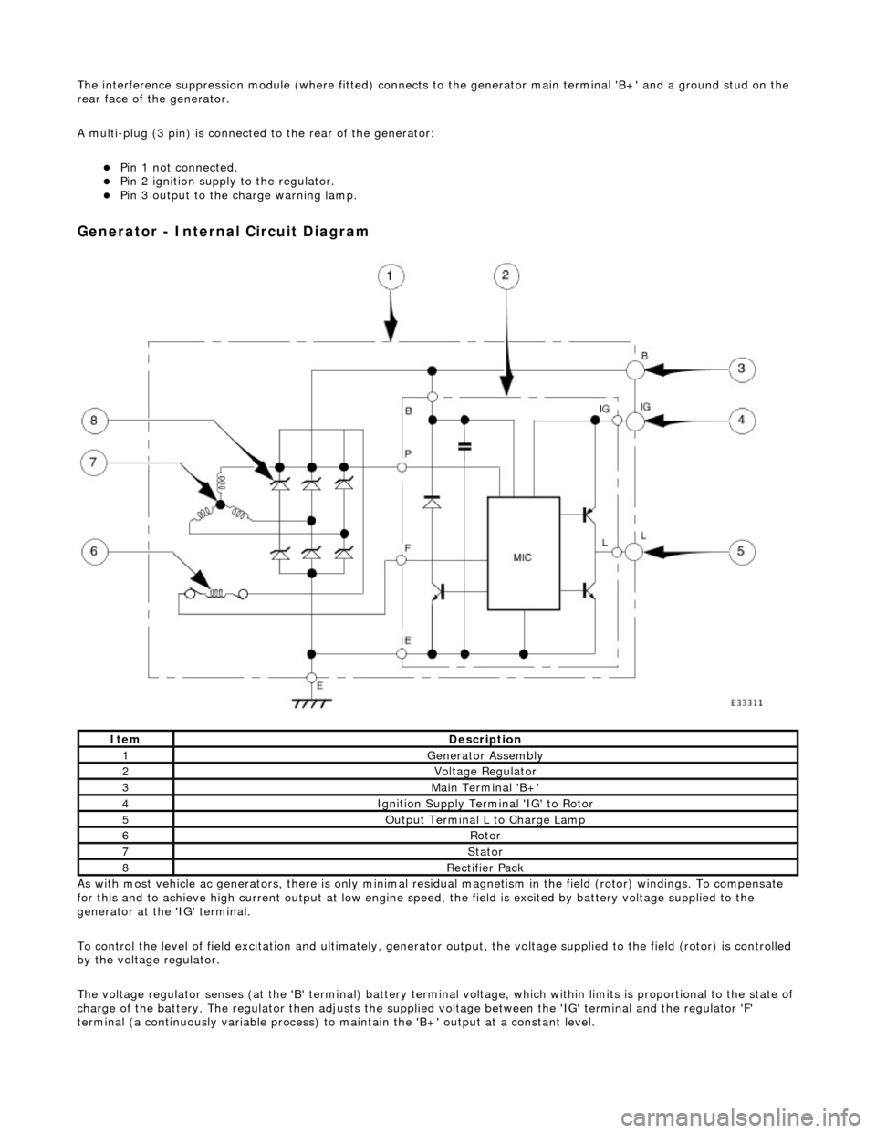
Generator - Internal Circuit Diagram
As with most vehicle ac generators, there is only minimal residual magnet ism in the field (rotor) windings. To compensate
for this and to achieve high current outp ut at low engine speed, the field is excited by battery voltage supplied to the
generator at the 'IG' terminal.
To control the level of field excitation and ultimately, generator output, the voltag e supplied to the field (rotor) is controlled
by the voltage regulator.
The voltage regulator senses (at the 'B' terminal) battery terminal voltage, which within limits is proportional to the state o f
charge of the battery. The regulator then adjusts the supplied voltage between the 'IG' terminal and the regulator 'F'
terminal (a continuously variable process) to maintain the 'B+' output at a constant level.
ItemDescription
1Generator Assembly
2Voltage Regulator
3Main Terminal 'B+'
4Ignition Supply Terminal 'IG' to Rotor
5Output Terminal L to Charge Lamp
6Rotor
7Stator
8Rectifier Pack