Page 2373 of 2490
5.
Turn steering wheel 90 degrees to left and partially tighten
module LH securing bolt.
6. Repeat steps 3 and 4 to fully ti ghten securing bolts and return
steering wheel to central position.
7. Fit ground cable to battery terminal. Refer to 86.15.15.
Page 2374 of 2490

Supplemental Restraint System - Passenger Air Bag Module
Removal and Installation
Removal
• WARNINGS:
FOLLOWING DISCONNECTION OF THE BATTERY, A PERIOD OF AT LEAST ONE MINUTE MUST BE ALLOWED TO ELAPSE
BEFORE ANY WORK IS CARRIED OUT ON AN AIR BAG MODULE.
FOLLOWING TEN YEARS IN SERVICE, AN AIR BAG MO DULE MUST BE REMOVED AND DISPOSED OF IN THE
APPROVED MANNER, AND A NEW AIR BAG MUST BE FITTED.
AIR BAGS CONTAIN A CHEMICAL IRRITANT. IF AN AIR BAG IS RENEWED, THE ORIGINAL UNIT MUST BE DISPOSED
OF IN ACCORDANCE WITH CURRENT SAFETY PROCEDURES.
IN THE EVENT OF A FAULT RUPTURING THE 10A BATTERY SUPPLY FUSE (F4 LOCATED IN THE FUSE-BOX AT THE
DRIVER'S END OF THE FASCIA), THE FUSE MUST NOT BE RENEWED UNTIL THE AIRBAG/SRS SYSTEM HAS BEEN DE-
ACTIVATED. FUSES OF ANY OTHER VALUE MUST NEVER BE USED, AS THIS CAN CAUSE DISARM FAILURE.
1. Remove battery cover and disc onnect ground cable from
terminal. Refer to 86.15.19.
2. Remove glove box. Refer to 76.52.03.
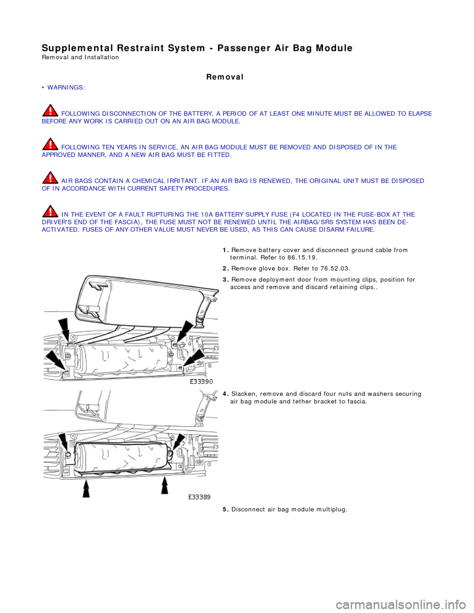
3. Remove deployment door from mounting clips, position for
access and remove and di scard retaining clips..
4. Slacken, remove and discard fo ur nuts and washers securing
air bag module and tether bracket to fascia.
5. Disconnect air bag module multiplug.
Page 2375 of 2490
Installation
• NOTE: The serial numbers of all supplementary restrain t system components must always be recorded against the VIN of
the vehicle.
6. Withdraw air bag module and remove from vehicle.
7. Slacken, remove and discard two bolts securing air bag tether
bracket to air bag module.
1. Position air bag module on teth er bracket and fit and tighten
two new securing bolts.
2. Position air bag module and deployment door mounting
bracket in fascia.
3. Fit and tighten four new nuts and washers securing air bag
Page 2376 of 2490
module and tether bracket to fascia.
4. Connect airbag module multiplug.
5. Fit air bag deployment d oor into mounting clips.
6. Fit glove box. Refer to Section 501-05.
7. Connect ground cable to battery terminal and fit battery cover.
Refer to 86.15.15.
Page 2377 of 2490

Supplemental Restraint System - Side Air Bag Module
Removal and Installation
Removal
• WARNINGS:
A SIDE AIR BAG MUST ONLY BE RENEWED IF A FAULT FLAG HAS OCCURRED. IN THE EVENT OF SIDE AIR BAG
DEPLOYMENT DUE TO SIDE IMPACT, THE COMPLETE SEAT MUST BE RENEWED.
FOLLOWING TEN YEARS IN SERVICE, AN AIR BAG MO DULE MUST BE REMOVED AND DISPOSED OF IN THE
APPROVED MANNER, AND A NEW AIR BAG MUST BE FITTED.
FOLLOWING DISCONNECTION OF THE BATTERY, A PERIOD OF AT LEAST FIFTEEN MINUTES MUST BE ALLOWED TO
ELAPSE BEFORE DISCONNECTING THE SINGLE-POINT SENSIN G (SPS) UNIT AND AN ELAPSE OF 2 MINUTES ALLOWED
BEFORE DISCONNECTING ANY OTHER SUPPLEMENTARY RESTRAINT SYSTEM COMPONENT.
AIR BAGS CONTAIN A CHEMICAL IRRITANT. IF AN AIR BAG IS RENEWED, THE DISCARDED UNIT MUST BE DISPOSED
OF IN ACCORDANCE WITH CURRENT SAFETY PROCEDURES.
IN THE EVENT OF A FAULT RUPTURING THE 10A BATTERY SUPPLY FUSE (F4 LOCATED IN THE FUSE-BOX AT THE
DRIVER'S END OF THE FASCIA), THE FUSE MUST NOT BE RENEWED UNTIL THE AIRBAG/SRS SYSTEM HAS BEEN DE-
ACTIVATED. FUSES OF ANY OTHER VALUE MUST NEVER BE USED, AS THIS CAN CAUSE DISARM FAILURE.
1. Remove battery cover and disc onnect ground cable from
battery terminal. Refer to 86.15.19.
2. Remove seat from vehi cle. Refer to 76.70.01.
3. Remove seat back fini sher. Refer to 76.70.09.
4. Partially remove squab cover and foam pad for access. Refer to
76.70.15
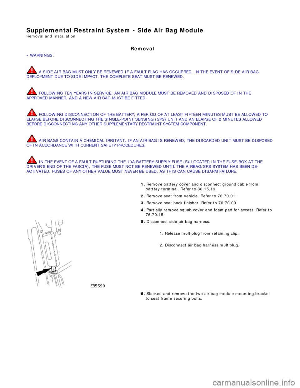
5. Disconnect side air bag harness.
1. Release multiplug from retaining clip.
2. Disconnect air ba g harness multiplug.
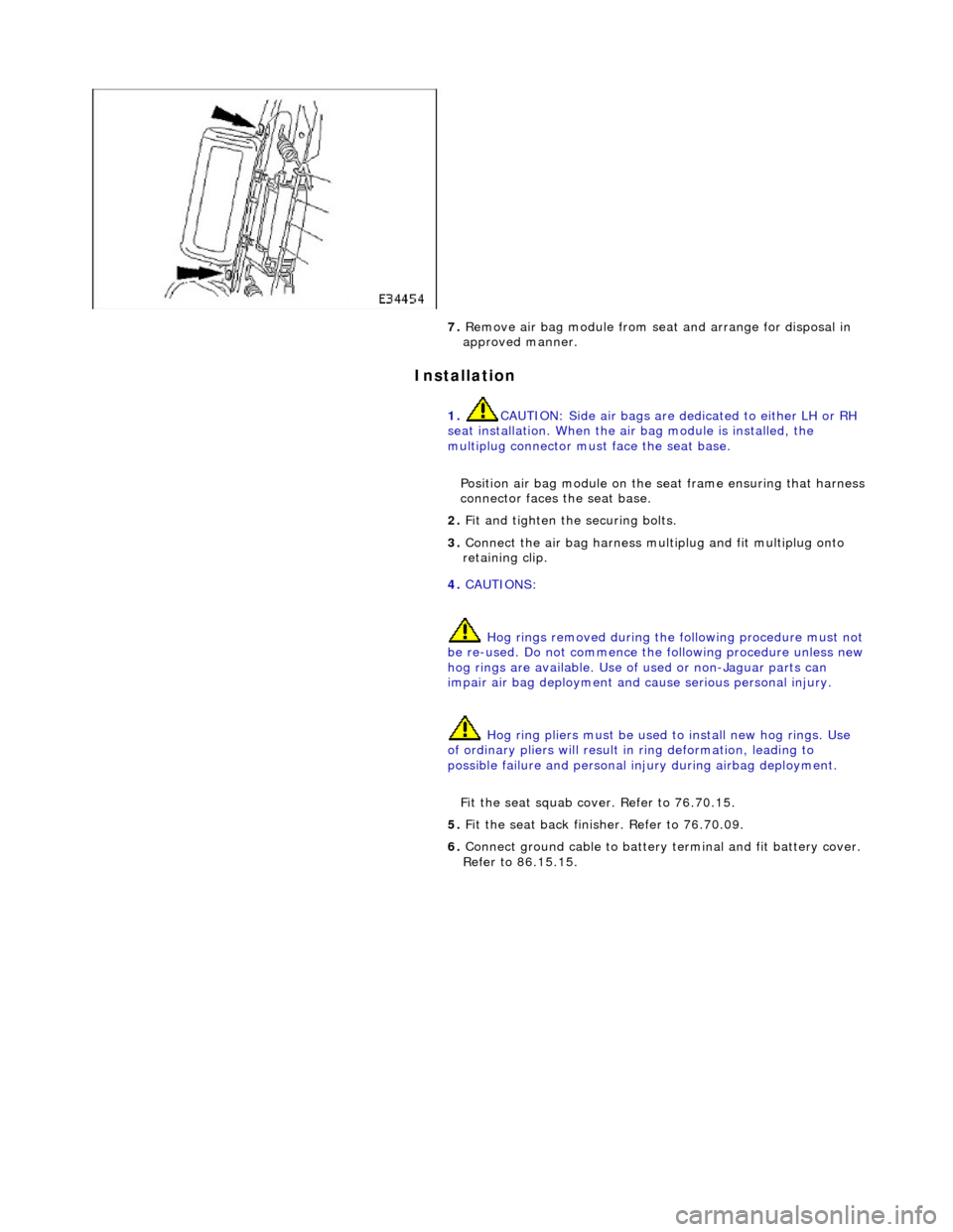
6. Slacken and remove the two air bag module mounting bracket
to seat frame securing bolts.
Page 2378 of 2490

Installation
7. Remove air bag module from seat and arrange for disposal in
approved manner.
1. CAUTION: Side air bags are de dicated to either LH or RH
seat installation. When the air bag module is installed, the
multiplug connector must face the seat base.
Position air bag module on the seat frame ensuring that harness
connector faces the seat base.
2. Fit and tighten the securing bolts.
3. Connect the air bag harness mult iplug and fit multiplug onto
retaining clip.
4. CAUTIONS:
Hog rings removed during the following procedure must not
be re-used. Do not commence the following procedure unless new hog rings are availabl e. Use of used or non-Jaguar parts can
impair air bag deployment and cause serious personal injury.
Hog ring pliers must be used to install new hog rings. Use
of ordinary pliers will result in ring deformation, leading to
possible failure and personal in jury during airbag deployment.
Fit the seat squab cover. Refer to 76.70.15.
5. Fit the seat back finisher. Refer to 76.70.09.
6. Connect ground cable to battery terminal and fit battery cover.
Refer to 86.15.15.
Page 2420 of 2490

lever mechanism driven by an electric motor. A sliding roof control module (SRCM) controls the motor in response to
selections made on the roof console switch , or input from the security system for automatic closing. Both the motor and the SRCM are accessed by removing the roof console.In the event of an electrical failure the sliding roof can be manually
operated. This is achieved by inserting a wide bladed screwdriver into a slot in the motor drive gear and turning clockwise to open or counter clockwise to close the sliding roof.
• NOTE: The drive gear becomes disengaged from the motor during manual operation. Before restoring electrical operation
the drive gear must be rotated one quarter turn in the reverse direction to re-engage the motor.
The SRCM is held in position by clips and has two electrical connectors in terfacing with the motor and the roof console
switch/security system. Prior to installing a new SRCM, the sun ro of must be in a neutral closed position. This provides the
SRCM with a sliding roof datum, to ensure accurate and consistent operation. Obstacle sensin g operates on closing in the
slide mode only. If the sliding roof lid encounters an ob struction between 4mm and 200mm from the closed position, the
SRCM detects increased motor load and reve rses the motor, driving the sliding roof to the fully open position. The sliding
roof lid surround seal has a metal inner sect ion which will deform on removal. If removed, this seal must be discarded and a
new seal must be installed on the lid using a Jaguar approved crimping tool.